MC10124 Quad TTL to MECL Translator - ON Semiconductor
MC10124 Quad TTL to MECL Translator - ON Semiconductor
MC10124 Quad TTL to MECL Translator - ON Semiconductor

You also want an ePaper? Increase the reach of your titles
YUMPU automatically turns print PDFs into web optimized ePapers that Google loves.
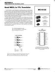
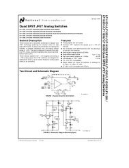
The <strong>MC10124</strong> is a quad transla<strong>to</strong>r for interfacing data and control<br />
signals between a saturated logic section and the <strong>MECL</strong> section of<br />
digital systems. The <strong>MC10124</strong> has <strong>TTL</strong> compatible inputs, and<br />
<strong>MECL</strong> complementary open–emitter outputs that allow use as an<br />
inverting/ non–inverting transla<strong>to</strong>r or as a differential line driver.<br />
When the common strobe input is at the low logic level, it forces all<br />
true outputs <strong>to</strong> a <strong>MECL</strong> low logic state and all inverting outputs <strong>to</strong> a<br />
<strong>MECL</strong> high logic state.<br />
Power supply requirements are ground, +5.0 Volts, and –5.2 Volts.<br />
Propagation delay of the <strong>MC10124</strong> is typically 3.5 ns. The dc levels<br />
are standard or Schottky <strong>TTL</strong> in, <strong>MECL</strong> 10,000 out.<br />
An advantage of this device is that <strong>TTL</strong> level information can be<br />
transmitted differentially, via balanced twisted pair lines, <strong>to</strong> the <strong>MECL</strong><br />
equipment, where the signal can be received by the MC10115 or<br />
MC10116 differential line receivers. The <strong>MC10124</strong> is useful in<br />
computers, instrumentation, peripheral controllers, test equipment,<br />
and digital communications systems.<br />
• P D = 380 mW typ/pkg (No Load)<br />
• t pd = 3.5 ns typ (+ 1.5 Vdc in <strong>to</strong> 50% out)<br />
• t r , t f = 2.5 ns typ (20%–80%)<br />
<br />
<br />
<br />
<br />
<br />
LOGIC DIAGRAM<br />
<br />
<br />
<br />
<br />
<br />
<br />
<br />
<br />
<br />
<br />
<br />
DIP PIN ASSIGNMENT<br />
http://onsemi.com<br />
CDIP–16<br />
L SUFFIX<br />
CASE 620<br />
PDIP–16<br />
P SUFFIX<br />
CASE 648<br />
PLCC–20<br />
FN SUFFIX<br />
CASE 775<br />
16<br />
A = Assembly Location<br />
WL = Wafer Lot<br />
YY = Year<br />
WW = Work Week<br />
ORDERING INFORMATI<strong>ON</strong><br />
MARKING<br />
DIAGRAMS<br />
Device Package Shipping<br />
<strong>MC10124</strong>L CDIP–16 25 Units / Rail<br />
<strong>MC10124</strong>P PDIP–16 25 Units / Rail<br />
<strong>MC10124</strong>FN PLCC–20 46 Units / Rail<br />
1<br />
16<br />
1<br />
<strong>MC10124</strong>L<br />
AWLYYWW<br />
<strong>MC10124</strong>P<br />
AWLYYWW<br />
1<br />
10124<br />
AWLYYWW<br />
<br />
<br />
<br />
<br />
<br />
<br />
<br />
<br />
<br />
<br />
<br />
<br />
<br />
<br />
<br />
<br />
<br />
<br />
<br />
<br />
<br />
<br />
<br />
<br />
<br />
<br />
<br />
<br />
<br />
<br />
<br />
<br />
<br />
Pin assignment is for Dual–in–Line Package.<br />
For PLCC pin assignment, see the Pin Conversion Tables on page 18<br />
of the <strong>ON</strong> Semiconduc<strong>to</strong>r <strong>MECL</strong> Data Book (DL122/D).<br />
© Semiconduc<strong>to</strong>r Components Industries, LLC, 2002<br />
January, 2002 – Rev. 7<br />
1 Publication Order Number:<br />
<strong>MC10124</strong>/D
<strong>MC10124</strong><br />
ELECTRICAL CHARACTERISTICS<br />
Characteristic<br />
Negative Power Supply<br />
Drain Current<br />
Symbol<br />
Test Limits<br />
Pin<br />
Under<br />
–30°C +25°C +85°C<br />
Test Min Max Min Typ Max Min Max Unit<br />
I E 8 72 66 72 mAdc<br />
Positive Power Supply I CCH 9 16 16 18 mAdc<br />
Drain Current<br />
I CCL 9 25 25 25 mAdc<br />
Reverse Current I R 6<br />
7<br />
Forward Current I F 6<br />
7<br />
Input Breakdown Voltage BV in 6<br />
7<br />
Clamp Input Voltage V I 6<br />
7<br />
High Output Voltage V OH 1<br />
3<br />
Low Output Voltage V OL 1<br />
3<br />
High Threshold Voltage V OHA 1<br />
3<br />
Low Threshold Voltage V OLA 1<br />
3<br />
Switching Times (50Ω<br />
Load)<br />
Propagation Delay<br />
(+3.5Vdc <strong>to</strong> 50%) 1 t 6+1+<br />
t 6–1–<br />
t 7+1+<br />
t 7–1–<br />
t 7+3–<br />
t 7–3+<br />
1<br />
1<br />
1<br />
1<br />
3<br />
3<br />
5.5<br />
5.5<br />
–1.060<br />
–1.060<br />
–1.890<br />
–1.890<br />
–1.080<br />
–1.080<br />
1.5<br />
1.0<br />
1.5<br />
1.0<br />
1.5<br />
1.0<br />
200<br />
50<br />
–12.8<br />
–3.2<br />
–1.5<br />
–1.5<br />
–0.890<br />
–0.890<br />
–1.675<br />
–1.675<br />
–1.655<br />
–1.655<br />
6.8<br />
6.0<br />
6.8<br />
6.0<br />
6.8<br />
6.0<br />
5.5<br />
5.5<br />
–0.960<br />
–0.960<br />
–1.850<br />
–1.850<br />
–0.980<br />
–0.980<br />
1.0<br />
1.0<br />
1.0<br />
1.0<br />
1.0<br />
1.0<br />
3.5<br />
3.5<br />
3.5<br />
3.5<br />
3.5<br />
3.5<br />
200<br />
50<br />
–12.8<br />
–3.2<br />
–1.5<br />
–1.5<br />
–0.810<br />
–0.810<br />
–1.650<br />
–1.650<br />
–1.630<br />
–1.630<br />
6.0<br />
6.0<br />
6.0<br />
6.0<br />
6.0<br />
6.0<br />
5.5<br />
5.5<br />
–0.890<br />
–0.890<br />
–1.825<br />
–1.825<br />
–0.910<br />
–0.910<br />
1.0<br />
1.5<br />
1.0<br />
1.5<br />
1.0<br />
1.5<br />
200<br />
50<br />
–12.8<br />
–3.2<br />
–1.5<br />
–1.5<br />
–0.700<br />
–0.700<br />
–1.615<br />
–1.615<br />
–1.595<br />
–1.595<br />
6.0<br />
6.8<br />
6.0<br />
6.8<br />
6.0<br />
6.8<br />
µAdc<br />
mAdc<br />
Vdc<br />
Vdc<br />
Vdc<br />
Vdc<br />
Vdc<br />
Vdc<br />
ns<br />
Rise Time (20 <strong>to</strong> 80%) t 1+ 1 1.0 4.2 1.1 2.5 3.9 1.1 4.3<br />
Fall Time (20 <strong>to</strong> 80%) t 1– 1 1.0 4.2 1.1 2.5 3.9 1.1 4.3<br />
1. See switching time test circuit. Propagation delay for this circuit is specified from +1.5Vdc in <strong>to</strong> the 50% point on the output waveform. The<br />
+3.5Vdc is shown here because all logic and supply levels are shifted 2 volts positive.<br />
http://onsemi.com<br />
2
<strong>MC10124</strong><br />
ELECTRICAL CHARACTERISTICS (continued)<br />
TEST VOLTAGE VALUES (Volts)<br />
Characteristic<br />
Negative Power Supply Drain<br />
Current<br />
@ Test Temperature V IH V ILmax V IHA’ V ILA’ V F<br />
–30°C +4.0 +0.40 +2.00 +1.10 +0.40<br />
+25°C +4.0 +0.40 +1.80 +1.10 +0.40<br />
+85°C +4.0 +0.40 +1.80 +0.90 +0.40<br />
Pin<br />
Under<br />
TEST VOLTAGE APPLIED TO PINS LISTED BELOW<br />
Symbol Test V IH V ILmax V IHA’ V ILA’ V F Gnd<br />
I E 8 16<br />
Positive Power Supply Drain I CCH 9 5,6,7,10,11 16<br />
Current<br />
I CCL 9 5,6,7,10,11,16<br />
Reverse Current I R 6<br />
7<br />
Forward Current I F 6<br />
7<br />
Input Breakdown Voltage BV in 6<br />
7<br />
Clamp Input Voltage V I 6<br />
7<br />
High Output Voltage V OH 1<br />
3<br />
5,7,10,11<br />
6<br />
Low Output Voltage V OL 1<br />
3 6,7<br />
High Threshold Voltage V OHA 1<br />
3<br />
Low Threshold Voltage V OLA 1<br />
3<br />
6,7<br />
6<br />
6<br />
6,7<br />
5,7,10,11<br />
6<br />
6<br />
7<br />
16<br />
16<br />
16<br />
16<br />
5,7,10,11,16<br />
6,16<br />
16<br />
16<br />
16<br />
16<br />
6,7 16<br />
16<br />
6<br />
6 7<br />
7<br />
7<br />
16<br />
16<br />
7 16<br />
16<br />
Switching Times (50Ω Load) +6.0 V Pulse In Pulse Out +2.0 V<br />
Propagation Delay<br />
(+3.5Vdc <strong>to</strong> 50%) 1 t 6+1+<br />
t 6–1–<br />
t 7+1+<br />
t 7–1–<br />
t 7+3–<br />
t 7–3+<br />
1<br />
1<br />
1<br />
1<br />
3<br />
3<br />
7<br />
7<br />
6<br />
6<br />
6<br />
6<br />
Rise Time (20 <strong>to</strong> 80%) t 1+ 1 6 7 1 16<br />
Fall Time (20 <strong>to</strong> 80%) t 1– 1 6 7 1 16<br />
1. See switching time test circuit. Propagation delay for this circuit is specified from +1.5Vdc in <strong>to</strong> the 50% point on the output waveform. The<br />
+3.5Vdc is shown here because all logic and supply levels are shifted 2 volts positive.<br />
6<br />
6<br />
7<br />
7<br />
7<br />
7<br />
1<br />
1<br />
1<br />
1<br />
3<br />
3<br />
16<br />
16<br />
16<br />
16<br />
16<br />
16<br />
http://onsemi.com<br />
3
<strong>MC10124</strong><br />
ELECTRICAL CHARACTERISTICS (continued)<br />
TEST VOLTAGE VALUES (Volts)<br />
(mA)<br />
Characteristic<br />
Negative Power Supply Drain<br />
Current<br />
@ Test Temperature V R V CC V EE I I I in<br />
–30°C +2.40 +5.00 –5.2 –10 +1.0<br />
+25°C +2.40 +5.00 –5.2 –10 +1.0<br />
+85°C +2.40 +5.00 –5.2 –10 +1.0<br />
Pin<br />
Under<br />
TEST VOLTAGE APPLIED TO PINS LISTED BELOW<br />
Symbol Test V R V CC V EE I I I in Gnd<br />
I E 8 9 8 16<br />
Positive Power Supply Drain I CCH 9 9 8 16<br />
Current<br />
I CCL 9 9 8 5,6,7,10,11,16<br />
Reverse Current I R 6<br />
7<br />
Forward Current I F 6<br />
7<br />
Input Breakdown Voltage BV in 6<br />
7<br />
Clamp Input Voltage V I 6<br />
7<br />
High Output Voltage V OH 1<br />
3<br />
Low Output Voltage V OL 1<br />
3<br />
High Threshold Voltage V OHA 1<br />
3<br />
Low Threshold Voltage V OLA 1<br />
3<br />
6<br />
7<br />
9<br />
9<br />
9<br />
9<br />
9<br />
9<br />
9<br />
9<br />
9<br />
9<br />
9<br />
9<br />
9<br />
9<br />
8<br />
8<br />
8<br />
8<br />
8<br />
8<br />
8<br />
8<br />
8<br />
8<br />
8<br />
8<br />
8<br />
8<br />
6<br />
7<br />
6<br />
7<br />
16<br />
16<br />
16<br />
16<br />
5,7,10,11,16<br />
6,16<br />
Switching Times (50Ω Load) +7.0 V –3.2 V +2.0 V<br />
Propagation Delay<br />
(+3.5Vdc <strong>to</strong> 50%) 1 t 6+1+<br />
t 6–1–<br />
t 7+1+<br />
t 7–1–<br />
t 7+3–<br />
t 7–3+<br />
1<br />
1<br />
1<br />
1<br />
3<br />
3<br />
Rise Time (20 <strong>to</strong> 80%) t 1+ 1 9 8 16<br />
Fall Time (20 <strong>to</strong> 80%) t 1– 1 9 8 16<br />
1. See switching time test circuit. Propagation delay for this circuit is specified from +1.5Vdc in <strong>to</strong> the 50% point on the output waveform. The<br />
+3.5Vdc is shown here because all logic and supply levels are shifted 2 volts positive.<br />
Each <strong>MECL</strong> 10,000 series circuit has been designed <strong>to</strong> meet the dc specifications shown in the test table, after thermal equilibrium has been<br />
established. The circuit is in a test socket or mounted on a printed circuit board and transverse air flow greater than 500 linear fpm is maintained.<br />
Outputs are terminated through a 50–ohm resis<strong>to</strong>r <strong>to</strong> –2.0 volts. Test procedures are shown for only one gate. The other gates are tested in the<br />
same manner.<br />
9<br />
9<br />
9<br />
9<br />
9<br />
9<br />
9<br />
9<br />
8<br />
8<br />
8<br />
8<br />
8<br />
8<br />
8<br />
8<br />
16<br />
16<br />
16<br />
16<br />
16<br />
16<br />
16<br />
16<br />
16<br />
16<br />
16<br />
16<br />
16<br />
16<br />
16<br />
16<br />
http://onsemi.com<br />
4
<strong>MC10124</strong><br />
SWITCHING TIME TEST CIRCUIT<br />
<br />
<br />
<br />
<br />
<br />
<br />
<br />
<br />
<br />
µ µ<br />
µ <br />
<br />
<br />
<br />
±<br />
<br />
<br />
<br />
<br />
<br />
<br />
<br />
<br />
<br />
<br />
<br />
<br />
<br />
<br />
<br />
<br />
<br />
<br />
µ µ µ<br />
<br />
<br />
<br />
<br />
<br />
<br />
<br />
<br />
<br />
<br />
NOTE: All power supply and logic levels are shown<br />
shifted 2 volts positive.<br />
http://onsemi.com<br />
5
<strong>MC10124</strong><br />
PACKAGE DIMENSI<strong>ON</strong>S<br />
PLCC–20<br />
FN SUFFIX<br />
PLASTIC PLCC PACKAGE<br />
CASE 775–02<br />
ISSUE C<br />
B<br />
<br />
<br />
<br />
<br />
<br />
–N–<br />
Y BRK<br />
U<br />
<br />
<br />
<br />
<br />
<br />
D<br />
–L–<br />
–M–<br />
Z<br />
W<br />
<br />
<br />
D<br />
X<br />
G1<br />
<br />
<br />
<br />
<br />
<br />
V<br />
VIEW D–D<br />
Z<br />
A<br />
R<br />
<br />
<br />
<br />
<br />
<br />
<br />
<br />
<br />
<br />
<br />
K1<br />
H<br />
<br />
<br />
<br />
<br />
<br />
C<br />
<br />
G<br />
G1<br />
<br />
<br />
<br />
E<br />
<br />
J –T– <br />
<br />
VIEW S<br />
<br />
VIEW S<br />
<br />
<br />
<br />
<br />
<br />
<br />
<br />
<br />
<br />
<br />
<br />
<br />
<br />
<br />
<br />
<br />
<br />
<br />
<br />
<br />
<br />
<br />
<br />
<br />
<br />
<br />
<br />
K<br />
F<br />
<br />
<br />
<br />
<br />
<br />
<br />
<br />
<br />
<br />
<br />
<br />
<br />
<br />
<br />
<br />
<br />
<br />
<br />
<br />
<br />
<br />
<br />
<br />
http://onsemi.com<br />
6
<strong>MC10124</strong><br />
PACKAGE DIMENSI<strong>ON</strong>S<br />
–T–<br />
<br />
<br />
F<br />
<br />
<br />
–A–<br />
<br />
<br />
E<br />
G<br />
D 16 PL<br />
<br />
–B–<br />
C<br />
N<br />
<br />
CDIP–16<br />
L SUFFIX<br />
CERAMIC DIP PACKAGE<br />
CASE 620–10<br />
ISSUE T<br />
K<br />
L<br />
M<br />
J 16 PL<br />
<br />
<br />
<br />
<br />
<br />
<br />
<br />
<br />
<br />
<br />
<br />
<br />
<br />
<br />
<br />
<br />
<br />
<br />
<br />
<br />
<br />
<br />
<br />
<br />
<br />
<br />
<br />
<br />
<br />
H<br />
–A–<br />
G<br />
<br />
B<br />
<br />
F<br />
C<br />
S<br />
K<br />
D 16 PL<br />
<br />
<br />
–T– <br />
<br />
<br />
<br />
PDIP–16<br />
P SUFFIX<br />
PLASTIC DIP PACKAGE<br />
CASE 648–08<br />
ISSUE R<br />
J<br />
L<br />
M<br />
<br />
<br />
<br />
<br />
<br />
<br />
<br />
<br />
<br />
<br />
<br />
<br />
<br />
<br />
<br />
<br />
<br />
<br />
<br />
<br />
<br />
<br />
<br />
<br />
<br />
http://onsemi.com<br />
7
<strong>MC10124</strong><br />
<strong>ON</strong> Semiconduc<strong>to</strong>r and are trademarks of Semiconduc<strong>to</strong>r Components Industries, LLC (SCILLC). SCILLC reserves the right <strong>to</strong> make changes<br />
without further notice <strong>to</strong> any products herein. SCILLC makes no warranty, representation or guarantee regarding the suitability of its products for any particular<br />
purpose, nor does SCILLC assume any liability arising out of the application or use of any product or circuit, and specifically disclaims any and all liability,<br />
including without limitation special, consequential or incidental damages. “Typical” parameters which may be provided in SCILLC data sheets and/or<br />
specifications can and do vary in different applications and actual performance may vary over time. All operating parameters, including “Typicals” must be<br />
validated for each cus<strong>to</strong>mer application by cus<strong>to</strong>mer’s technical experts. SCILLC does not convey any license under its patent rights nor the rights of others.<br />
SCILLC products are not designed, intended, or authorized for use as components in systems intended for surgical implant in<strong>to</strong> the body, or other applications<br />
intended <strong>to</strong> support or sustain life, or for any other application in which the failure of the SCILLC product could create a situation where personal injury or<br />
death may occur. Should Buyer purchase or use SCILLC products for any such unintended or unauthorized application, Buyer shall indemnify and hold<br />
SCILLC and its officers, employees, subsidiaries, affiliates, and distribu<strong>to</strong>rs harmless against all claims, costs, damages, and expenses, and reasonable<br />
at<strong>to</strong>rney fees arising out of, directly or indirectly, any claim of personal injury or death associated with such unintended or unauthorized use, even if such claim<br />
alleges that SCILLC was negligent regarding the design or manufacture of the part. SCILLC is an Equal Opportunity/Affirmative Action Employer.<br />
PUBLICATI<strong>ON</strong> ORDERING INFORMATI<strong>ON</strong><br />
Literature Fulfillment:<br />
Literature Distribution Center for <strong>ON</strong> Semiconduc<strong>to</strong>r<br />
P.O. Box 5163, Denver, Colorado 80217 USA<br />
Phone: 303–675–2175 or 800–344–3860 Toll Free USA/Canada<br />
Fax: 303–675–2176 or 800–344–3867 Toll Free USA/Canada<br />
Email: <strong>ON</strong>lit@hibbertco.com<br />
N. American Technical Support: 800–282–9855 Toll Free USA/Canada<br />
JAPAN: <strong>ON</strong> Semiconduc<strong>to</strong>r, Japan Cus<strong>to</strong>mer Focus Center<br />
4–32–1 Nishi–Gotanda, Shinagawa–ku, Tokyo, Japan 141–0031<br />
Phone: 81–3–5740–2700<br />
Email: r14525@onsemi.com<br />
<strong>ON</strong> Semiconduc<strong>to</strong>r Website: http://onsemi.com<br />
For additional information, please contact your local<br />
Sales Representative.<br />
http://onsemi.com<br />
8<br />
<strong>MC10124</strong>/D