HYDRA 830(M) - til india
HYDRA 830(M) - til india
HYDRA 830(M) - til india

You also want an ePaper? Increase the reach of your titles
YUMPU automatically turns print PDFs into web optimized ePapers that Google loves.
150 LPI<br />
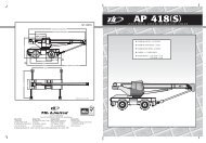
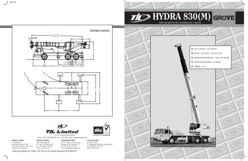
<strong>HYDRA</strong> <strong>830</strong>(M)<br />
0.28m<br />
9.4m RET<br />
22.3m EXT.<br />
2.13m 1.4m<br />
3.25m<br />
<br />
<br />
<br />
0.23m<br />
0.76m<br />
0.76m<br />
2.34m 2.06m<br />
2.00m 5.18m<br />
2.07m<br />
<br />
<br />
11.5m<br />
7.75m<br />
3.00m<br />
6.95m<br />
2.43m<br />
2.50m<br />
5.50m<br />
6.00m<br />
3.04m<br />
4.4m<br />
517, B.T. Road, Kolkata 700 058<br />
Phone : 2553 1352/1393/1882 , Fax : 2553 2546 E-Mail : mktkmt@<strong>til</strong><strong>india</strong>.com<br />
Kolkata Office Mumbai Office Sahibabad Office Chennai Office<br />
1, Taratolla Road D105, Thane Belapur Rd. Plot No. 11, Site No. 4 Industrial Area Jhaver Plaza, 7th floor<br />
EN 29001/ISO 9001/BS 5750<br />
APPROVED BY BVQI<br />
Garden Reach, Kolkata-700 024 P.O. Nerul, Navi Mubai 400 076 Sahibabad 201 010, Ghaziabad, U.P. 1-A, Nungambakkam High Road, Chennai 600 034<br />
Fax : 2469-2143/3731 Ph : 2469-3732-36 Fax : 2768 7203 Ph : 2763 1908 Fax : 2770 365 Ph : 2777 0945 Fax : 2827 9681 Ph : 2827 0723<br />
E-Mail : mhg-er@<strong>til</strong><strong>india</strong>.com E-Mail : <strong>til</strong>_bby@vsnl.net E-Mail : shb-mhgmktg@<strong>til</strong><strong>india</strong>.com E-Mail : <strong>til</strong>chn@vsnl.net<br />
Technical Specification TIL / <strong>830</strong>(M) / 0699. This cancels Technical Specification TIL/<strong>830</strong>(M)/0796<br />
NATIONAL<br />
ACCREDITATION<br />
OF CERTIFICATION<br />
BODIES
150 LPI<br />
SUPERSTRUCTURE SPECIFICATION<br />
CARRIER SPECIFICATION<br />
Superstructure<br />
Frame<br />
Boom Derricking<br />
System<br />
Boom Angle Maximum 78°.<br />
Derricking Speed<br />
Slew System<br />
Slew Speed<br />
Hoist System<br />
Line Speed<br />
Max. Line Pull<br />
Maximum Capacity<br />
Hookblock<br />
Operator’s Cab<br />
Fabricated from high tensile steel plates and<br />
sections.<br />
One double acting hydraulic cylinder with integral holding<br />
valve.<br />
Maximum to minimum radius in 60 secs.<br />
Ball bearing swing circle with 360° continuous rotation.<br />
Planetary gearbox with foot applied multi-disc wet brake.<br />
Spring applied hydraulically released swing brake and<br />
mechanical house lock operated from cab.<br />
Maximum 2.0 RPM. (Unladen)<br />
Power up and down, equal speed, planetary reduction with<br />
automatic spring applied multi-disc brake and hoist drum<br />
cable followers. 16 mm (5/8 in) dia non-rotating wire rope.<br />
Top layer 110m/min. (Unladen)<br />
4100 kgs.<br />
30 tonnes; 4 sheaves.<br />
Totally enclosed steel construction, full vision type. Control<br />
levers for all craning functions. All windows fitted with<br />
toughened safety glass. Lockable sliding door, cab interior<br />
light, pantograph type electric wiper. Electric horn,<br />
circulating air fan.<br />
Boom<br />
Boom Nose<br />
Telescoping<br />
System<br />
Telescoping<br />
Speed<br />
OPTIONALS<br />
Fixed Swingaway<br />
Extension<br />
9.4m – 22.3m three section trapezoidal full power boom.<br />
Telescoping is sequenced-synchronized with single lever<br />
control. Telescopic sections slide on adjustable and<br />
replaceable low friction wear pads.<br />
Four steel sheaves mounted on heavy duty tapered roller<br />
bearings with removable pin-type rope guards. Quick reeve<br />
type boom nose.<br />
Two sequence telescope cylinders fitted with cartridge type<br />
holding valve to sustain telescoping ram in the event of hyd.<br />
failure and provide positively controlled boom retraction.<br />
7.2m/min. (Unladen).<br />
7.6M fixed length non-offsettable lattice swingaway boom<br />
extension.<br />
Fixed Offsettable 7.6M lattice swingaway boom extension with integral offset<br />
Swingaway mechanism, offsettable at 0° or 30°.<br />
Extension<br />
Telescopic<br />
7.6M to 13.1M telescopic lattice swingaway extension<br />
Swingaway with integral offset mechanism, offsettable at 0° or 30°.<br />
Extension<br />
Auxiliary<br />
Boom Nose<br />
Removable auxiliary boom nose with removable pin type<br />
rope guard.<br />
Carrier<br />
Outriggers<br />
<strong>HYDRA</strong>ULIC SYSTEM<br />
Valves<br />
Pump<br />
Filter<br />
Reservoir<br />
Engine<br />
Clutch<br />
6x4 wheel right hand drive purpose built heavy duty frame<br />
of torsion box construction with integral outrigger housing<br />
and fabricated from high strength steel plates and sections.<br />
Hydraulically operated outrigger system, comprising four<br />
independently controlled hydraulic telescopic horizontal<br />
beams with vertical hydraulic jacks for over side and over<br />
rear operation. Plus one vertical hydraulic jack mounted<br />
under front of carrier to permit full 360 deg lifting duties. All<br />
vertical jacks are fitted with positive lock valves. Easy-fit<br />
outrigger feet are provided with stowage facility on carrier.<br />
Hydraulic over-load valves automatically protect pumps and<br />
crane structure from excessive pressure.<br />
Triple gear pumps driven from power-take-off mounted on<br />
gear box.<br />
Return line type, full flow with bypass protection and<br />
service indicator. Replaceable cartridge.<br />
Capacity 390 litres with spin-on breather filter, external<br />
sight, oil temperature gauge, clean out excess, strap<br />
mounted to frame.<br />
Heavy duty, water cooled, diesel engine of adequate horse<br />
power.<br />
Single dry plate hydraulically operated servo assisted.<br />
Steering<br />
BRAKES<br />
Service<br />
Parking &<br />
Emergency<br />
Wheels & Tyres<br />
Operator’s Cab<br />
Instrumentation<br />
Electrical Equipment<br />
Tool Box<br />
Hydraulic power assisted steering to front steering axle.<br />
Air operated on all wheels by means of foot operated pedal<br />
in operator’s cab.<br />
By means of air operated spring actuator through control<br />
valve in operator’s cab on rear bogie, fail safe.<br />
Pneumatic 11.00x20x16 PR tyres, singles front and twins<br />
rear. Spare wheel rim provided.<br />
Steel construction full width cab with electric fan, cab with<br />
interior light, opening windows fitted with toughened glass.<br />
Two lockable doors, electric windscreen wiper to front of<br />
windscreen. Upholstered and adjustable operator’s seat.<br />
Automotive controls include steering wheel, pedals for<br />
clutch, brake and accelerator.<br />
Air pressure gauge, engine oil pressure gauge, ammeter,<br />
water temperature gauge, speedometer, warning light for<br />
alternator.<br />
24 volt starting and lighting system includes two combined<br />
dipping head lamps, side, rear and stop lamp. Flashing<br />
direction indicators.<br />
Tool Kit for normal maintenance.<br />
Load Moment<br />
& Anti-Two<br />
Block System<br />
Standard load moment and anti-two block system with<br />
audio-visual warning and control lever lockout. These<br />
systems provide electronic display of boom angle, length,<br />
radius, relative load moment, maximum permissible load<br />
and load indication and warning of impending two-block<br />
conditions.<br />
Auxiliary<br />
Hoist<br />
Gear Box<br />
Fuel Tank<br />
Constantmesh, five forward and one reverse, obtained via a<br />
single lever control. Plus four forward and one reverse with<br />
crawler arrangement.<br />
Capacity 165 litres.<br />
Counterweight<br />
Integral with superstructure.<br />
<strong>HYDRA</strong>ULIC SYSTEM<br />
Valves Precision four way double acting control valves. 3<br />
individual valve banks permits simultaneous control of<br />
multiple crane functions.<br />
Oil Cooler<br />
Pressure<br />
Check Panel<br />
Remote mounted with thermostatically controlled electric<br />
motor driven fan.<br />
System pressure test panel with quick release type fitting for<br />
each circuit.<br />
AXLES<br />
Front Axle<br />
Rear Bogie<br />
Steering axle mounted on semi-elliptical leaf spring.<br />
Heavy duty, fully floating type with hub reduction mounted<br />
on specially designed rocker beam to allow maximum<br />
articulation on uneven ground. Air operated interaxle<br />
differential lock.<br />
Axle Loading Front Axle – 6.7 tonnes<br />
Rear Bogie – 10.2 + 10.2 tonnes<br />
Technical Specification TIL / <strong>830</strong>(M) / 0699. Technical Specification TIL / <strong>830</strong>(M) / 0699.
150 LPI<br />
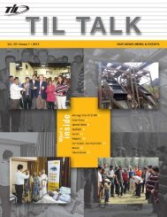
LIFTING CAPACITIES<br />
HEIGHT OF LIFT — 9.4M – 22.3M FULL POWER BOOM<br />
85% RATING<br />
MAIN BOOM CAPACITIES IN TONNES WITH OUTRIGGERS FULLY EXTENDED<br />
THROUGH FULL 360° SLEW<br />
Radius<br />
in<br />
Meters<br />
Boom Length in Meters<br />
9.4 12.2 15.2 15.9 18.3 21.3 22.3<br />
3 30.0 27.0 22.5 18.5<br />
3.5 27.5 26.0 21.0 17.0 14.0<br />
Lifting Capacities on Rubber<br />
Radius<br />
in<br />
Meters<br />
9.4m Boom<br />
11.00 x 20 x 16PR Tyre<br />
up to 2 km/hr<br />
Over Rear only<br />
3.00 6.50<br />
58<br />
56<br />
54<br />
52<br />
WORKING RANGE DIAGRAM<br />
(BOOM DEFLECTION NOT SHOWN)<br />
4 24.5 24.4 20.5 16.0 13.1<br />
3.50 6.00<br />
50<br />
4.5 21.9 21.65 19.5 15.5 12.5 12.0<br />
4.00 5.85<br />
48<br />
5 19.65 19.4 18.35 15.0 12.0 11.0<br />
4.50 4.90<br />
46<br />
6 15.75 15.50 15.0 14.0 11.00 10.0 9.5<br />
7 11.80 11.75 11.6 11.55 10.00 8.3 8.25<br />
8 9.12 9.02 9.0 9.0 7.3 7.0<br />
9 7.25 7.2 7.15 7.5 6.5 6.0<br />
10 5.80 5.85 5.85 6.15 5.7 5.0<br />
12 3.95 3.95 4.25 4.5 4.0<br />
14 3.0 3.3 3.0<br />
16 2.1 2.4 2.2<br />
18 1.70 1.5<br />
20 1.0<br />
5.00 3.95<br />
6.00 2.30<br />
7.00 1.35<br />
ELEVATION IN METERS<br />
44<br />
42<br />
40<br />
38<br />
36<br />
34<br />
32<br />
30<br />
28<br />
26<br />
24<br />
22<br />
20<br />
18<br />
40°<br />
50°<br />
60°<br />
70°<br />
22.3<br />
21.3<br />
18.3<br />
15.9<br />
15.2<br />
16<br />
14<br />
30°<br />
12.2<br />
Important Notes<br />
WARNING : THIS CHART IS ONLY A GUIDE. The Notes below are for illustration only and should not be relied upon to operate<br />
the crane. The individual crane’s load chart, operating instructions and other instruction plates must be read and understood<br />
prior to operating the crane.<br />
1. All rated loads have been tested to and meet minimum requirements of IS 4573-1982 – Specification for Power Driven Mobile Cranes,<br />
and do not exceed 85% of the tipping load on outriggers as determined by SAE J765 OCT80 Crane Stability Test Code.<br />
2. The weight of hookblock, slings and all similarly used load handling devices must be added to the weight of the load.<br />
3. Capacities appearing above the bold line are based on structural strength and tipping should not be relied upon as a capacity limitation.<br />
4. All capacities are for crane on firm, level surface. It must be necessary to have structural supports under the outrigger floats or tires to<br />
spread the load to a larger bearing surface.<br />
5. When either boom length or radius or both are between values listed, the smallest load shown at either the next larger radius or boom<br />
length shall be used.<br />
6. For outrigger operation, all outriggers shall be fully extended with tires raised free of ground before raising the boom or lifting device.<br />
Technical Specification TIL / <strong>830</strong>(M) / 0699.<br />
12<br />
10<br />
8<br />
6<br />
4<br />
2<br />
0<br />
44<br />
42 40 38 36 34<br />
Technical Specification TIL / <strong>830</strong>(M) / 0699.<br />
10°<br />
0°<br />
-3°<br />
20°<br />
32 30 28 26 24 22 20 18 16 14 12 10 8 6 4<br />
OPERATING RADIUS IN METERS FROM AXIS OF ROTATION<br />
NOTE : LIMITS SHOWN ARE FOR OUTRIGGERS FULLY EXTENDED – 360° ONLY<br />
9.4<br />
78° MAX.<br />
BOOM ANGLE<br />
AXIS OF ROTATION
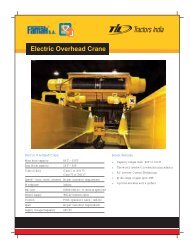
150 LPI<br />
METRIC 85% LIFTING CAPACITIES (TONNES)<br />
ON OUTRIGGERS FULLY EXTENDED<br />
HEIGHT OF LIFT — 9.4M – 22.3M FULL POWER BOOM<br />
7.6M–13.1M TELE SWINGAWAY – 360°<br />
7.6M SWINGAWAY – 360° – NON-OFFSET TYPE<br />
Radius<br />
in<br />
Meters<br />
7.6m Length 13.1m Length<br />
0° Offset 30° Offset 0° Offset 30° Offset<br />
Radius<br />
in<br />
Meters<br />
Boom Length<br />
29.9m<br />
WORKING RANGE DIAGRAM<br />
(BOOM DEFLECTION NOT SHOWN)<br />
7.00 5.75<br />
7.00 6.00<br />
58<br />
8.00 5.25 3.00<br />
8.00 5.45<br />
56<br />
9.00 4.75 2.90 2.90<br />
9.00 5.00<br />
54<br />
52<br />
10.00 4.25 2.80 2.80<br />
10.00 4.50<br />
50<br />
12.00 3.45 2.70 2.60 1.95<br />
12.00 3.65<br />
48<br />
14.00 2.85 2.50 2.40 1.85<br />
14.00 3.00<br />
46<br />
44<br />
16.00 2.40 2.15 2.20 1.75<br />
18.00 1.90 1.80 1.90 1.65<br />
20.00 1.35 1.40 1.70 1.50<br />
22.00 0.95 1.00 1.30 1.35<br />
24.00 0.60 1.00 1.15<br />
26.00 0.75 0.90<br />
28.00 0.50<br />
7.6M SWINGAWAY – 360° – OFFSET TYPE<br />
Radius<br />
in<br />
Meters<br />
7.6m Length<br />
0° Offset 30° Offset<br />
Important Notes<br />
16.00 2.55<br />
18.00 2.20<br />
20.00 1.75<br />
22.00 1.35<br />
24.00 1.00<br />
WARNING : THIS CHART IS ONLY A GUIDE. The Notes<br />
below are for illustration only and should not be relied<br />
upon to operate the crane. The individual crane’s load<br />
chart, operating instructions and other instruction<br />
plates must be read and understood prior to operating<br />
the crane.<br />
ELEVATION IN METERS<br />
42<br />
40<br />
38<br />
36<br />
34<br />
32<br />
30<br />
28<br />
26<br />
24<br />
22<br />
20<br />
18<br />
40°<br />
50°<br />
30°<br />
60°<br />
70°<br />
0°<br />
13.1<br />
7.6<br />
22.3<br />
21.3<br />
18.3<br />
15.9<br />
15.2<br />
BOOM LENGTH IN METERS<br />
7.00 5.85<br />
8.00 5.35<br />
9.00 4.85 3.00<br />
10.00 4.35 2.90<br />
12.00 3.50 2.80<br />
14.00 2.90 2.60<br />
16.00 2.45 2.30<br />
18.00 2.05 2.00<br />
20.00 1.55 1.60<br />
22.00 1.10 1.20<br />
24.00 0.80<br />
1. All rated loads have been tested to and meet minimum<br />
requirements of IS 4573-1982 – Specification for Power<br />
Driven Mobile Cranes, and do not exceed 85% of the tipping<br />
load on outriggers as determined by SAE J765 OCT80<br />
Crane Stability Test Code.<br />
2. The weight of hookblock, slings and all similarly used load<br />
handling devices must be added to the weight of the load.<br />
3. Capacities appearing above the bold line are based on<br />
structural strength and tipping should not be relied upon as<br />
a capacity limitation.<br />
4. All capacities are for crane on firm, level surface. It must be<br />
necessary to have structural supports under the outrigger<br />
floats or tires to spread the load to a larger bearing surface.<br />
5. When either boom length or radius or both are between<br />
values listed, the smallest load shown at either the next<br />
larger radius or boom length shall be used.<br />
6. For outrigger operation, all outriggers shall be fully extended<br />
with tires raised free of ground before raising the boom or<br />
lifting device.<br />
16<br />
14<br />
12<br />
10<br />
8<br />
6<br />
4<br />
2<br />
0<br />
44<br />
42 40 38 36 34<br />
10°<br />
0°<br />
-3°<br />
20°<br />
30°<br />
32 30 28 26 24 22 20 18 16 14 12 10 8 6 4<br />
OPERATING RADIUS IN METERS FROM AXIS OF ROTATION<br />
NOTE : LIMITS SHOWN ARE FOR OUTRIGGERS FULLY EXTENDED – 360° ONLY<br />
12.2<br />
9.4<br />
78° MAX.<br />
BOOM ANGLE<br />
AXIS OF ROTATION<br />
Technical Specification TIL / <strong>830</strong>(M) / 0699.<br />
Technical Specification TIL / <strong>830</strong>(M) / 0699.