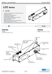
LCC Series - Pulsotronic GmbH & Co. KG
LCC Series - Pulsotronic GmbH & Co. KG
LCC Series - Pulsotronic GmbH & Co. KG
Create successful ePaper yourself
Turn your PDF publications into a flip-book with our unique Google optimized e-Paper software.
<strong>LCC</strong> <strong>Series</strong> • Laser <strong>Co</strong>py <strong>Co</strong>unters<br />
<strong>Pulsotronic</strong> <strong>GmbH</strong> & <strong>Co</strong>. <strong>KG</strong><br />
Neue Schichtstraße 14 b<br />
D-09366 Niederdorf<br />
Data Sheet <strong>LCC</strong>-130<br />
Parameterization<br />
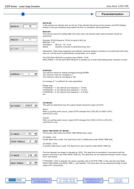
BACKLIM:<br />
In this edit-box an intensity limit can be set. If the intensity that arrives at the receiver unit DAT0 (display<br />
window in the user interface) drops below this limit, no evaluation will be performed.<br />
REGCNT:<br />
This edit-box serves for setting after how many loop runs dynamic laser diode correction should be<br />
performed.<br />
Example: SCAN frequency 15 kHz is equal to 66.6 μs<br />
REGCNT = 75<br />
Calculation: 66.6 μs * 75 = 5 ms<br />
Result: Dynamic correction is performed every 5ms<br />
Explanation: Flatly rising magazines are detected, because dynamic correction is not performed with every<br />
loop run, and the jump is automatically compensated, so to speak.<br />
The EDIT-BOX REGCNT is enabled when PMOD = DYN.<br />
When PMOD = FIX the EDIT-BOX REGCNT is disabled as no laser transmitting power correction is done.<br />
AVERAGE:<br />
This edit-box serves for setting averaging through NORM.<br />
The minimum value for averaging is 1.<br />
The maximum value for averaging is 128.<br />
An average of 1 is sufficient for most applications.<br />
Please note:<br />
If AVERAGE = 1, the internal scan frequency = 15 kHz.<br />
If AVERAGE = 2, the internal scan frequency = 7.5 kHz.<br />
If AVERAGE = 4, the internal scan frequency = 3.75 kHz.<br />
etc.<br />
OUTMODE:<br />
This edit-box determines how the output impulse should be output at OUT0:<br />
Direct:<br />
When a counting event occurs, output OUT0 changes from LOW (0V) to HIGH (+24V),<br />
until HOLD is over.<br />
Inverse:<br />
When a counting event occurs, output OUT0 changes from HIGH (+24V) to LOW (0V),<br />
until HOLD is over.<br />
DEAD TIME MODE (DT MODE):<br />
This function field shows the DEAD TIME MODE that is used.<br />
DT MODE = FIX:<br />
A fixed dead time is used. The dead time is set in milliseconds under DEAD TIME [ms].<br />
DT MODE = DYN:<br />
A dynamic dead time is used. The dead time is set in percent under DEAD TIME [%].<br />
The time between two edges is valuated as 100%. The dead time is calculated in accordance with the<br />
percent value that is set under DEAD TIME [%]. The dead time can be measured through monitor output<br />
OUT1 (low-active).<br />
If TRIGGER = EXT is selected, the sensor operates with an ACTIVE TIME. In this case the input fields<br />
DEAD TIME MODE and DEAD TIME [...] are disabled. The active time can be measured through monitor<br />
output OUT1 (low-active).<br />
Tel.: 037296 / 930 200<br />
Fax.: 037296 / 930 280<br />
vertrieb@pulsotronic.de<br />
www.pulsotronic.de<br />
Änderungen<br />
vorbehalten!


