Installation information IND4x9 / BBA4x9 - METTLER TOLEDO
Installation information IND4x9 / BBA4x9 - METTLER TOLEDO
Installation information IND4x9 / BBA4x9 - METTLER TOLEDO

Create successful ePaper yourself
Turn your PDF publications into a flip-book with our unique Google optimized e-Paper software.
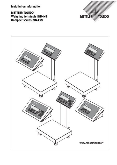
IND 429<strong>Installation</strong> <strong>information</strong><strong>METTLER</strong> <strong>TOLEDO</strong>Weighing terminals <strong>IND4x9</strong>Compact scales <strong>BBA4x9</strong>IND 449IND 439www.mt.com/support
Congratulations on choosing the quality and precision of <strong>METTLER</strong> <strong>TOLEDO</strong>. Properuse according to this <strong>Installation</strong> <strong>information</strong> and regular calibration and maintenanceby our factory-trained service team ensure dependable and accurate operation,protecting your investment. Contact us about a ServiceXXL agreement tailored toyour needs and budget.We invite you to register your product at www.mt.com/productregistration so we cancontact you about enhancements, updates and important notifications concerningyour product.
<strong>IND4x9</strong> / <strong>BBA4x9</strong>ContentsContentsPage1 General <strong>information</strong>..................................................................... 42 Safety instructions....................................................................... 52.1 Safety instructions for explosion protected weighing terminals<strong>IND4x9</strong>xx .................................................................................... 52.2 Safety instructions for non-explosion-protected devices ..................... 73 Commissioning ........................................................................... 83.1 Connecting analog weighing platforms............................................ 83.2 Connecting IDNet weighing platforms.............................................. 103.3 Setting up the compact scale ......................................................... 113.4 Particular points when commissioning explosion protectedweighing terminals ....................................................................... 123.5 Connecting devices with a 12–24 V DC supply ................................ 124 Scale configuration...................................................................... 134.1 Calling up the service menu........................................................... 134.2 Overview ..................................................................................... 144.3 Service menu operation ................................................................. 144.4 Description of the service menu...................................................... 155 Commissioning and configuration of the interfaces........................ 205.1 Configuration and testing of the Ethernet interface ............................. 205.2 Installing the drivers for the USB interface......................................... 215.3 Configuration of the WLAN interface ................................................ 226 Structure of an analog weighing system........................................ 256.1 Selection of the weighing cell(s)..................................................... 256.2 Measurement range of the terminals................................................ 287 Technical data............................................................................. 297.1 General technical data................................................................... 297.2 Technical data of the analog scale interface..................................... 307.3 Assignment of the interface connections .......................................... 31<strong>Installation</strong> <strong>information</strong> 22013821A 04/06 3
General <strong>information</strong><strong>IND4x9</strong> / <strong>BBA4x9</strong>1 General <strong>information</strong>DocumentationThe device is supplied with a CD containing the complete documentation on the<strong>IND4x9</strong> / <strong>BBA4x9</strong> series.These installation instructions provide <strong>information</strong> on installing and commissioningthe entire series.<strong>IND4x9</strong> / <strong>BBA4x9</strong> weighing terminals and compact scalesWeighing terminalsCompact scalesNormal versionIND429IND439IND449IND439checkIND449check+BBA429BBA439checkBBA449check+Explosion protectedversionIND429xxIND439xxIND449xxIND439xx checkIND449xx check+–Power supply variantsBuilt-in power supplyunitNormal versionStandardExplosion protectedversionStandardBuilt-in storage battery Optional OptionalExternal power supply12–24 V DCVia external storagebatteryOptionalOptionalOptional (<strong>BBA4x9</strong>) –4 <strong>Installation</strong> <strong>information</strong> 22013821A 04/06
<strong>IND4x9</strong> / <strong>BBA4x9</strong>Safety instructions2 Safety instructions2.1 Safety instructions for explosion protected weighing terminals<strong>IND4x9</strong>xxThe device fulfils Device category 3 and is approved for operation in Zone 2 (gases)and Zone 22 (dusts) hazardous areas.There is an increased risk of injury and damage when used in hazardous areas.Special care must be taken when working in such hazardous areas. The code ofpractice is oriented to the "Safe Distribution" concept drawn up by <strong>METTLER</strong> <strong>TOLEDO</strong>.CompetenceEx approval▲ The device, accompanying weighing platforms and accessories may only beinstalled, maintained and repaired by authorised <strong>METTLER</strong> <strong>TOLEDO</strong> servicepersonnel.▲ The mains connection may only be connected or disconnected by the owner’selectrician.▲ For the exact specification please refer to the statement of conformity.▲ No modifications may be made to the terminal and no repair work may beperformed on the modules. Any weighing platform or system modules that areused must comply with the specifications contained in the installation instructions.Non-compliant equipment jeopardizes the safety of the system, cancels the Exapproval and renders any warranty or product liability claims null and void.▲ The cable glands must be tightened so that a strain relief of ≥ 20 N per mm cablediameter is ensured.▲ Ensure that the supply voltage at the installation site amounts to 230 V.▲ When connecting external devices, always observe the maximum permissibleconnected loads, see Page 29. It must be ensured that no voltages are fed intothe device than it itself provides. The interface parameters have to fulfil thestandard.▲ Peripheral devices without an Ex approval may only be operating in nonhazardousareas. It must be ensured that no voltages are fed into the device thanit itself provides. In addition the maximum permissible connected loads have tobe observed, see Page 29. The interface parameters have to fulfil the standard.▲ The safety of a weighing system is only guaranteed when the weighing system isoperated, installed and maintained in accordance with the respectiveinstructions.▲ Also comply with the following:– the instructions for the system modules– the regulations and standards in the respective country– the statutory requirement for electrical equipment installed in hazardous areasin the respective country– all instructions related to safety issued by the owner▲ Before initial start-up and following service work, check the explosion-protectedweighing system for the proper condition of all safety-related parts.<strong>Installation</strong> <strong>information</strong> 22013821A 04/06 5
Safety instructions<strong>IND4x9</strong> / <strong>BBA4x9</strong><strong>Installation</strong> andretrofittingOperation▲ Only install or perform maintenance work on the weighing terminal,accompanying weighing platforms and accessories in the hazardous zone if thefollowing conditions are fulfilled:– the owner has issued a permit ("spark permit" or "fire permit"),– the area has been rendered safe and the owner's safety co-ordinator hasconfirmed that there is no danger,– the necessary tools and any required protective clothing are provided (dangerof the build-up of static electricity).▲ The certification papers (certificates, manufacturer’s declarations) must bepresent.▲ Connection values of externally connectable devices and cables of othermanufacturers must be known, e.g. capacitances, inductances and currentconsumption.▲ Lay cables in such a way that they are protected from damage.▲ Only route cables into the housing of the system modules via the earthing cablegland or <strong>METTLER</strong> <strong>TOLEDO</strong> plug and ensure proper seating of the seals. Ensurethat the cable shields are connected correctly and that they have a secureconnection to the housing.▲ If the device is used in conjunction with an automatic or manual filling plant, allof the system modules must be equipped with a permanently wired emergencystop circuit, independent of the system circuit, in order to prevent personal injuryor damage to other items of equipment.▲ Establish an equipotential bonding.▲ If the weighing platforms are installed in a pit, test whether primary explosionprotection is required.▲ Cover unused connection sockets with protective caps.▲ Mount the labelling for operation in hazardous areas, see Section 3.4.3.▲ After connectors have been mounted, screw on the securing clamps for externalconnectors.▲ Prevent the build-up of static electricity. Therefore:– Always wear suitable working clothes when operating or performing servicework on the system.– Do not rub or wipe off the keyboard surface with a dry cloth or glove.▲ Do not use protective hoods.▲ Prevent damage to the weighing terminal. Hairline cracks in the keyboardmembrane are also considered damage.▲ If the weighing terminal, accompanying weighing platforms or accessories aredamaged:– Switch off the weighing terminal– Separate the weighing terminal from the mains in accordance with theapplicable regulations– Secure the weighing terminal against accidental start-up▲ Always charge the storage batteries in a safe zone.6 <strong>Installation</strong> <strong>information</strong> 22013821A 04/06
<strong>IND4x9</strong> / <strong>BBA4x9</strong>Safety instructions2.2 Safety instructions for non-explosion-protected devices▲ Do not use the device in a hazardous environment!Special devices are available in our range of products for hazardousenvironments.▲ Ensure that the power socket outlet for the device is earthed and easilyaccessible, so that it can be de-energized rapidly in emergencies.▲ Ensure that the supply voltage at the installation site lies within in the range of100 V to 240 V.▲ The safety of the device cannot be ensured if it is not operated in accordance withthese operating instructions.▲ Only authorised personnel may open the device.▲ Check the power cable regularly for damage. If it is damaged, disconnect thedevice immediately from the power supply.▲ Ensure that there is a space of at least 3 cm at the rear in order to prevent thepower cable from being bent too strongly.<strong>Installation</strong> <strong>information</strong> 22013821A 04/06 7
Commissioning<strong>IND4x9</strong> / <strong>BBA4x9</strong>3 Commissioning3.1 Connecting analog weighing platformsAny analog weighing platforms that fulfil the required specifications can be connectedto weighing terminals with an analog weighing interface, see Section 7.2.Weighing platforms for hazardous areas require the corresponding approval.3.1.1 Information on the weighing cellsWeighing cells with or without SENSE cables➜ In the case of cells without SENSE cables short-circuit the connections +Ex(Excitation) and +Se (Sense) or –Ex and –Se at the connector or at theconnection terminal.Cells without SENSE cables+Ex+SeCells with SENSE cablesrequired for certifiable weighing systems+Ex+Se+Si+Si–Si–Se–Ex–Si–Se–Ex3.1.2 Connection of weighing platforms with several weighing cellsUp to four weighing cells can be connected to a weighing terminal in parallel. Ajunction box is usually used to connect several weighing cells.The sum of the nominal capacities of the individual cells corresponds to the totalcapacity of the weighing system. When entering the scale capacities in the menu(Section 4.4.5), select values in such a way that the individual cells cannot beoverloaded.3.1.3 Preparation of the weighing platform connection cable135 mm15 mm5mm➜ Strip the cell cable in accordance with the figure.8 <strong>Installation</strong> <strong>information</strong> 22013821A 04/06
<strong>IND4x9</strong> / <strong>BBA4x9</strong>Commissioning3.1.4 Connection of an analog weighing platform to the weighing terminalThe weighing terminals IND439 / IND439xx and IND449 / IND449xx can beequipped with a second analog weighing interface.The connection of a second weighing platform requires that a weighing platformalready be connected directly to the weighing terminal.DANGER OF ELECTRIC SHOCK➜ Disconnect the weighing terminal from the power supply before beginninginstallation work.123Opening the weighing terminal and drawing in the weighing platform cable1. In the case of explosion protected weighing terminals remove the plug protectionstrip at the rear of the terminal.2. Open the terminal. To do so, unscrew the hex bolts and lay the cover down.When doing so, take care of the cable connections.3. Remove the cable gland of the desired scale connection and the blind plugs fromthe cable gland.4. Slide the union nut (3) and moulded seal (2) over the cable sheathing. If anybraided screen cores loosen in the process, these may not contact anyconductive system parts.5. Unbraid the exposed screen and place it evenly over the moulded seal (2).6. Insert the moulded seal with the cable into the anti-twist guard of the metalhousing (1).7. Screw the union nut onto the metal housing and tighten it.+Ex +Se +SiSi = SignalEx = ExcitationSe = Sense-Si-Se -ExConnecting the first analog weighing platform1. Pull off the green 7-pin connector in the weighing terminal. The connector has atab that facilitates its removal and plugging.2. Fasten the conductors of the connecting cable to the connector. The connectorassignment is shown in the adjacent figure.The 7-pin connector has an additional connection in the middle for the signalearth. The signal earth can optionally be applied to this connection or to thescreening and moulded seal (2).When connecting <strong>METTLER</strong> <strong>TOLEDO</strong> weighing platforms observe the connectionscheme supplied with the weighing platform.3. Plug the connector in the weighing terminal. Ensure that the connector sitsexactly centred on the socket. Otherwise not all the pins contact.<strong>Installation</strong> <strong>information</strong> 22013821A 04/06 9
Commissioning<strong>IND4x9</strong> / <strong>BBA4x9</strong>–Ex –Se –Si +Si +Se +ExNoteConnecting the second analog weighing platform(only IND439 / IND439xx and IND449 / IND449xx)➜ Connect the conductors of the connecting cable to the 7-pin terminal block on thesecond analog PCB. The terminal assignment is shown in the adjacent figure.The 7-pin terminal block has an additional connection in the middle for thesignal earth. The signal earth can optionally be applied to this connection or tothe screening.When connecting <strong>METTLER</strong> <strong>TOLEDO</strong> weighing platforms observe the connectionscheme supplied with the weighing platform.• In the factory setting the second scale is configured as a quantity scale (BULK).REF (reference scale) or AUXILIARY (auxiliary scale) can be selected instead in theCOMMUNICATION –> OPTION –> MODE interface menu. The BYPASS setting canbe used to de-activate the weighing platform.• Subsequently calibrate the second analog weighing platform (SCALE 2).Closing the terminal1. Position the cover and screw on the hex bolts. Ensure that no cables are pinchedand that the cover sealing ring is positioned correctly.2. Tighten the union nut of the heavy-gauge screw joint(s).3. In the case of explosion protected weighing terminals mount the plug protectionstrip over the connections at the rear of the terminal.3.2 Connecting IDNet weighing platformsAlternatively to the analog scale connection the weighing terminals can also beequipped with IDNet scale interfaces. At IND439/IND439xx and IND449/IND449xx asecond IDNet weighing platform can be connected optionally.Information about two-scales systemsThe scale with the higher address is defined by the weighing terminal as the secondscale, irrespective of the socket to which the scale is connected. When brand newscales are commissioned, the weighing terminal automatically assigns an address.If an IDNet scale already has an address, this can be reset in the scale service mode(RES ALL). In the process the ID code is increased at certified scales.10 <strong>Installation</strong> <strong>information</strong> 22013821A 04/06
<strong>IND4x9</strong> / <strong>BBA4x9</strong>CommissioningProcedure1. Set up the (first) weighing platform, refer to the installation instructions of theweighing platform.2. Lay the weighing platform cable to the weighing terminal.3. Ensure that the weighing terminal is switched off.4. In the case of explosion protected devices remove the plug protection strip at therear.5. Plug the weighing platform connector into the weighing terminal and tighten thescrews.6. Switch on the weighing platform. This weighing platform has the scale number 1.7. If necessary, repeat Steps 1 to 6 for the second scale. Scale number 2 isassigned to the second scale.8. In the case of explosion protected devices mount the plug protection strip over theconnections at the rear.NoteIn the factory setting the second scale is configured as a quantity scale (BULK). REF(reference scale) or AUXILIARY (auxiliary scale) can be selected instead in theCOMMUNICATION –> OPTION –> MODE interface menu. The BYPASS setting can beused to de-activate the weighing platform.3.3 Setting up the compact scale1. Set up the compact scale at the desired installation site.2. Level the compact scale; refer to the PBA430 weighing platform operatinginstructions.<strong>Installation</strong> <strong>information</strong> 22013821A 04/06 11
Commissioning<strong>IND4x9</strong> / <strong>BBA4x9</strong>3.4 Particular points when commissioning explosion protectedweighing terminals3.4.1 Equipotential bondingThe equipotential bonding must be installed by a professional electrician when usingthe weighing platforms in hazardous areas.➜ Connect equipotential bonding of all devices in accordance with the countryspecificregulations and standards. In the process, make sure that all devicehousings are connected to the same potential via the PA terminals.Weighing terminalequipotential bondingterminalThe equipotential bonding clamp of the weighing terminal is found on the COM1socket.3.4.2 Limited mobilityEXPLOSION HAZARDThe device may only be operated in Zone 2 and 22 hazardous areas.Cabling➜ Protect data and signal cable extensions against inadvertent disconnection.➜ Secure the interface connections on the rear using the plug protection strip.3.4.3 Labelling for operation in a hazardous areaThe following signs must be mounted on the weighing terminal, accompanyingweighing platforms and accessories so that they are clearly visible:• Model plate with the device’s model data, manufacturer and serial number• Safety instructions• Explosion protection identification• If appropriate, temperature range3.5 Connecting devices with a 12–24 V DC supplyExplosion protected IND429xx weighing terminals are supplied with a fixed-mounted2.5 m long connecting cable with open ends.Non-explosion-protected devices are equipped with a socket for connecting the powersupply. A connecting cable with open ends is included with the device.Connected valuesConnection endColour code12 V DC – 24 V DC, max. 800 mAOpen endsBrown – plusWhite – minus12 <strong>Installation</strong> <strong>information</strong> 22013821A 04/06
<strong>IND4x9</strong> / <strong>BBA4x9</strong>Scale configuration4 Scale configuration4.1 Calling up the service menu4.1.1 At non-certifiable analog scales and IDNet scales1. Press and hold until COdE appears.2. Enter the service password .The SCALE menu item is displayed.NoteAccess to the service menu is secured by means of a software seal (ID code) atIDNet scales. If changes are carried out at a scale that is set to certifiable, the ID codeis increased by 1 and stored in the scale. After configuration has been terminated, theID code at the connector of the scale has to be set to the same value as the storedone. This setting has to be stored by certifiable means.4.1.2 At certifiable analog scalesDue to metrological regulations direct access to the service menu (technician mode)is blocked at certified or certifiable scales. The calibration seal is destroyed when thedevice is opened. After the configuration has been completed, the device has to berecalibrated by an authorised company and a new calibration seal attached before itmay be used again as a calibrated scale.DANGER OF ELECTRIC SHOCKThe power supply unit under the power supply unit cover is energized.➜ Do not carry out service work on the power supply unit and mains cable.1Procedure1. Devices with power connection: Disconnect from the power supply. Devices withstorage battery: Switch off.2. Open the housing cover.3. Remove the cover and set it down or fix it. When doing so, take care of the cableconnections.4. Devices with power connection: Connect to the power supply. Devices withstorage battery: Switch on.5. Press the Pushbutton 1 on the PCB of the first scale interface. Use a suitable toolto this purpose, for example, the blunt end of a pencil.The device starts up and the first block of the SCALE servicemenu is displayed.6. Replace the cover and carry out the service settings.7. After the settings have been completed, disconnect the power plug again atdevices with a power connection.8. Close the housing cover with the hex bolts. Ensure proper seating of the coversealing ring when doing so.<strong>Installation</strong> <strong>information</strong> 22013821A 04/06 13
Scale configuration<strong>IND4x9</strong> / <strong>BBA4x9</strong>4.2 OverviewAfter the service menu has been called up, the entire menu is available, also the userand supervisor menu. The following overview shows the SCALE menu block, theremaining menu is described in the operating instructions.NoteOnly the menu blocks in bold are displayed at IDNet scales. At IDNet scales theservice mode of the scale is shown after SCALE (1/2) has been selected. The queryrEtUrN? appears. With SNr is displayed as the next menu item.Block Meaning PageSCALE MEtrOLO Determining the admissibility for certification 15SCALE 1 /SCALE 2Selection of the scale to be configured, is only displayed at two-scalesystemsrAMP Display of the excursion of the A/D converter (ramp) 15SNr Query/Modification of the serial number 15SCAL.bLd Input of the configuration data 16GEO Setting of the Geo value 16LIN-CAL Linearization with calibration 18CAL Basic calibration 18CONtrOL Activation of the control mode 18ZErO Settings for the zero point 19Min.WEiG Setting the minimum weighing-in quantity 19154.3 Service menu operationOperation in the service menu is the same as in the user and supervisor menu.Numerical values, for example capacity, can be entered via the numerical keypad, ifpresent.Numerical input at devices without number block1. Press the T key in order to activate the input.The first number begins to flash.2. Change the number using the and T keys.3. Confirm the modified number with the key.The next number begins to flash.4. Repeat Steps 2 and 3 until all the numbers have been entered.14 <strong>Installation</strong> <strong>information</strong> 22013821A 04/06
<strong>IND4x9</strong> / <strong>BBA4x9</strong>Scale configuration4.4 Description of the service menu4.4.1 Admissibility for certificationMEtrOLONO APPrOIMLntEPNoteSetting the admissibility for certificationScale not certifiableCertify scale to OIMLCertify scale to NTEP, valid for the USAIf a scale is certified, various scale settings are no longer available or are onlyavailable to a limited extent. Direct access to the menu for service personnel is,furthermore, blocked subsequently.4.4.2 SCALE1/SCALE2 – Selecting a scaleThis menu item appears only if a second scale or weighing platform is connected.4.4.3 Querying the value of the A/D converterrAMPrMP 20NoteDisplay of the percentage deflection of the analog/digital converter (ramp)This value can be used to determine whether the weighing cell operates correctly.Scales with identical and a weighing cell that functions correctly have more or lessthe same ramp values. The value is dynamic and changes when the load changes.4.4.4 Querying the serial number of the terminal or compact scaleSNrNote1234567 Display or modification of the serial number.The serial number should not be changed except, for example, after a new mainprinted circuit board has been installed.<strong>Installation</strong> <strong>information</strong> 22013821A 04/06 15
Scale configuration<strong>IND4x9</strong> / <strong>BBA4x9</strong>4.4.5 Entering configuration dataSCAL.bLdSCAL.tYPbAS.UNItSCL.CAPrESOLNoteInput of the configuration dataDefining the scale typeSINGLE.r Single Range: Single-range scale2MULt.IN Multi interval: Scale with rough range and 1 shiftable fine range.Automatic switching between the ranges in both directions.2MULt.rN Multi Range: Scale with rough range and 1 fixed fine range.Automatic change to the rough range. Return to the fine range atzero pass.3MULt.IN Multi Interval: Scale with rough range and 2 shiftable fine ranges3MULt.rN Multi Range: Scale with rough range and 2 fixed fine ranges.Specify the basic unit for entering in the service menug Gramskg Kilogramsoz Ounceslb Poundst TonsEntry of the scale capacity in the selected basic unitSelection of the resolution in the selected basic unitThe available resolutions depend on the capacity of the weighing system.In case of multi-range or multi-interval scales the blocks SCL.CAP and rESOLare available separately for each range.They are displayed in the following sequence:SCL.CAP 1, rESOL 1, SCL.CAP 2, rESOL 2, SCL.CAP 3, rESOL 34.4.6 Setting the Geo valueGEOThe Geo value is used to adapt the weighing system to the local gravity conditions.0 ... 31 Setting range: 0 ... 31, see following table16 <strong>Installation</strong> <strong>information</strong> 22013821A 04/06
<strong>IND4x9</strong> / <strong>BBA4x9</strong>Scale configurationNorthern or southern latitude in degreesand minutesTable of Geo valuesHeight above sea level in meters0325325650650975Height above sea level in feet01060106021302130320097513003200426013001625426053301625195053306400195022756400746022752600746085302600292585309600292532509600106600° 0’ – 5° 46’ 5 4 4 3 3 2 2 1 1 0 05° 46’ – 9° 52’ 5 5 4 4 3 3 2 2 1 1 09° 52’ – 12° 44’ 6 5 5 4 4 3 3 2 2 1 112° 44’ – 15° 6’ 6 6 5 5 4 4 3 3 2 2 115° 6’ – 17° 10’ 7 6 6 5 5 4 4 3 3 2 217° 10’ – 19° 2’ 7 7 6 6 5 5 4 4 3 3 219° 2’ – 20° 45’ 8 7 7 6 6 5 5 4 4 3 320° 45’ – 22° 22’ 8 8 7 7 6 6 5 5 4 4 322° 22’ – 23° 54’ 9 8 8 7 7 6 6 5 5 4 423° 54’ – 25° 21’ 9 9 8 8 7 7 6 6 5 5 425° 21’ – 26° 45’ 10 9 9 8 8 7 7 6 6 5 526° 45’ – 28° 6’ 10 10 9 9 8 8 7 7 6 6 528° 6’ – 29° 25’ 11 10 10 9 9 8 8 7 7 6 629° 25’ – 30° 41’ 11 11 10 10 9 9 8 8 7 7 630° 41’ – 31° 56’ 12 11 11 10 10 9 9 8 8 7 731° 56’ – 33° 9’ 12 12 11 11 10 10 9 9 8 8 733° 9’ – 34° 21’ 13 12 12 11 11 10 10 9 9 8 834° 21’ – 35° 31’ 13 13 12 12 11 11 10 10 9 9 835° 31’ – 36° 41’ 14 13 13 12 12 11 11 10 10 9 936° 41’ – 37° 50’ 14 14 13 13 12 12 11 11 10 10 937° 50’ – 38° 58’ 15 14 14 13 13 12 12 11 11 10 1038° 58’ – 40° 5’ 15 15 14 14 13 13 12 12 11 11 1040° 5’ – 41° 12’ 16 15 15 14 14 13 13 12 12 11 1141° 12’ – 42° 19’ 16 16 15 15 14 14 13 13 12 12 1142° 19’ – 43° 26’ 17 16 16 15 15 14 14 13 13 12 1243° 26’ – 44° 32’ 17 17 16 16 15 15 14 14 13 13 1244° 32’ – 45° 38’ 18 17 17 16 16 15 15 14 14 13 1345° 38’ – 46° 45’ 18 18 17 17 16 16 15 15 14 14 1346° 45’ – 47° 51’ 19 18 18 17 17 16 16 15 15 14 1447° 51’ – 48° 58’ 19 19 18 18 17 17 16 16 15 15 1448° 58’ – 50° 6’ 20 19 19 18 18 17 17 16 16 15 1550° 6’ – 51° 13’ 20 20 19 19 18 18 17 17 16 16 1551° 13’ – 52° 22’ 21 20 20 19 19 18 18 17 17 16 1652° 22’ – 53° 31’ 21 21 20 20 19 19 18 18 17 17 1653° 31’ – 54° 41’ 22 21 21 20 20 19 19 18 18 17 1754° 41’ – 55° 52’ 22 22 21 21 20 20 19 19 18 18 1755° 52’ – 57° 4’ 23 22 22 21 21 20 20 19 19 18 1857° 4’ – 58° 17’ 23 23 22 22 21 21 20 20 19 19 1858° 17’ – 59° 32’ 24 23 23 22 22 21 21 20 20 19 1959° 32’ – 60° 49’ 24 24 23 23 22 22 21 21 20 20 1960° 49’ – 62° 9’ 25 24 24 23 23 22 22 21 21 20 2062° 9’ – 63° 30’ 25 25 24 24 23 23 22 22 21 21 2063° 30’ – 64° 55’ 26 25 25 24 24 23 23 22 22 21 2164° 55’ – 66° 24’ 26 26 25 25 24 24 23 23 22 22 2166° 24’ – 67° 57’ 27 26 26 25 25 24 24 23 23 22 2267° 57’ – 69° 35’ 27 27 26 26 25 25 24 24 23 23 2269° 35’ – 71° 21’ 28 27 27 26 26 25 25 24 24 23 2371° 21’ – 73° 16’ 28 28 27 27 26 26 25 25 24 24 2373° 16’ – 75° 24’ 29 28 28 27 27 26 26 25 25 24 2475° 24’ – 77° 52’ 29 29 28 28 27 27 26 26 25 25 2477° 52’ – 80° 56’ 30 29 29 28 28 27 27 26 26 25 2580° 56’ – 85° 45’ 30 30 29 29 28 28 27 27 26 26 2585° 45’ – 90° 00’ 31 30 30 29 29 28 28 27 27 26 26325035751066011730<strong>Installation</strong> <strong>information</strong> 22013821A 04/06 17
Scale configuration<strong>IND4x9</strong> / <strong>BBA4x9</strong>4.4.7 Linearization with simultaneous calibrationLIN-CAL3 POINt /5 POINtA basic calibration must have been carried out at least once for linearization withsimultaneous calibration.➜ If available, apply the preload.• 3-point linearization (by default at 0 %, 50 % and 100 % of the full load)• 5-point linearization (by default at 0 %, 25 %, 50 %, 75 % and 100 % of thefull load)1. Confirm the type of linearization.The display begins to flash, the scale determines the zero point automatically.The scale next requests the first weight.2. If appropriate, change the displayed weight value.3. Place the displayed weight on the scale and confirm with .4. Repeat Steps 2 and 3 for each additional sample.After all the weights have been applied, donE is displayed.Notes • Determining the zero point can be skipped by pressing T . In this case theexisting zero point is used as the reference.• Linearization/calibration can be cancelled at any time with thekey.4.4.8 Basic calibrationCALCalibration can be carried out with preload in basic calibration.PrELOAd 1. Load the desired preload and confirm with .The scale next requests the calibration weight corresponding to the full load.2. If appropriate, change the displayed weight value.3. Place the displayed weight on the scale and confirm with .After calibration has been carried out, donE is displayed.Notes • Determining the preload can be skipped with T . In this case the existing zeropoint is used as the reference.• Calibration can be cancelled at any time with the key.• In order to achieve particularly high precision carry out calibration under fullload.4.4.9 Activating the control modeCONtrOLIn control mode the current weighing result is displayed with a high resolution andwithout a weight unit. This allows the scale to be checked, for example aftercalibration and/or linearization.18 <strong>Installation</strong> <strong>information</strong> 22013821A 04/06
<strong>IND4x9</strong> / <strong>BBA4x9</strong>Scale configuration4.4.10 Settings for the zero pointZErOZ-CAPtSEt.ZErOSettings for the zero pointSpecify the zero capturing range-2 18 Zero capturing range –2 % to +18 %–2 2 Zero capturing range –2 % to +2 %, mainly for certifiable scalesMove the calibration zero point. This is necessary if an auxiliary preload is used orif the preload (for example roller conveyor) cannot be used for calibration or if theylie outside the zero capturing range.NoteAZM1. Apply the preload and confirm with .The query SUrE is displayed.2. Confirm moving of the zero point with or cancel with T .3. If underload or overload is displayed after the menu has been exited, switch thedevice off and on again.Setting for the automatic zero compensation mode, refer to the operatinginstructions.The zero capturing range limits the nominal capacity of the scale. If the capacity ofa weighing cell is to be used to its complete extent, the zero capturing range can belimited to –2 % to +2 %.4.4.11 Specifying the minimum weighing-in quantityMin.WEiGEntry of the minimum weighing-in quantity in the selected basic unit.When the minimum weighing-in quantity is activated, * is displayed if the weight onthe scale falls below the stored minimum weight.<strong>Installation</strong> <strong>information</strong> 22013821A 04/06 19
Commissioning and configuration of the interfaces<strong>IND4x9</strong> / <strong>BBA4x9</strong>5 Commissioning and configuration of the interfaces5.1 Configuration and testing of the Ethernet interface5.1.1 Configuration of the Ethernet interface in the menu of <strong>IND4x9</strong> / <strong>BBA4x9</strong>The configuration of the Ethernet interface in the menu is described in the operatinginstructions (COMMUNI –> OPTION –> ETHERNET).Ask your network administrator for the correct settings for the IP address, subnetmask and gateway.5.1.2 Establishing a network connection between the Ethernet interface and the PCIf the PC is already connected via a switch/hub to the network, no further settings arerequired for the network card in the PC.In the case of a direct connection between the Ethernet interface and the PC via across-patch cable the settings for the TCP/IP Internet protocol have to be observed.1. Call up Start –> Control Panel –> Network Connection.2. Select "Local Area Connection" and right-click it to select "Properties".3. Select "Internet Protocol (TCP/IP)" and click "Properties".4. Enter the IP address, subnet mask and gateway in accordance with the settingsin the menu.5.1.3 Testing the Ethernet interfaceThe "Ping" command can be used to check whether a user exists in the network andcan also be addressed.1. Open a DOS box (command prompt) at the PC (Start –> Run).2. Enter the "Ping" command followed by the IP address at the weighing terminal orcompact scale.With the default address the command is as follows: Ping 192.168.1.13. The answer is, for example, Bytes = 32, Time = 2 ms, TTL = 64.If no response appears, repeat the command with correct entries.5.1.4 Establishing a connection with HyperTerminal1. Select the DIALOG setting for the Ethernet interface in the menu under COMMUNI–> COM2 –> MODE.2. Start HyperTerminal and create a new connection.3. Select "TCP/IP (Winsock)", specify the IP address of the Ethernet interface(factory setting: 192.168.1.1) enter the port number (factory setting: 8000).4. Select the following settings under "File –> Properties –> Settings –> ASCIIConfiguration":– Transmitted characters end with line feed– Output entered characters locally (local echo)– Write lines that are too long in the terminal windowSICS commands can now be transmitted at the weighing terminal or compact scale.20 <strong>Installation</strong> <strong>information</strong> 22013821A 04/06
<strong>IND4x9</strong> / <strong>BBA4x9</strong>Commissioning and configuration of the interfaces5.1.5 Configuration of the Ethernet interface via a Web browserThe Ethernet interface is equipped with a Web server through which the furthersettings can be carried out.1. Start a Web browser on the PC, for example Internet Explorer, and enter "http://192.168.1.1" as the target address.The starting page of the Ethernet Web server is displayed.2. Use the "Client Server –> Help" menu item to call up further <strong>information</strong> on settingthe Ethernet interface.5.2 Installing the drivers for the USB interfaceFor weighing terminals or compact scales with a USB interface a CD with the requireddrivers is provided additionally. The drivers are installed in two steps.The following section describes the installation for a PC with Windows XP.5.2.1 Installing USB drivers1. Connect the USB interface of the weighing terminal or compact scale to the PCwith a USB cable.The message "New hardware found" is displayed at Windows XP.2. Insert the supplied CD into the PC.The wizard for searching for new hardware is displayed.3. Select "Install software from a list or specific location (for advanced users)" in theinitial screen and click "Next".4. In the next step select "Browse removable media (floppy disk, CD, etc.)" andclick "Next".The required files are searched for and copied.A warning is displayed since the drivers on the CD ROM have not been certified byMicrosoft WHQL. However, the drivers were tested extensively by <strong>METTLER</strong> <strong>TOLEDO</strong>and are suitable for installation under Windows XP.5. Click "Continue Anyway".6. Click "Finish" in the next screen.The installation is completed. The message "New hardware found" is displayed.Subsequently The VCP driver still has to be installed subsequently.5.2.2 Installing VCP driversThe wizard for searching for new hardware is displayed again.➜ Repeat Steps 3 to 6 as described under Section 5.2.1 for the VCP driver.<strong>Installation</strong> <strong>information</strong> 22013821A 04/06 21
Commissioning and configuration of the interfaces<strong>IND4x9</strong> / <strong>BBA4x9</strong>5.2.3 Setting the Virtual COM Port (VCP)The installation of the VCP driver makes an additional serial interface available on thePC. This interface can be used to access weighing terminals or compact scales witha USB interface.1. Call up "Start –> Control Panel" and double-click "System".2. Select the "Hardware" tab and click the "Device Manager".3. Search for the entry "Ports (COM & LPT)" and click the adjacent "+" symbol.All the available ports are displayed.4. Double-click "<strong>METTLER</strong> <strong>TOLEDO</strong> Serial Port".The "Properties of <strong>METTLER</strong> <strong>TOLEDO</strong> Serial Port" screen is displayed.5. Select the "Port settings" tab and click "Advanced".6. Select the desired COM port number from the drop-down menu list and confirmwith "OK".5.2.4 Establishing a connection with HyperTerminal1. Select the DIALOG setting for the USB interface in the menu under COMMUNI –>COM2 –> MODE.2. Start HyperTerminal and create a new connection.3. Select the desired COM port number and carry out the following settings:9600 bits/s, 8 data bits, no parity, protocol Xon/X0ff.4. Select the following settings under "File –> Properties –> Settings –>ASCII Configuration":– Transmitted characters end with line feed– Output entered characters locally (local echo)– Write lines that are too long in the terminal windowSICS commands can now be transmitted at the weighing terminal or compact scale.5.3 Configuration of the WLAN interfaceThe following section describes the installation for a PC with Windows XP. It isassumed that the WLAN interface of the weighing terminal or compact scale is in thestate of delivery with the following network parameters:IP address 192.168.0.1Subnet 255.255.255.0Gateway 0.0.0.05.3.1 Configuration of the WLAN interface in the menu of <strong>IND4x9</strong> / <strong>BBA4x9</strong>The configuration of the WLAN interface in the menu is described in the operatinginstructions (COMMUNI –> OPTION –> WLAN).Ask your network administrator for the correct settings for the IP address, subnetmask and gateway in the encrypted company network.22 <strong>Installation</strong> <strong>information</strong> 22013821A 04/06
<strong>IND4x9</strong> / <strong>BBA4x9</strong>Commissioning and configuration of the interfaces5.3.2 Establishing an ad-hoc connection to the WLAN network1. Ensure that the weighing terminal or the compact scale with the WLAN interfaceis switched off.2. Call up the WLAN configuration program on the PC and carry out the followingsettings.– Set the SSID to "Connect".– Select no encryption.– Set the parameters for the ad-hoc connection: 2.4 GHz, 11 Mbps.– Ensure that a free channel is used or that the channel is selected automatically.– Ensure that no WLAN connection is active.3. Ensure that no further network connections are active, for example LANconnection via Ethernet cable.4. Call up Start –> Control Panel –> Network Connection.5. Select "Wireless Network Connection" and click "Internet Protocol (TCP/IP)".6. Click "Properties" and carry out the following settings:– Set the IP address 192.168.0.10.A different IP address can also be selected in the subnet 192.168.0.x. The IPaddress of the weighing terminal or compact scale with WLAN interface(192.168.0.1) may not be selected.– Subnet mask: 255.255.255.0.– No gateway setting7. Call up the WLAN configuration program on the PC and activate the WLANconnection.8. Switch on the weighing terminal or compact scale with WLAN interface.The WLAN interface is equipped with a Web server through which the further settingscan be carried out.5.3.3 Configuration via Web browser1. When an active ad-hoc connection is displayed at the PC, start a Web browseron the PC, for example the Internet Explorer.2. Enter the target address "http://192.168.0.1".The log-on page of the WLAN Web user interface is displayed.3. Log on with the user name "admin" and the password "admin".4. Carry out the network settings for the encrypted company network underConfiguration –> Network.<strong>Installation</strong> <strong>information</strong> 22013821A 04/06 23
Commissioning and configuration of the interfaces<strong>IND4x9</strong> / <strong>BBA4x9</strong>5.3.4 Establishing a connection with HyperTerminal1. Select the DIALOG setting for the WLAN interface in the menu under COMMUNI –>COM2 –> MODE.2. Start HyperTerminal and create a new connection.3. Select "TCP/IP (Winsock)", specify the IP address of the WLAN interface (factorysetting: 192.168.0.1) and enter the port number (factory setting: 2101).4. Select the following settings under "File –> Properties –> Settings –> ASCIIConfiguration":– Transmitted characters end with line feed– Output entered characters locally (local echo)– Write lines that are too long in the terminal windowSICS commands can now be transmitted at the weighing terminal or compact scale.24 <strong>Installation</strong> <strong>information</strong> 22013821A 04/06
<strong>IND4x9</strong> / <strong>BBA4x9</strong>Structure of an analog weighing system6 Structure of an analog weighing system6.1 Selection of the weighing cell(s)The following data are required to determine the capacity of the weighing cell:• Scale capacity – Usually corresponds to the heaviest weighing sample that is tobe weighed using the weighing system.• Preload – Contains the total weight of all the parts that lie on the weighing cell.These include the top section of the weighing platform, the weighing pan and allthe assemblies, such as a roller conveyor, weighing vessel etc.• Total zero setting range – Consists of the desired activation zero capturing range(+18/–2 % or +/–2 %) and the zero setting range available to the user throughthe key (2 %). The total zero-set range thus amounts to either 20 % or 4 %of the scale capacity.The addition of the scale capacity, preload and total zero setting range results in therequired capacity of the weighing cell. It is advisable to include an additional safetymargin in order to avoid overloading of the weighing cell..Total capacity of the weighing cell(s) = Scale capacity + Preload + Total zero setting range + Safety marginIn the case of systems with several weighing cells divide the determined totalcapacity by the number of cells in order to determine the capacity of the individualcell. A sufficiently large safety margin is particularly important if a strong load is to beexpected in the corner areas of the scale so that the load is no longer distributedevenly amongst all the cells.In the case of systems with a lever mechanism divide the determined total capacityby the transmission ratio of the lever mechanism in order to determine the capacity ofthe individual cell.Take the following further parameters into consideration when selecting the weighingcell(s):• The smallest desired display step• Requirements for admissibility for certification, if necessary• Number and type of the weighing ranges• The approval for hazardous areas in the case of explosion protected weighingsystems<strong>Installation</strong> <strong>information</strong> 22013821A 04/06 25
Structure of an analog weighing system<strong>IND4x9</strong> / <strong>BBA4x9</strong>The terminal provides a supply voltage of 8.2 V for the weighing cell(s). Dependingon the sensitivity of the weighing cell this results in the following maximum weighingsignal (product of supply voltage and sensitivity):Sensitivity of the cell 2 mV/V 3 mV/VSupply voltage 8.2 V 8.2 VMax. weighing signal * 16.4 mV 24.6 mV *Min. weighing signal per display step (for certifiable scales) 0.5 µV/e0.5 µV/e* Only 20 mV can be measured by the A/D converter. Therefore the max. weighingcapacity may not exceed 81 % of the cell capacity.26 <strong>Installation</strong> <strong>information</strong> 22013821A 04/06
<strong>IND4x9</strong> / <strong>BBA4x9</strong>Structure of an analog weighing systemHow do I set up myscale?Application– simple weighing IND429/IND429xx– simple counting IND439x/IND439xx– simple IND439check/checkweighing IND439xx check– convenient counting IND449/IND449xx– convenient IND449check/checkweighing IND449xx check– 2 scale countingsystemAnalog optionScale parameters:– heaviest weight?– weight of pan holder?– smallest display step?– certified scale?– 1 or 2 ranges/intervals?Required cell capacityE min=Max + E 0+ Max * E N100NData of weighing cellExample A:OIML R60: C3E max(=E): 10 kgn LC(=n): 3000V min: E max/7500C N(=S):2mV/VData of terminal(acc. to certification)U e: 8.2VU min: 0.5 µV/en max: 7500eCheck(in case of several weighingranges check the finest one)U mineU e *=S * Max * 1000n * E * N>=0.5 µVeEntries in menu block“SCALE”Max –> SCL.CAPE N–> 2 - CAPtV min–> RESOL.Key:Max [kg]: weighing rangeN: no. of weighing cellsE 0[kg]: preload (weight of pan holder, container, etc.)E N[%]: zero setting range (2%) + zero capturingrange(+18/–2% or ±2%) = 20% or 4%E min[kg]: required load capacity per weighing cellData of weighing cellExample B:OIML R60: C3/30%R.C. (=E): 10kg(–> n: 3000)(–> V min: E * 30%/ nR.O. (=S): 2mV/VData of weighing cellExample C:OIML R60: C3E max(=E): 550 kgn LC(=n): 3000V min:0.01% * C nC n(=S):1.94mV/VU e[V]: power supply from terminalS [mV/V]: cell output signaln [e]: resolutionE [kg]: load capacity of selected weighing cellU min[µV/e]: minimum voltage per verification intervaln max[e]: maximum resolutionV min[g]: display step<strong>Installation</strong> <strong>information</strong> 22013821A 04/06 27
Structure of an analog weighing system<strong>IND4x9</strong> / <strong>BBA4x9</strong>6.2 Measurement range of the terminalsWhen designing a weighing system observe the measurement range of the terminalin accordance with the following overview.Total capacity of weighing cell(s)0% 100%a b c Scale capacity dDeflection of the A/D converter ("Ramp")0% 100%Weighing cell signal, range of A/D converter–4mV 0mV 16,4mV 20mVabcdTotal preload applied to the weighing cell during calibration (platform topsection, weighing pan, roller conveyor, etc.)Activation zero capturing range: +18/–2 % or +/–2 % of the weighingcapacity, can be selected in the menuZero setting range with 0 key: +/–2 % of the scale capacity, cannot bemodifiedSafety margin28 <strong>Installation</strong> <strong>information</strong> 22013821A 04/06
<strong>IND4x9</strong> / <strong>BBA4x9</strong>Technical data7 Technical data7.1 General technical dataMains connection Direct connection to power supply (supply voltage fluctuation not exceeding ±10 %of the rated voltage)• Non-explosion-protected weighing terminals <strong>IND4x9</strong>:Rated voltage 100 ... 240 V AC / 47 ... 63 Hz / 300 mAStorage battery operationIgnition protection type<strong>IND4x9</strong>xx(to IEC 60079-15)Ambient conditionsInterfacesMax. permissible connectedvalues• Explosion protected weighing terminals <strong>IND4x9</strong>xx:Rated voltage 230 V AC ±10 % / 47 ... 63 Hz / 300 mA• Compact scales <strong>BBA4x9</strong>:Rated voltage 100 ... 240 V AC / 47 ... 63 Hz / 300 mASupply at device: 24 V DC / 1.0 AIf the supply voltage is interrupted, the scale switches automatically over to storagebattery operationFor operating life refer to the operating instructions• Hazardous area Zone 2:Device category II 3G EEx nA II T4,Temperature range–10 °C ... +40 °C / 14 °F ... 104 °F• Hazardous area Zone 22:Device category II 3D IP66 T 70 °C• ApplicationIn interiors• Heightup to 2,000 m• Temperature range Class III –10 ... +40 °C / 14 ... 104 °F• Temperature range Class II0 ... +40 °C / 32 ... 104 °F• Overvoltage categoryII• Degree of soiling2• Relative humidityup to max. 80 %, non-condensing• 1 RS232 interface integrated• 1 further optional interface possible• The total of the connected values of COM1 and COM2 may not exceed 100 mA• At an installed Ethernet option COM1 may not exceed 50 mA<strong>Installation</strong> <strong>information</strong> 22013821A 04/06 29
Technical data<strong>IND4x9</strong> / <strong>BBA4x9</strong>7.2 Technical data of the analog scale interfaceAnalog scale interfaceResolutionWeighing rangesCalibrationZero setting range (key)Autozero rangeActivation zero-setrangeLinearityUnits300,000 points for non-certifiable applications7,500 points for certifiable applicationsUp to 3 weighing ranges can be defined in the menu, incl. shiftable or fixed fineranges.In the case of certifiable/certified applications the minimum voltage per calibrationvalue (0.5 µV/e) has to be ensured or 7,500 e may not be exceeded.Basic calibration and calibration during linearization2 % of the defined max. useable load, cannot be modified2 % of the defined max. useable load, cannot be modified–2 % ... 18 % or –2 % ... 2 % referenced to the defined max. useable loadcan be selected in the menu0.01 % of the defined max. useable loadg, kg, oz, lb, tNumerical steps n 1, 2, 5 x 10 n , can be selected in the menuCell power supply 8.2 VRequirements for the weighing cellNominal load 0.1 ... 999,999.9 (g, kg, lb, oz, t)Permissible impedance ≥ 80 ΩDifferential signal –1 mV ... 25 mV (see the following calculation example)Calculation example for the differential signalData of the weighing cell: Sensitivity 2 mV/V, cell capacity 100 kgDifferential signal for nominal load (60 kg)2 mV/V * 8.2 V * 60 kg/100 kg = 9.84 mVDifferential signal for half load (30 kg)2 mV/V * 8.2 V * 30 kg/100 kg = 4.92 mVPrerequisites for certifiable scales• Certifiable weighing cell with SENSE cables (6 leads),Sensitivity of the cells 2 mV/V or 3 mV/V• Scale configured in the Service menu as certifiable• Labelling in accordance with regulations by the plant engineer, if the completescale was not supplied by <strong>METTLER</strong> <strong>TOLEDO</strong>30 <strong>Installation</strong> <strong>information</strong> 22013821A 04/06
<strong>IND4x9</strong> / <strong>BBA4x9</strong>Technical data7.3 Assignment of the interface connectionsRS232Socket8-pin circular plug, socketPin 1Shield73528641Pin 2Pin 3Pin 5Pin 6TXD, scale transmission lineRXD, scale reception line+5 VFactory setting: +5 V de-activated (OFF)GNDExternal viewNote For max. connected values refer to Section 7.1RS422/485Socket6-pin circular plug, socketPin 1Pin 2RS422GNDRS485GND5 1+5 V+5 V6Factory setting: Factory setting:432+5 V on (ON) +5 V on (ON)Pin 3 TXD+TXD+/RXD+Pin 4 TXD–TXD–/RXD–External viewPin 5 RXD––Pin 6 RXD+–Note For max. connected values refer to Section 7.1EthernetSocket2112416-pin circular plug, socketPin 1 TX+Pin 2 TX–Pin 4 RX–Pin 12 RX+External viewNote For max. connected values refer to Section 7.1<strong>Installation</strong> <strong>information</strong> 22013821A 04/06 31
Technical data<strong>IND4x9</strong> / <strong>BBA4x9</strong>USBSocket16-pin circular plug, socketPin 10 D–Pin 15 D+Pin 13 GNDExternal viewDigital I/OSocketFG R P EHDS OJCKT NBU ML AExternal viewOutputsInputsJumper19-pin circular plug, socketPin A, LPin BPin CPin DPin EPin M, U *Pin NPin OPin PPin RNot assigned or+12 V, max. 400 mAOutput 1Output 2Output 3Output 4Floating GND orterminal GNDInput 1Input 2Input 3Input 4Cable00 504 458BlackWhiteBrownGreenYellowPurpleGrey/pinkRed/blueWhite/greenBrown/greenElectrically isolated via relay contactsSupply Limit valuesExternal 500 mA (max. 30 V DC) per outputInternal 400 mA (at 12 V DC)Total Output 1 ... 4Electrically isolated via optocouplerSupply Limit valuesExternal 1 mA (min. 5 V DC)8 mA (max. 30 V DC)Internal 3 mA (at 12 V DC)Factory setting (electrically isolated)* Factory settings are indicated in bold print;switching is carried out by using the jumpers on the PCB.32 <strong>Installation</strong> <strong>information</strong> 22013821A 04/06
<strong>IND4x9</strong> / <strong>BBA4x9</strong>Technical dataWLANData transferFrequencyEncryptionTransmission powerWLAN IEEE 802.11b, to 11 Mbps2.4 GHzWEP 64/128 bit; WPA 128 bit, PSK, 802.1x EAPTyp. 16 dBm<strong>Installation</strong> <strong>information</strong> 22013821A 04/06 33
*22013821A*22013821ASubject to technical changes © Mettler-Toledo (Albstadt) GmbH 04/06 Printed in Germany 22013821AMettler-Toledo (Albstadt) GmbHD-72458 AlbstadtTel. ++49-7431-14 0, Fax ++49-7431-14 232Internet: http://www.mt.com