Autodesk® Inventor Autodesk® Inventor®
Autodesk® Inventor Autodesk® Inventor®
Autodesk® Inventor Autodesk® Inventor®
Create successful ePaper yourself
Turn your PDF publications into a flip-book with our unique Google optimized e-Paper software.
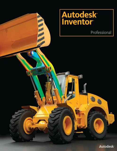
Shorten the roadto done.Autodesk®<strong>Inventor</strong>®Autodesk®<strong>Inventor</strong>ProfessionalRouted Systems
Experience your design before it’s built.The Autodesk ® <strong>Inventor</strong> ® product line provides acomprehensive and flexible set of software for 3Dmechanical design, simulation, tooling creation, and designcommunication that help you cost-effectively take advantageof a Digital Prototyping workflow to design and build betterproducts in less time.ContentsProduct SimulationSimulation ................................................. 4Routed Systems DesignTube and Pipe Design .............................. 7Cable and Harness Design ..................... 9Tooling CreationTooling and Mold Design ....................... 113D Mechanical DesignLayout and System Design ................... 14Plastic Part Design.................................. 15Sheet Metal Design ............................... 17Assembly Design .................................... 19CAD Productivity ToolsAutoCAD Integration and DWGInteroperability ....................................... 21Native Translators .................................. 23Learning Resources................................ 24Customization and Automation........... 25Design CommunicationDesign and ManufacturingDocumentation....................................... 263D Visualization and DesignCommunication ..................................... 28Data Management................................. 30Autodesk ® <strong>Inventor</strong> ® software is the foundation ofthe Autodesk solution for Digital Prototyping. The<strong>Inventor</strong> model is an accurate 3D digital prototypethat enables you to validate the form, fit, andfunction of a design as you work, minimizing theneed to test the design with physical prototypes.By enabling you to use a digital prototype todesign, visualize, and simulate your productsdigitally, <strong>Inventor</strong> software helps you communicatemore effectively, reduce errors, and deliver moreinnovative product designs faster.Design and Validate Your Products DigitallyAutodesk <strong>Inventor</strong> software products includean intuitive parametric design environment fordeveloping initial concept sketches and kinematicmodels of parts and assemblies. <strong>Inventor</strong> softwareautomates the advanced geometry creation ofintelligent components, such as plastic parts, steelframes, rotating machinery, tube and pipe runs,and electrical cable and wire harnesses. <strong>Inventor</strong>software helps reduce the geometry burden soyou can rapidly build and refine digital prototypesthat validate design functions and help minimizemanufacturing costs.Traditionally, validating the operating characteristicsof a design before it was built usually meant hiringexpensive specialists. But with <strong>Inventor</strong> software,you don’t need to be a simulation expert toeffectively simulate and optimize designs digitally.The <strong>Inventor</strong> product line includes easy-to-use andtightly integrated part and assembly-level motionsimulation and stress analysis functionality. Bysimulating stress, deflection, and motion, you canoptimize and validate your design under real-worldconditions, before the product or part is ever built.Learn how Autodesk<strong>Inventor</strong> can help youuse a digital prototype tobring better products tomarket faster and at lesscost.2
Streamline Mold DesignThe Autodesk <strong>Inventor</strong> product line includesautomated mold design tools that work directlyfrom <strong>Inventor</strong> 3D models of plastic parts. Poweredby Autodesk ® Moldflow ® plastic flow analysistools, <strong>Inventor</strong> can help to optimize your designfor moldability and minimize the number of molditerations.Improve Design Communication andCollaborationReduce errors and associated engineering changeorders before manufacturing by generatingmanufacturing documentation directly from yourvalidated 3D digital prototype. <strong>Inventor</strong> offers rapidand accurate output of production-ready drawingsdirectly from the 3D model. <strong>Inventor</strong> productbundles also include AutoCAD ® Mechanical softwarefor situations that require a high-productivity2D mechanical drafting tool.<strong>Inventor</strong> is tightly integrated with Autodesk datamanagement applications, enabling the efficient andsecure exchange of design data and promoting earliercollaboration between design and manufacturingworkgroups. Different workgroups can manageand track all components of a digital prototype withfree* Autodesk ® Design Review software—the alldigitalway to review, measure, mark up, and trackchanges to designs—allowing for better reuse ofcrucial design data, management of bills of materials(BOMs), and collaboration with other teams andpartners.With different product configurations that offerspecific levels of functionality to fit your designneeds, no company is more focused than Autodeskon helping you create accurate digital prototypesand bring better products to market faster at lesscost.AutoCAD Users:Move beyond 3D toDigital Prototyping.With Autodesk <strong>Inventor</strong>software, you can easilyintegrate AutoCAD ®and 3D data into a singledigital model to create avirtual representation ofthe final product.<strong>Inventor</strong> software helpsyou realize the benefitsof Digital Prototyping byproviding direct read andwrite of native DWG files, so there’s no risk ofinaccurate translations.Leveraging valuableDWG data with Autodesk<strong>Inventor</strong> software canhelp you compete moreeffectively, service yourclients better, and domore in-house.3
SimulationEasy-to-use and tightly integrated motion simulation andstress analysis in the Autodesk ® <strong>Inventor</strong> ® Professionalsoftware help you predict how the design will work under realworldconditions before building it.A comprehensivesimulation environmentprovides support formotion simulation andstatic and modal finiteelement analysis (FEA)at both the part andassembly level. Resultsfrom dynamic simulationallow engineers to useFEA more effectively byleveraging the reactionforces to set up theconditions for finiteelement stress analysis.Integrated Motion SimulationUse motion simulation—not intuition—to enhanceyour design decisions. The motion simulation featurein Autodesk <strong>Inventor</strong> software uses the assemblyconstraints in your 3D model to identify relevantrigid bodies, generate correct motion joints, andcompute dynamic behavior. This helps you to quicklyunderstand the design’s behaviors, including theposition, velocity, and accelerations of the movingparts.Integrated FEAIncrease the accuracy and reliability of your designstress analysis. Use integrated FEA to predict stressand deflection with accurate peak loads by transferringreaction forces from simulation time steps to AIP stressanalysis.Adaptive SolverConduct finite element studies faster and apply the resultssooner. Adaptive solver technology and localizedtuning algorithms within <strong>Inventor</strong> give you accurateresults more quickly.Static AnalysisMake sure your designs are strong enough whileavoiding over-designing. Examine the deformation ofparts and assemblies under static loads to determinemaximum and minimum stresses and deflections. Atthe same time, you can help assure designs meet thenecessary safety standards.Load DefinitionApply different driving loads and torques as well astime-based force functions using the Load Profileeditor. Use this tool to investigate the design’s performanceunder a range of different load conditions.4
SimulationOptimize and validate product performance before theproduct is built. Because these tools are part of the 3D designsoftware, it’s practical and cost-effective to employ simulationthroughout the design process.Modal AnalysisPrevent annoying and potentially hazardous vibrationswithout having to build and test physicalprototypes. Use studies of oscillating modes toexplore the vibrations and natural frequencies of theparts or assemblies within your design. Then makechanges that reduce the amplitude of oscillations.Parametric StudiesImprove the structural performance of your designs.Use the Parameter Table tool to create parametricstudies of design constraints and understand theeffect of different parameter values. You’ll be ableto explore the impact of changes, such as wall thickness,fillet radius, and hole diameter, to your design.Design UpdateQuickly apply the results of simulation studies toyour 3D model. You can select new parameter valuesfrom parametric and optimization studies. ThePromote tool automatically modifies the assembliesand parts within your model.Point TraceEasily calculate motion paths and save time bysimplifying the design of cams, grooved paths, andother motion-dependent components. Select anypoint in the model and use the Trace tool to displaythe point’s location at each step in the motion simulation.Using <strong>Inventor</strong>, you can also save simulationoutputs, including path traces and assembly positions,for use in part and assembly design.Optimization StudiesFind the best design solution without having to investigatean excessive number of options. When youconduct optimization studies, <strong>Inventor</strong> automaticallyseeks parameter values that meet your designcriteria.FEA Environment DefinitionSpend more time analyzing performance and lesstime preparing the analysis. <strong>Inventor</strong> gives you fullcontrol over materials, loads, constraints, contacts,mesh, solution quality, representations, andcomponent visibility. Automatic and manual contactdefinition and support for multiple simulations alsoprovide you with definition control.5
SimulationAutodesk <strong>Inventor</strong> Professional gives you the tools torecord your engineering decisions and share the resultsof simulation with team members - allowing you toderive maximum benefit from your digital prototypes.Model SimplificationReduce the time required to generate results fromstress analysis by simplifying part geometry to suppressfeatures during FEA.GraphingUse the comprehensive graphing capability in <strong>Inventor</strong>to quickly investigate how the dynamic characteristicsof your design vary through its operatingcycle. Plot physical parameters—such as position,force, and acceleration—versus time. Comparedifferent properties at each point in the simulationcycle, using multiple plots on the same graph.VisualizationInterpret the behavior and performance of your designmore fully. Watch as <strong>Inventor</strong> software providesanimated visualizations of your 3D model. Theseaccurate visualizations are based on the underlyingphysics models and load conditions applied to thedesign.Analysis OutputSelect different ways to view analysis results tomake it easier to understand and visualize complexproblems. Your analysis visualization optionsinclude smooth and contour color plots, mesh plots,animation, and interactive probes. You can focuson specific components of the design by selectingother components and hiding them from view.Report GenerationEasily share and record the results of your analysis.<strong>Inventor</strong> includes a custom report generator withembedded graphics.Microsoft Excel OutputExport XY plot data to Microsoft ® Excel ® worksheetsto analyze simulations and incorporateresults in presentations and reports.6
Tube and Pipe DesignUse Autodesk <strong>Inventor</strong> Professional to accelerate thedesign for routed elements, including tubing, piping, andflexible hose.Changing to differentstyles of fittings is quickand easy. Simply selecta different pipe styleand Autodesk <strong>Inventor</strong>repopulates the pipe runwith the new fittings whileadhering to any new designrules.Functional Route DesignSimplify the design of pipe runs—or spools—to fit incomplex assemblies or tight spaces. Automaticallyrouted segments respect predefined routing stylesto present you with alternative pipe routes thatcomply with routing rules, such as minimum ormaximum length criteria and bend radius. You canalso define pipe runs manually by creating 3D sketchgeometry or build them up interactively using theroute edit tools. For maximum control, combineautomatically routed segments with user-definedsegments.Pipe Fittings LibraryImprove quality, easily organize parts, and eliminatetedious searching with automatic placement ofthe correct part from an extensive library of pipingcomponents. The library contains commonly used,industry-standard tubing, piping, hose, and fittings,including ANSI, DIN, ISO, and JIS. Add or modifyproperties, including part numbers, to existing partsand control file names used to instance fittings,pipes, tubes, and other content.Flexible HoseMake sure flexible hose and fittings fit properlyusing a 3D digital prototype that drives accuratemanufacturing documentation. The system insertsappropriate hose fittings from the Content Centerand checks for minimum bend radius based on thehose style you select. Hose lengths are updatedautomatically for use in Length Roll-Up commands.7
Tube and Pipe DesignAutodesk <strong>Inventor</strong> Professional provides rules-basedrouting tools that select the correct fittings and helpsthe pipe run to comply with your standards for segmentlength, round-off increments, and bend radius.Rigid Tube RoutingQuickly create rigid tubes with superior control overthe shape, bend angles, and radii. Create rigid tubeswith an arbitrary number of bends and variablecustom bend angles and radii. The radius and rotationhandles offer greater control over the shape ofrigid tubes.Tube and Pipe StylesIncrease the quality and manufacturability ofdesigns by helping to ensure that tube and pipe runsautomatically adhere to preset design standards.Create tube and pipe styles to support the use ofthreaded, welded, and flanged connections. Stylesdefine the fittings to be used for both automatic andmanual routing, and enforce design rules, includingminimum segment lengths and minimum bend radii,as well as the maximum length between couplings.Creating RunsAutomatically populate piping routes with realparts that adhere to manufacturing standards. ThePopulate Route tool turns tube, pipe, and hoseroutes into physical pipe runs, automatically placingfittings, pipe segments, rigid tubes, and hoses asneeded. Standard <strong>Inventor</strong> parts are created duringthis process to make it easy to perform massproperty calculations and interference checks. Inaddition, couplings are automatically placed whenpipes reach their maximum length, and users canspecify length cutoff increments.Hygienic Pipe RunsDesign process lines that comply with sterility andhygiene standards required for process equipmentin the pharmaceutical, food, and personal care industries.Incorporate the correct slope into the piperoute, including use of drainable angle fittings thatcomply with the American Society of MechanicalEngineers (ASME) bioprocessing equipment whereneeded.Tube and Pipe DocumentationCreate manufacturing deliverables withoutredrawing—reducing errors and associated costs.Fully associative documentation for tube and piperuns provides assembly drawings that update whenevera change is made to the 3d design. ISOGENPCF file output creates isometric piping drawings inthird-party ISOGEN software such as Alias ISOGEN,and tubing bend tables in ASCII format provide theinformation required by tube bending machines.8
Cable and Harness DesignAutodesk <strong>Inventor</strong> Professional streamlines cable andharness design by leveraging wire list information importedfrom schematic design packages such as AutoCAD ®Electrical.Incorporating cable andharness runs into yourdigital prototypes savestime and money byallowing you to calculateaccurate path lengths,avoid small radius bends,and help electricalcomponents fit into themechanical assemblybefore manufacturing.Functional Harness DesignDesign cable and harness components in 3D toreduce manufacturing problems, facilitate outputof manufacturing drawings, and avoid late-stageengineering change orders. In <strong>Inventor</strong> software,wire list and connector information drives harnessdesign with built-in cross-checking of electrical andmechanical data. This allows you to make sure thatall wires and connectors in the wire list are representedin the 3D cable design.Wire List InputMaintain electrical design intent and reduce errorswhen importing wire lists into the assembly. Quicklyimport large wire lists from AutoCAD ® Electrical orthird-party schematic design applications, with detectionand correction of missing connectors, pins,and wire definitions.Wire RoutingQuickly route thousands of wires while exertingcontrol over the paths of critical wires. <strong>Inventor</strong>supports manual, interactive, and automatic routingwith accurate wire length calculation. Manualrouting requires the explicit selection of the wire’spath. Interactive routing requires selection of thestart/end points, after which the system algorithmchooses the shortest path. In automatic routing, thesystem finds the shortest possible path based on allavailable paths.Harness Path DefinitionOptimize the design of cable and harness assembliesto help proper spacing for manufacturing andto reduce errors in manufacturing caused by incompleteproduct definition. Define harness and cablepaths using a point-and-click methodology thatcreates 3D virtual conduits (segments) in the model.Create associative relationships that will update theharness whenever you change a design component.Add points or move existing points to refine theoverall shape of the harness.9
Cable and Harness DesignFull integration with the bill of materials (BOM) tools inAutodesk <strong>Inventor</strong> helps you make sure that your BOMaccurately represents the electrical components in yourdesign.Ribbon CablesReduce errors in the design of electronic equipmentby incorporating ribbon cables in your 3D digital prototype.Add ribbon cables between connectors withfull control over the locations of twists and folds.Harness ValidationImprove cable quality and manufacturability andprevent costly recalls and product failures by adheringto design standards. <strong>Inventor</strong> software automaticallycalculates quality parameters, including bundlediameter, bend radius, and wire lengths wheneveryou make changes to the harness. This allows you toeliminate the time-consuming, error-prone process ofmanually measuring a hardware prototype.Harness DocumentationQuickly and easily create manufacturing documentationbefore you build the first article. Since cableand harness geometry is native to <strong>Inventor</strong>, you cancreate assembly documentation showing accuratecable and harness placement details. You’ll be ableto:Connector AuthoringSet up company-specific connector libraries toencourage the use of preferred connectors in thedesign of electrical products. <strong>Inventor</strong> softwareincludes an extensive library of connectors to simplifyselection and placement. The Content Centerprovides an easy-to-use editor to add user-definedconnectors, and add or modify properties, such aspart numbers and default file names, used wheninstancing connectors.• Automatic create and update 3D nailboard diagramsfor 3D wire harnesses, cables, and ribboncables• Run reports such as wire run lists, terminationcharts, cut tables, and other documentationneeded for the design and manufacture of harnesses• Output XML files to transfer the final wire connectivityinformation and streamline the creation ofschematics and wiring diagrams, using AutoCADElectrical or other schematic design software10
Tooling And Mold DesignAutodesk <strong>Inventor</strong> Professional helps automate key aspects ofthe design of injection molds for plastic parts. This allows youto quickly create and validate complete mold designs, reducingerrors and improving mold performance.With its intuitive molddesign workflow,<strong>Inventor</strong> software guidesyou through the molddesign process in a waythat is natural for theexperienced user, while atthe same time supportivefor the novice.Streamline the design of plastic injection moldsAutodesk <strong>Inventor</strong> software includes easy-tousemold design features that work directlyfrom <strong>Inventor</strong> 3D models of plastic parts. Fullassociativity to the <strong>Inventor</strong> digital model helpsmake sure that any changes to the model areautomatically reflected in the mold design. <strong>Inventor</strong>guides you through the mold design process andautomates a number of complex operations, suchas capping openings and runoff/shutoff surfacegeneration. The result is higher quality products andfaster time to market.Part PreparationGain access to extensive material propertyinformation by selecting part material from theAutodesk ® Moldflow ® material database, theworld’s largest material database for injectionplastic molding. Interactively define the partingdirection. A default work piece size is recommendedby the system based on the part dimensions. Youcan also easily edit the settings, if necessary. Anyinformation added to the part model is reused in themold design process.PartCore/CavityPatch and Parting Surface CreationAccelerate mold design by creating surfacesautomatically. Close multiple openings in your partmodel using automated patch surface creation. Andgenerate parting surfaces automatically based onthe defined parting direction.Intelligent PatchingAutomated Core and Cavity DesignCore and cavity design is time consuming with traditionalCAD tools, but the mold design knowledgein <strong>Inventor</strong> software saves you time and reducesrework. With <strong>Inventor</strong>, you can split the work pieceto generate the core and cavity halves based on theparting surface definition. Create side core designsto match the mold assembly, and incorporate oldside core designs into existing mold assemblies. Formulticavity mold designs, easily define the moldconfiguration layout as circular, rectangular, orvariable. And use automated core and cavity designtools to create family molds.11
Tooling And Mold DesignAutodesk <strong>Inventor</strong> Professional includes Moldflow plastic flowanalysis tools. Use them to determine material flow rates, idealgate locations, shrinkage, and process parameters.Runner and Gate DesignReduce mold design lead time with automatedrunner and gate design tools. Facilitate theefficient distribution of molten plastic from themachine nozzle to the mold cavities by designingthe complete runner system, including the sprue,runners, and gates. Gate location analysis toolshelp you determine gate locations accurately andefficiently. Preconfigured shapes allow you toquickly create gate points, gates, runners, sprues,and cold wells.Cooling Channel DesignReduce the time it takes to add cooling channelsto the mold base while avoiding errors andinconsistencies. With <strong>Inventor</strong> Mold Design, youcan quickly design cooling channels for the moldbase through an intuitive user interface. Enforceconsistency and reduce mistakes by selectingcooling components, such as connectors and pipeplugs, sealing plugs, and O-rings, from a standardcatalog.Moldability AnalysisAvoid costly mistakes by detecting moldabilityissues early in the design cycle. With <strong>Inventor</strong>software, you can analyze the part model beforestarting the mold design process. You quicklyenhance your understanding of the plastic filling,sink marks, cooling efficiency, gate location, andoptimum molding window.12
Tooling And Mold DesignAutodesk <strong>Inventor</strong> Professional provides an extensive collectionof vendor catalogs of standard mold bases and components soyou won’t have to spend time modeling them.Mold Base LibrariesReuse standard mold base components across theorganization, allowing you to avoid duplicate workwhile taking advantage of proven design knowledge.<strong>Inventor</strong> software supports a wide range of moldbase catalogs, including DME, Futaba, HASCO,LKM, Pedrotti, Polimold, Rabourdin, and Strack.A single database stores and delivers easy accessto standard components. When required, you canefficiently customize standard mold bases to suityour needs.Standard Mold Base PartsImprove productivity and avoid errors by reusingexisting mold design knowledge as you create thedetailed mold design in 3D. Begin by selecting moldbase components from standard catalogs, includingMeusburger, Misumi, National, Progressive, Punch,and Sideco. Design or modify standard components,such as sliders, lifters, ejectors, sprue bushings, andlocating rings. When you have standard mold basecomponents that meet your needs, you can exportthem as templates for future use.DocumentationReduce mold design lead time by generatingdrawings and BOMs automatically. <strong>Inventor</strong> allowsyou to automatically create 2D drawings of molddesigns and related BOMs for use in documentationor manufacturing. When you make changes to the3D design model, <strong>Inventor</strong> automatically updatesthe drawings and BOMs.13
3D Layout and System DesignGetting the initial design concept right is the key to asuccessful project. Move your initial design studies from paperby using the parametric design environment in <strong>Inventor</strong> todevelop initial concept sketches and kinematic models.With dynamic sketchblocks, you can quicklyevaluate different conceptsand then convert yoursketches into a fullyconstrained 3D assemblymodel to form a digitalprototype. The DesignAccelerators in <strong>Inventor</strong>software provides thefastest way to add theremaining components,such as drive mechanisms,fasteners, steel frames, andhydraulic systems.SketchingEvaluate different design ideas before creatingdetailed part and assembly models. Using the<strong>Inventor</strong> sketch environment, you can quicklycapture design ideas as versatile 2D layouts.Combining the power of constraints with easyto-usetools for modifying sketches lets you trydifferent design concepts and control color and linestyle, allowing you to find the best way to conveyyour design ideas.Layout DesignPerform detailed motion studies using sketches,and find kinematic solutions in the conceptphase. Quickly evaluate different mechanisms bycombining sketch blocks representing individualrigid and moving bodies to create 2D kinematicmodels. With a working design, you use the samesketch blocks to populate the assembly withcorrectly constrained part models.Design AcceleratorsRapidly design, analyze, and create commonly usedmachine components based on functional requirementsand specifications. Move beyond 2D draftingand 3D modeling and accelerate design by workingwith parts that are based on mechanical relationshipsrather than on geometric descriptions (lines,arcs, and circles) and constraints. Design acceleratorscreate parts and assemblies based on user inputof real-world attributes and conditions. <strong>Inventor</strong>includes component generators for mechanical connections,shafts and hubs, O-rings, gear design, beltand chain drives, power screws, and springs.14
Plastic Part DesignFunctional plastic features, rule-based fillets and powerfulmulti-body workflows simplify the design of high-qualitymolded part models.Molded Part DefinitionMake sure molded parts meet aesthetic guidelinesfor the position of parting lines while supportingcost-effective manufacturing requirements. Dividethe 3D component to define the molded parts, usingtools to identify silhouette curves for optimumparting plane geometry and multibody operationsthat make it easy to split the part into separatebodies.Rule FilletsSpeed up the creation of fillets on machined andmolded parts, and make changes to parts withouthaving to recreate the fillets. Rule fillets generatefillet geometry based on functional rules youestablish. Support for multiple rules per featurelets you define complex fillet operations with asingle feature, greatly reducing the need to selectindividual edges.Technical Plastic FeaturesQuickly add the technical plastic features thatdefine manufacturing-ready parts. With built-insupport for pull direction and draft angle, <strong>Inventor</strong>plastic features generate multiple-element featuresfor molded plastic parts in a single step. Addgrills, bosses, lips, rests, and snap-fit fittings toplastic parts with less modeling than traditionalapproaches.Draft Angle and Cross-Section AnalysisCross-section analysis displays wall thickness,color-coded feedback of minimum and maximumthickness violations, and moment of inertia atthe end of the cross section. Draft angle analysisdisplays color-coded draft angle based on a pulldirection, which can be defined by an axis, plane, orplanar face.16
Sheet Metal DesignUse the <strong>Inventor</strong> Digital Prototype to simplify the designof complex sheet metal parts.Autodesk <strong>Inventor</strong>software improves yourproductivity when youdesign sheet metal partsby providing a digitalprototype that combinesmanufacturing information– such as punch toolparameters and custombend tables – with anaccurate, 3D model ofsheet metal folding anda flat-pattern editingenvironment wheremanufacturing engineerscan tweak flat patterns tominimize manufacturingcosts.Sheet Metal StylesGenerate flat patterns that accurately reflect yourmanufacturing capabilities. Control sheet metalunfolding with styles that define the materialthickness, bend rules, and corner reliefs. To controlthe unfolding geometry, <strong>Inventor</strong> software supportslinear unfolding, custom unfold equations, andcustom bend tables.Sheet Metal FlangesSpeed up the design of sheet metal parts withcomplex flanges using intelligent 3D models thattake your manufacturing processes into account.Intelligent features enable the creation of multipleflanges in a single operation with rich unfold options,automatic mitering, and seam level overrides forprecise control of overlap and relief conditions.Supported features include flanges, contour flanges,and lofted flanges.Transitional ShapesEfficiently design parts for ducting, materialhandling hoppers, exhaust hoods, and other usesthat require press-brake or die-form techniques.The lofted flange and rip features simplify thedesign of transitional shapes with options tocreate geometry for both die-form operations andpress brakes.Unfold Design WorkflowsSimplify the inclusion of punches, cuts, fillets,chamfers, and extrusions that span sheetmetal bend plates. Use the unfold and refoldcommands to create features using an unfoldedrepresentation of the part. Automaticallypropagate the resulting features to both thefolded model and the flat pattern.Roll-Formed PartsCreate accurate digital prototypes that include rollformedparts. The contour roll command simplifiesthe creation of rolled features with full support forsupplemental sheet metal features and flat-patternoperations.17
Sheet Metal DesignFlat-Pattern ModificationOptimize flat patterns to eliminate unnecessarymanufacturing costs. Generate flat-pattern modelsautomatically from the folded 3D model. Thenmodify the model to define the optimum bendsequence, add cosmetic centerlines, define postformoperations, and modify corner reliefs to match yourshop-floor capabilities. Information defined in theflat pattern also simplifies the creation of accuratemanufacturing drawings.Sheet Metal FastenersQuickly insert specialized sheet metal fasteners intosheet metal designs. You’ll find a comprehensiverange of PEM fasteners in the Content Center.DXF OutputReduce programming time by eliminating effortspent cleaning up DXF files for CNC machining.DXF/DWG export for sheet metal provides controlof preprocessing and postprocessing options suchas DXF/DWG file version, layer mapping, userdefinedchord length for spline simplification, andcustomization through external XML files.Punch LibrariesStandardize punch usage and reduce computernumerical control (CNC) tooling costs by definingyour own sheet metal punch libraries. Table-drivenpunches let you define families of punches—typicallydifferent sizes of the same punch shape with fullrepresentation of manufacturing parameters,including punchID, punch depth, and sketches foralternative punch representations.Sheet Metal Manufacturing DrawingsQuickly create accurate manufacturing drawingsto support sheet metal manufacturing operations.Document flat-pattern drawings by inserting punchnotes, punch tables, and bend tables that displaypunch and bend data from your 3D model, andselect the display of bend directions using drawingstyles.18
Assembly DesignAutodesk <strong>Inventor</strong> software combines design acceleratorswith assembly tools so you can be sure that every part andcomponent in an assembly design fits correctly.<strong>Inventor</strong> provides thetools to control and managethe data created bylarge assembly designs,allowing you to work onjust the components requiredto complete a particularpart of the design.Assembly DesignQuickly assemble individual parts andsubassemblies to define the complete productstructure. Verify that your product can beassembled. Insert and position new componentsin the assembly, using constraints to capture thepositional relationships that define fixed and movingcomponents.Interference Analysis and Contact DetectionReduce costly errors and improve manufacturabilityby testing assembly function within <strong>Inventor</strong>. Checkfor static interference among parts with graphichighlighting of overlapping material, and then testfor potential collisions between moving parts bydriving assembly constraints or dragging componentsuntil they collide.Assembly ConfigurationsEasily design and document product families usingassembly configurations to define variations froma master assembly. Exclude or substitute individualcomponents and make changes to dimension andconstraint values. Document the whole part orassembly configuration using the Table tool, whichautomatically creates the parameter table in a 2Ddrawing.Large Assembly PerformanceRealize the benefits of 3D design when developingvery large assemblies. Native shrinkwrap gives youthe ability to manage large assemblies by convertingsub-assemblies into simplified part models orlightweight surface models. With level of detail(LOD) representations, you can switch between fulland lightweight representations to control memoryconsumption and increase performance. A largeassembly “capacity meter” shows you how muchmemory is available.19
Assembly DesignAccurately validate interference and mass properties toproduce quality products the first time.Frame GeneratorQuickly design and develop welded frames forindustrial machinery applications. Frame Generatorbuilds up structural frames by dropping predefinedsteel shapes onto wireframe or solid skeletal framesand simplifies creation of end conditions withpredefined options for mitered, notched, and straightbutt welded joints. It includes profile authoring soyou can add custom profiles to the existing library ofstandard profiles.Content CenterThe Content Center provides fast and easy accessto frequently used content, simplifying creation,reuse, and management of all standard companycontent. The Content Center is a centralized libraryfor engineering content that provides an easy-to-usecontent browser with Search and Filter tools to helpyou quickly find the right parts families. It includesmore than 650,000 components—such as nuts,bolts, and screws—and enables companies to add inhouseparts and standard features to user-definedlibraries.AutoLimitsReduce errors and engineering changes throughautomatic monitoring of critical design parameters.AutoLimits can be used to monitor length, distance,angle, diameter, loop length, area, volume, and mass.AutoLimits icons change color when the monitoredparameters exceed the prescribed parameter range.WeldmentsImprove quality and documentation of weldedassemblies. Define weld preparation, weld creation,and postweld operations with full 3D representationof fillet, gap, or groove welds that provide weldmentanalysis and bead volume reports. Automaticallycreate 3D annotation based on industry or companystandards and generate associative 2D weld symbolsfor documentation.Supplier Content CenterReduce the time and effort to incorporate standardcomponents into designs. The Supplier ContentCenter provides web-based access to componentmodels from more than 100 leading manufacturers.The simple-to-use browser provides quick and easyaccess to models in native <strong>Inventor</strong> format. And it’sfully integrated with the <strong>Inventor</strong> Content Center.Design Doctor Find and fix errors in a 3D model with a diagnostictool that identifies potential design issues andrecommends corrections.Assembly STL OutputQuickly create source stereolithography (STL) filesfor rapid prototyping of <strong>Inventor</strong> assemblies. Savefiles in the STL format directly from the <strong>Inventor</strong>assembly environment.20
AutoCAD Integration and DWG InteroperabilityAll Autodesk <strong>Inventor</strong> software products bundles also includethe latest version of AutoCAD Mechanical.DWG SaveIntegrate DWG technology into 3D designworkflows to:• Take advantage of existing skills• Easily combine parts, assembly, and schematicdrawings data• Streamline communication with suppliers andpartners who rely on DWG technologyDirect DWG OpenGain access to existing 2D design data withoutinstalling or learning AutoCAD software. OpenAutoCAD drawings directly in the <strong>Inventor</strong>application to view, plot, and measure using familiar<strong>Inventor</strong> commands. Incorporate existing 2D designdata into 3D design workflows using copy and pastetools.The DWG Save feature stores <strong>Inventor</strong> drawingviews in a DWG file to provide view, plot, andmeasure in AutoCAD with complete visual fidelity,while preserving fully associative drawing updates.AutoCAD Blocks from <strong>Inventor</strong> ViewsReduce the cost of using 3D to upgrade equipmentand machinery originally designed in 2D. Thisfeature generates AutoCAD blocks from <strong>Inventor</strong>drawing views, so you can redesign subassembliesusing <strong>Inventor</strong> and then integrate the new drawingviews directly into the original drawings.Template SynchronizationReduce the time required to create drawingsthat comply with customer or partner drawingstandards. Simply open a DWG file in <strong>Inventor</strong> andautomatically create layers and dimension andtext styles based on the AutoCAD styles in theDWG file thus reducing the time required to createdrawings that comply with your customers’ drawingstandards.22
Native TranslatorsAccept projects that use different applications. Autodesk<strong>Inventor</strong> offers a comprehensive suite of translators, includingnative translators that read and write files from other CADtools and translators for industry standard formats such asIGES and STEP.In today’s world ofintegrated supply chains,you may need to workwith 3rd-party CAD datafrom customers andsuppliers. Using thetranslators in <strong>Inventor</strong>,you can accept andsupply data in thecustomer’s preferredformat.Native TranslatorsStreamline projects that require opening filesfrom vendors or customers in native formats. Anddeliver 3D design data to customers or vendorswho prefer native file formats. You can easilyexchange data between <strong>Inventor</strong> and CATIA V5 ,UGS ® , SolidWorks ® , and Pro/ENGINEER ® . <strong>Inventor</strong>supports direct import and export of CATIA V5,JT 6, JT 7, Parasolid ® , and GRANITE files. It alsosupports direct import of UG-NX , SolidWorks,Pro/E, and SAT files.STEP/IGESEnable accurate collaboration with suppliers andcustomers by sharing and reusing design databetween 3D CAD/CAM systems. Read and writedesign and drawing data using industry-standardformats.Construction EnvironmentReduce the time you need to inspect and repaircustomer data files. The <strong>Inventor</strong> constructionenvironment provides fault-tolerant import of largeSTEP and IGES data sets. It can quarantine entitiescontaining geometric problems, such as surfaceslivers and mismatched boundary curves. Then usethe comprehensive toolkit for inspecting, editing,and correcting quarantined entities, including solids,surfaces, wireframes, and points. Data sets canbe corrected and promoted into 3D part models,surfaces, or 3D wireframes.AEC ExchangeThe architecture, engineering, and construction(AEC) exchange tool creates and publishessimplified 3D representations, intelligent connectionpoints, and additional information using theAutodesk Package Files format (.adsk ) to facilitateexchange of data with Autodesk ® REVIT ® MEP andAutodesk ® REVIT ® Architecture.23
Learning ResourcesAccelerate the adoption of Digital Prototyping. <strong>Inventor</strong>software offers a range of learning and reference resources tohelp you build and maintain your skills as well as quickly makethe most of the 3D design environment.Learn new tricks, lookup information about aprocedure or tool, and getthe latest tips you needto stay productive.Advanced Help SystemSpeed the transition to 3D with contextual help.The advanced help system is easier to use, withimproved navigation and profiles that present youwith information based on your user profile.Engineer’s HandbookSave time researching engineering formulas,tables, and standards. The Engineer’s Handbookprovides a comprehensive online reference ofengineering theory, formulas, and algorithms. Thismanufacturing knowledge base is easily accessiblefrom anywhere in the <strong>Inventor</strong> software.Deployment GuideQuicklyand easily complete your installation of<strong>Inventor</strong> software. Whether you are planninga new deployment or upgrading to Autodesk<strong>Inventor</strong> 2010, this easy-to-read guide providesthe information you need to successfully plan yourinstallation and rollout.Tutorials and Skill BuildersUse extended learning modules, including tutorialswith “show me” animations and skill builders, toenhance your understanding and skills.E-LearningAccelerate learning through flexible access totutorials and best practices. A valuable componentof the Autodesk ® Subscription program, e-Learningprovides a continually expanding curriculum ofshort training exercises.24
Customization and AutomationUsing the <strong>Inventor</strong> API (application programming interface),you can streamline frequently used procedures and automatespecialized workflows that support design standards andengineering processes.Increase speed andproductivity withconfigurable styles sodrawing conform tostandards, and publishcustom componentsin the Content Centerto make sure designersuse the appropriatecomponents in theirdesigns.Content Center Publishing ToolsQuickly prepare and publish intelligent part librariesfor internal use and parts catalogs. Publishing toolsinclude a Microsoft ® Excel editing environment andbatch processing for large data sets.Task SchedulerIncrease productivity by automating repetitive andnonproductive tasks. The <strong>Inventor</strong> Task Schedulerallows you to schedule single or multiple (batch)automated tasks, including DWF publishing, printing,file migration, IGES and STEP transfers, andAutodesk ® Vault operations. You can also check outand download files from the Vault.Open APIIncrease productivity by developing tools to automateyour company’s design and documentationprocesses. <strong>Inventor</strong> software includes a welldocumentedAPI to create customized programsthat automate specialized workflows and extend the<strong>Inventor</strong> data model with custom attributes.StylesWork faster by quickly changing the formattingof an entire document, without sacrificing alignmentto company standards. Styles are combinationsof formatting characteristics such as font, font size,color, standards, linetype, and material. Name yourpreferred styles and store them as templates thatcan control all aspects of drawing formats. Whenyou apply a style, all the formatting instructions inthat style are applied at one time, and you can configurea set of common styles for use by an entireproject team.25
Design and Manufacturing DocumentationEasily generate and share production-ready drawings withmanufacturing teams and outside suppliers. Autodesk<strong>Inventor</strong> software allows you to generate engineering andmanufacturing documentation from a validated digitalprototype to reduce errors and deliver designs in less time.Extending theadvantages of AutoCAD ®software, Autodesk<strong>Inventor</strong> softwaretakes the productionof manufacturingdocumentation to thenext level of productivitythrough automaticgeneration of drawingviews and comprehensivetools for finishing drawings.Automatic Drawing ViewsCreate drawings dramatically faster than with2D methods. You simply call out drawing views,including front, side, ISO, detail, section, andauxiliary views, and Autodesk <strong>Inventor</strong> projectsthe geometry. <strong>Inventor</strong> software also deliverscomprehensive options for controlling hidden linedisplay and support for technical drawing standardssuch as GB, JIS, BSI, ISO, DIN, ANSI, and ESKD.Timesaving options include:• Automatic retrieval of dimension data from the3D model, allowing you to place the dimensions,including isometric view dimensions, withautomatically updated dimension values.• The Arrange Dimensions command, which letsyou align and clean up retrieved dimensions toproduce quality production drawings in minutes.• A robust palette of dimension, annotation, and2D symbols for fast, flexible completion of thedrawing set.26
Design and Manufacturing DocumentationAutodesk <strong>Inventor</strong> software provides support for all majordrawing standards, automated drawing updates, and output inthe DWG format.Automatic Drawing UpdatesReduce errors and the need for manual updatechecks with automatic drawing updates. <strong>Inventor</strong>associates drawing views with the originalcomponents, so any change to a part or assembly isautomatically reflected in the drawing. <strong>Inventor</strong> alsosupports global updates of drawing resources suchas title blocks, borders, and sketched symbols.Associative Parts ListAutomatically generate and update accurate partslists in a fraction of the time required by traditional2D methods, virtually eliminating the risk ofhuman error. The associative parts list enablesyou to maintain an accurate parts list, with partsand subassembly quantities that are automaticallykept up to date, organized, and populated into adrawing parts list. The associative parts allow you torapidly add ballons and item numbers to assemblydrawings. You also have greater flexibility incustomizing parts lists to meet company standards.Bill of MaterialsProvide earlier visibility into accurate componentlists to improve costing and sourcing decisions.Simplify release to manufacturing with accurateengineering bill of materials (BOM) data. TheBOM is a single source for managing the assemblyand subassembly structure of purchased andnonpurchased parts, including virtual components.Timesaving features include:• Automatically number items, with support fornumeric and alpha characters and item numberoverride.• Define materials for virtual components such asglue and paint.• Directly edit materials in the BOM table, whichallows material changes to be made to more thanone item at the same time.27
3D Visualization and Design CommunicationImprove communication and collaboration with stakeholdersand customers using the same digital prototype used todesign and validate their designs.People withoutengineering experiencetypically do not understandengineering drawings. Theyprefer images that helpthem visualize a design.With the power of moderndesktop computers andthe advanced renderingfeatures included withAutodesk <strong>Inventor</strong>software, it’s easy to createpowerful images andvideos that help sell yourideas.Autodesk <strong>Inventor</strong> StudioHelp eliminate the high costs of prototyping andproduct photography with high-quality, photorealisticrenderings and animations. Autodesk ® <strong>Inventor</strong>® Studio provides the state-of-the-art tools thatdesign engineers need to quickly create renderingsand animations.Publishing FormatsShare product information with partners and customerswho need to incorporate your designs intotheir products. Users can publish <strong>Inventor</strong> drawingsas PDF files, publish 3D part and assembly modelsin SAT or JT formats, and create stereolithography(STL) files for output to STL and 3D print machines.28
3D Visualization and Design CommunicationDesigners and engineers now have the tools to convey designideas to managers in a compelling way, explain designs tomanufacturing, and convince customers that they have thebest solution for their needs.Technical IllustrationsUse the Presentation Environment in <strong>Inventor</strong>software to quickly create technical illustrations,process sheets, training materials, parts manuals,assembly instruction sheets, and videos to train assemblyteams on the manufacturing floor.DWF PublishingImprove product quality, decrease time to market,and reduce scrap and rework costs by using DWF technology to streamline communication with suppliers,purchasing, and other supply chain partners.You can easily publish information required bymanufacturing partners, including assembly animations,detailed step-by-step assembly instructions,2D drawings, and 3D models with BOM information.DWF MarkupEasily track, manage, and verify multiple markupsand design changes throughout the design reviewprocess. Overlay DWF markups directly onto Autodesk<strong>Inventor</strong> drawings, provide status, and makechanges. You can then republish or round-trip thosechanges back to the design reviewer to completethe process.29
Data ManagementUse Autodesk <strong>Inventor</strong> software to efficiently and securelyexchange design data and support collaboration betweendifferent engineering contributors, including industrial design,product design, and manufacturing.Autodesk DataManagement solutionsallows design workgroupsto manage and track allthe design componentsof a digital prototype,helping them to betterreuse critical designdata, manage BOMs,and promote earliercollaboration withmanufacturing teams andclients.Autodesk Vault Software IntegrationMaximize returns on your investment in designdata by maximizing design reuse with Autodesk ®Vault software. A centralized data managementapplication in <strong>Inventor</strong>, Autodesk Vault allowsworkgroups to securely store and manage designdata and related documents. Vault manages inprogressdesigns while making it easier to find,reference, and reuse design dataAutodesk Vault ManufacturingAutodesk ® Vault Manufacturing software (soldseparately and previously known as Autodesk ®Productstream ® ) securely stores and managesengineering information, design data, anddocuments, enabling you to shorten the design-tomanufacturingprocess. It helps design, engineering,and manufacturing departments across separatelocations collaborate and share Digital Prototypinginformation. It also gives your design departmentsadvanced tools to track engineering change orders,manage BOMs, and promote earlier collaborationthrough integration with manufacturing businesssystems. With support for multi-CAD environments,Vault allows you to share and manage designs andengineering data created with third-party softwareand AutoCAD software throughout the productlifecycle.30
Learn MoreLearn about the different <strong>Inventor</strong> products available tofit your specific design needs, and discover why <strong>Inventor</strong>products are the best choice for manufacturing companies.For more information, visit www.autodesk.com/inventor.AutoCAD <strong>Inventor</strong>Suite 2010AutoCAD <strong>Inventor</strong>Routed Systems Suite2010AutoCAD <strong>Inventor</strong>Simulation Suite 2010AutoCAD <strong>Inventor</strong>Tooling Suite 2010AutoCAD <strong>Inventor</strong>Professional Suite 2010Autodesk <strong>Inventor</strong> • • • • •AutoCAD Mechanical • • • • •Autodesk Vault • • • • •Cable and HarnessDesign • •Tube, Pipe, and FlexibleHose Design • •Stress Analysis (FEA) • •Dynamic Simulation • •Tooling and MoldDesign • •3131
Digital Heading Prototyping large > for KievitPro the Manufacturing Regular Market 23 on 23 pt, 75%Autodeskblack. Utisenima world-leadingad minisuppliermim veniamiof engineeringquissoftware,nostrudproviding exercitation companies ullam, with corpor tools to suscipit experience laboris their ideas Lorembefore ipsum they etalus are real. siti By amet, putting duis powerful autem Digital conitu Prototyping secuturtechnology adipscing within elitsef the diam reach eiusmod of mainstream magnus. manufacturers, EtionAutodesk is changing the way manufacturers think about theirdesign ullam, processes corpor and suscipit is helping laboris them Lorem create more ipsum productive etalusworkflows. siti amet, The duis Autodesk autem approach conitu to secutur Digital Prototyping adipscing isunique elitsef in diam that it eiusmod is scalable, magnus. attainable, and cost-effective, whichallows a broader group of manufacturers to realize the benefitswith minimal disruption to existing workflows, and provides themost straightforward path to creating and maintaining a singledigital model in a multidisciplinary engineering environment.Learn More or PurchaseAccess specialists worldwide who can provide product expertise, a deepunderstanding of your industry, and value that extends beyond your softwarepurchase. To purchase Autodesk ® <strong>Inventor</strong> ® software contact an AutodeskPremier Solutions Provider or Autodesk Authorized Reseller. Locate a resellernear you at www.autodesk.com/reseller.Autodesk Learning and EducationFrom instructor-led or self-paced classes to online training or educationresources, Autodesk offers learning solutions to fit your needs. Get expertguidance at an Autodesk Authorized Training Center (ATC ® ) site, access learningtools online or at your local bookstore, and validate your experience withAutodesk certifications. Learn more at www.autodesk.com/learning.AutodeskText headingServices> KievitProand SupportBold 8.5 on 10.5 pt, product family colorAccelerateBody Text >returnKievitProon investmentRegular 8.5andon 10.5optimizept, black.productivitylorem ipsumwithetalusinnovativesit amet,purchaseduis autemmethods,consecuturcompanionadipscingproducts,elit, sef diamconsultingnonumyservices,eiusmodandtemporsupportincidentfromAutodeskut labore magnaand Autodeskaliquamauthorizederat volupat.partners.Ut enimDesignedad minimimto getveniamiyou upquisto speedandnostrudkeepexercitationyou ahead ofullam,the competition,corpor suscipittheselaboristoolsnisihelputyoualiquipmakeextheea commodomostofconseauat.your softwareDuis autempurchase—novel eummatterirure etaluswhatinindustryreprehjenderityou are in.in volupateLearn morevelitatwww.autodesk.com/servicesandsupport.ewsse moestai xom consequat.AutodeskText headingSubscriptionGetBodytheText.benefitsVel illumof increasedetalusim euproductivity,fugiat nullapredictablepariartur —ignissimbudgeting,quiandblanditsimplifiedlicensepraes entlmanagementupatum delenitwith Autodeskaigue duos ® Subscription.etalus et molestaisYou getexcepturisioany new upgradestoccaecetofcupidatyour Autodesknon. Loremsoftwareipsum etalusand anysitincrementalamet, duis autemproductconsecuturenhancements,adipscingifelit,thesesef diamarenonumyreleasedeiusmodduring yourte mporSubscriptionincidentterm.ut laboreIn addition,magna aliquamyou geterat.exclusivelicense terms available only to Subscription members. A range of communityresources,Text headingincluding web support direct from Autodesk technical experts,self-pacedBody text.training,Lorem ipsumand e-Learning,etalus sit amet,helpduisextendautemyourconsecuturskills and makeadipscingAutodeskelit,Subscriptionsef diam nonumythe besteiusmodway totemporoptimizeincidentyour investment.ut labore magnaLearnaliquammore ateratwww.autodesk.com/subscription.volupat. Ut enim ad minimim veniami quis nostrud exercitation ullam, corporsuscipit *Free products laboris are subject nisi ut to the aliquip terms and ex conditions ea commodo of the end-user conseauat. license agreement Duis autem that accompanies vel eumirure download etalus of the in software. reprehjenderit.Image courtesy of Engineering Center LTD, RussiaAutodesk, AutoCAD, AliasStudio, Autodesk <strong>Inventor</strong>, Design Doctor, DWF, DWG, DXF, <strong>Inventor</strong>, Productstream,and Revit are registered trademarks or trademarks of Autodesk, Inc., and/or its subsidiaries and/or affiliates inthe USA and/or other countries. All other brand names, product names, or trademarks belong to their respectiveLegal holders. text Autodesk > KievitPro reserves Regular the 6 right on 8 pt, to alter black product — Registered offerings trademarks and specifications of Autodesk, at any Inc., time in the without USA notice, andand/or is not responsible other countries. for typographical All other product or graphical names, errors brand that names, may or appear trademarks in this document. belong to their respectiveholders. © 2009 Autodesk, © 2008 Autodesk, Inc. All rights Inc. All reserved. rights reserved. 462A1-000000-MZ01part number


