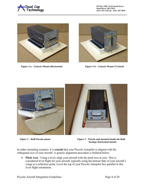
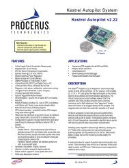
<strong>Cloud</strong> <strong>Cap</strong><strong>Technology</strong>PO Box 1500, No 8 Fourth StreetHood River, OR 97031(541) 387-2120 ph (541) 387-2030faxFigure 1-a – Generic Mount (Horizontal)Figure 1-b – Generic Mount (Vertical)Figure 2 – RnR Piccolo mountFigure 3 – Piccolo unit mounted inside the RnRfuselage (horizontal mount)In either mounting scenario, it is crucial that your Piccolo Autopilot is aligned with theorthogonal axis of your aircraft. A generic alignment procedure is bulleted below.• Pitch Axis - Using a level, align your aircraft with the pitch axis at zero. This isconsidered level flight for your aircraft, typically using the bottom flats of your aircraft’swings as a reference point. Level the top of your Piccolo Autopilot box parallel to thislevel flight orientation.Piccolo <strong>Aircraft</strong> Integration Guidelines Page 4 of 20
<strong>Cloud</strong> <strong>Cap</strong><strong>Technology</strong>PO Box 1500, No 8 Fourth StreetHood River, OR 97031(541) 387-2120 ph (541) 387-2030fax• Roll Axis – Using the level on top of the wings, position your aircraft at level flight withthe roll axis. Now align the Piccolo Autopilot in parallel with this zero degree roll axis(perpendicular to direction of flight).• Yaw Axis – Finding the zero point in the yaw axis is usually the most difficult, unlessyour aircraft has flat sides (parallel to direction of flight) , in which you could turn theaircraft on its side, and define the zero degree yaw using a level. The next best way, is toscribe a line on the center of your mount or the Piccolo Autopilot, parallel to the sides ofthe Piccolo Autopilot box. Align it with the center of your aircraft in the direction offlight, by taking measurement off the insides of your aircraft’s fuselage. If your PiccoloAutopilot is visible through a hatch, always check your placement by standing behind theaircraft’s tail, and visually seeing the scribed line with the alignment of your aircraft.There are multiple ways to engineer a proper mount, and no single method is best for allapplications. Outlined above are two relatively simple methods which meet the generalrequirements, and should help guide you in your Piccoloinstallation.If soft mounting the avionics is not viable, or you arecarrying other vibration sensitive payloads, such as avideo camera with zoom, a third option to consider, isdampening the vibration at its source with soft enginemounts. Figure 4 displays engine vibration dampeningmounts. Many existing platforms use a combination ofengine and avionics soft mounts to solve this problem.Figure 4 – Vibration Dampening MountsAfter the completion of your Piccolo installation, you should install your Piccolo, power it up,collect some baseline telemetry with the engine off, then again with the engine on (see section7.2.2). A comparison of the two data sets will give you a good idea of how well your mount isperforming. The single most important thing you can do to increase your chances of successfulautonomous flight, which I will mention again and again throughout this text, is to test and retesteverything on the ground before you attempt to fly.3 Antenna IntegrationThere are two antennas that must be installed on your airframe; the first is the COMM antennaused for line of sight communications between your Piccolo and its Ground Station; the secondis the all-important GPS antenna used for position and velocity determination. The GPS isreceive only, while the COMM is both receive and transmit (typically Piccolo’s are configuredfor 1-watt transmit power). Small airplanes present big problems when it comes to RFPiccolo <strong>Aircraft</strong> Integration Guidelines Page 5 of 20