Connector Tooling Guide - AeroElectric Connection
Connector Tooling Guide - AeroElectric Connection
Connector Tooling Guide - AeroElectric Connection

Create successful ePaper yourself
Turn your PDF publications into a flip-book with our unique Google optimized e-Paper software.
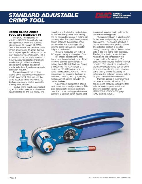
STANDARD ADJUSTABLECRIMP TOOL®DANIELSMANUFACTURINGCORPORATIONUPPER RANGE CRIMPTOOL AF8 M22520/1-01The DMC AF8 qualified toMIL-DTL-22520/1, has virtually limitlessapplication within the specifiedwire range of 12 through 26 AWG.Over a thousand turret heads or positionersare available to adapt the toolframe to your specific military or proprietarycontact/wire combination. The 8impression crimp, which is standard inthe AF8, assures absolute maximumtensile strength with almost everyclosed barrel contact. In addition,special indent configurations are availableupon request.The precision ratchet controlscycling of the tool in both directions ofhandle movement. This assures thesame accurate crimp every time. It’slike having a quality control inspectorat every work station.Positive crimp depth is controlledby an 8 position selector knob convenientlylocated on the tool frame. Theoperator simply dials the desired stepfor the wire being used. This settingcan be secured by use of a locking pinor safety wire. The carefully engineereddesign achieves the absolute maximummechanical advantage; alongwith the tool’s light weight, operatorfatigue is minimized.The AF8 measures 9 3 ⁄4″ x 2 1 ⁄2″ x1 1 ⁄4″ approximately and weighs 15 oz.For proper operation the toolframe must be mated with one of thefollowing optional accessories: amilitary head (TH-XXX Part No. Series)a turret head (TM-XXX series), apositioner (TP-XXX series), or a universalhead (part No. UH2-5). This isdone simply by orienting the head inthe keyed position, and by tighteningthe hex socket screws provided aspart of the head.A permanent dataplate is affixedto all turret heads and positioners. Thisplate lists specific contact part numbers,the corresponding position colorcode (for 3 position turret heads), andsuggested selector depth settings forthe wire size being used.The universal head is ideally suitedfor lab work and prototype productionapplications. This head is attached inthe same manner as explained above.The selected contact is insertedthrough the entry hole on the oppositeside of the tool frame from the head.The height adjusting screw is thenrotated until the contact is in theproper position for crimping. Thescrew can be secured with the locknutprovided. The wire sizes listed on thetool frame selector knob can be usedas a reference starting point; however,some testing will be necessary todetermine the optimum selector settingfor your contact/wire combination.Periodic gaging is recommendedto insure accurate calibration. Thiscan be done easily by setting the toolselector knob to position #4, andchecking indenter closure withM22520/3-1 “GO/NO-GO” gage(DMC part no. G125).PAGE 4© COPYRIGHT 2003 DANIELS MANUFACTURING CORPORATION
![G-Series-Ext [pdf] - Carling Technologies](https://img.yumpu.com/50918301/1/190x245/g-series-ext-pdf-carling-technologies.jpg?quality=85)