Technology Today 2006 Issue 3 - Raytheon
Technology Today 2006 Issue 3 - Raytheon
Technology Today 2006 Issue 3 - Raytheon

You also want an ePaper? Increase the reach of your titles
YUMPU automatically turns print PDFs into web optimized ePapers that Google loves.
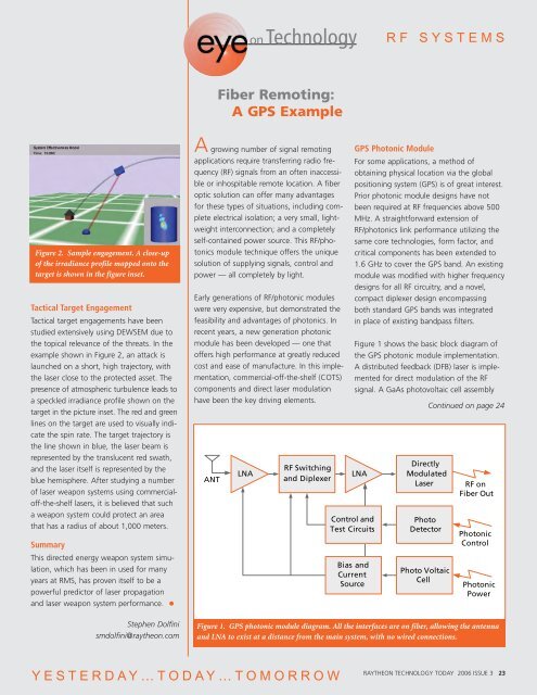
Figure 2. Sample engagement. A close-up<br />
of the irradiance profile mapped onto the<br />
target is shown in the figure inset.<br />
Tactical Target Engagement<br />
Tactical target engagements have been<br />
studied extensively using DEWSEM due to<br />
the topical relevance of the threats. In the<br />
example shown in Figure 2, an attack is<br />
launched on a short, high trajectory, with<br />
the laser close to the protected asset. The<br />
presence of atmospheric turbulence leads to<br />
a speckled irradiance profile shown on the<br />
target in the picture inset. The red and green<br />
lines on the target are used to visually indicate<br />
the spin rate. The target trajectory is<br />
the line shown in blue, the laser beam is<br />
represented by the translucent red swath,<br />
and the laser itself is represented by the<br />
blue hemisphere. After studying a number<br />
of laser weapon systems using commercialoff-the-shelf<br />
lasers, it is believed that such<br />
a weapon system could protect an area<br />
that has a radius of about 1,000 meters.<br />
Summary<br />
This directed energy weapon system simulation,<br />
which has been in used for many<br />
years at RMS, has proven itself to be a<br />
powerful predictor of laser propagation<br />
and laser weapon system performance.<br />
Stephen Dolfini<br />
smdolfini@raytheon.com<br />
on<strong>Technology</strong><br />
Fiber Remoting:<br />
A GPS Example<br />
A growing number of signal remoting<br />
applications require transferring radio frequency<br />
(RF) signals from an often inaccessible<br />
or inhospitable remote location. A fiber<br />
optic solution can offer many advantages<br />
for these types of situations, including complete<br />
electrical isolation; a very small, lightweight<br />
interconnection; and a completely<br />
self-contained power source. This RF/photonics<br />
module technique offers the unique<br />
solution of supplying signals, control and<br />
power — all completely by light.<br />
Early generations of RF/photonic modules<br />
were very expensive, but demonstrated the<br />
feasibility and advantages of photonics. In<br />
recent years, a new generation photonic<br />
module has been developed — one that<br />
offers high performance at greatly reduced<br />
cost and ease of manufacture. In this implementation,<br />
commercial-off-the-shelf (COTS)<br />
components and direct laser modulation<br />
have been the key driving elements.<br />
ANT<br />
YESTERDAY…TODAY…TOMORROW<br />
LNA<br />
RF Switching<br />
and Diplexer<br />
RF SYSTEMS<br />
GPS Photonic Module<br />
For some applications, a method of<br />
obtaining physical location via the global<br />
positioning system (GPS) is of great interest.<br />
Prior photonic module designs have not<br />
been required at RF frequencies above 500<br />
MHz. A straightforward extension of<br />
RF/photonics link performance utilizing the<br />
same core technologies, form factor, and<br />
critical components has been extended to<br />
1.6 GHz to cover the GPS band. An existing<br />
module was modified with higher frequency<br />
designs for all RF circuitry, and a novel,<br />
compact diplexer design encompassing<br />
both standard GPS bands was integrated<br />
in place of existing bandpass filters.<br />
Figure 1 shows the basic block diagram of<br />
the GPS photonic module implementation.<br />
A distributed feedback (DFB) laser is implemented<br />
for direct modulation of the RF<br />
signal. A GaAs photovoltaic cell assembly<br />
LNA<br />
Control and<br />
Test Circuits<br />
Bias and<br />
Current<br />
Source<br />
Directly<br />
Modulated<br />
Laser<br />
Photo<br />
Detector<br />
Photo Voltaic<br />
Cell<br />
Continued on page 24<br />
RF on<br />
Fiber Out<br />
Photonic<br />
Control<br />
Photonic<br />
Power<br />
Figure 1. GPS photonic module diagram. All the interfaces are on fiber, allowing the antenna<br />
and LNA to exist at a distance from the main system, with no wired connections.<br />
RAYTHEON TECHNOLOGY TODAY <strong>2006</strong> ISSUE 3 23