Vane Spindle Instructions.pdf
Vane Spindle Instructions.pdf
Vane Spindle Instructions.pdf

You also want an ePaper? Increase the reach of your titles
YUMPU automatically turns print PDFs into web optimized ePapers that Google loves.
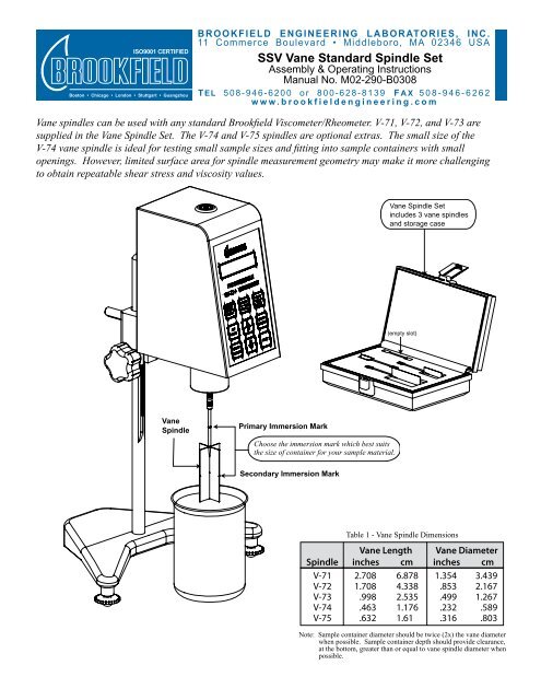
ISO9001 CERTIFIEDBoston • Chicago • London • Stuttgart • GuangzhouB R O O K F I E L D E N G I N E E R I N G L A B O R ATO R I E S , I N C .11 Commerce Boulevard • Middleboro, MA 02346 USASSV <strong>Vane</strong> Standard <strong>Spindle</strong> SetAssembly & Operating <strong>Instructions</strong>Manual No. M02-290-B0308T EL 5 0 8 - 9 4 6 - 6 2 0 0 o r 8 0 0 - 6 2 8 - 8 1 3 9 F A X 5 0 8 - 9 4 6 - 6 2 6 2w w w . b r o o k f i e l d e n g i n e e r i n g . c o m<strong>Vane</strong> spindles can be used with any standard Brookfield Viscometer/Rheometer. V-71, V-72, and V-73 aresupplied in the <strong>Vane</strong> <strong>Spindle</strong> Set. The V-74 and V-75 spindles are optional extras. The small size of theV-74 vane spindle is ideal for testing small sample sizes and fitting into sample containers with smallopenings. However, limited surface area for spindle measurement geometry may make it more challengingto obtain repeatable shear stress and viscosity values.<strong>Vane</strong> <strong>Spindle</strong> Setincludes 3 vane spindlesand storage case(empty slot)<strong>Vane</strong><strong>Spindle</strong>Primary Immersion MarkChoose the immersion mark which best suitsthe size of container for your sample material.Secondary Immersion MarkTable 1 - <strong>Vane</strong> <strong>Spindle</strong> Dimensions<strong>Vane</strong> Length <strong>Vane</strong> Diameter<strong>Spindle</strong> inches cm inches cmV-71 2.708 6.878 1.354 3.439V-72 1.708 4.338 .853 2.167V-73 .998 2.535 .499 1.267V-74 .463 1.176 .232 .589V-75 .632 1.61 .316 .803Note: Sample container diameter should be twice (2x) the vane diameterwhen possible. Sample container depth should provide clearance,at the bottom, greater than or equal to vane spindle diameter whenpossible.
<strong>Spindle</strong> Range Data<strong>Vane</strong> spindles are recommended for use with RV torque range or higher. Table 2 provides the rangedata for the RV, HA, HB and 5xHB torque ranges.Table 2 - <strong>Spindle</strong> Range Data<strong>Spindle</strong> Torque Shear Stress Range Viscosity Range cPRange Pa dyne/cm 2 (mPa•s) @ 10 rpmV-71 RV .5-5 5-50 262 - 2620V-72 RV 2-20 20-200 1110 - 11100V-73 RV 10-100 100-1000 5350 - 53500V-74 RV 100-1000 1000-10000 54300 - 543000V-75 RV 40-400 400-4000 21300 - 213000V-71 HA 1-10 10-100 524 - 5240V-72 HA 4-40 40-400 2220 - 22200V-73 HA 20-200 200-2000 10700 - 107000V-74 HA 200-2000 2000-20000 108600 - 1086000V-75 HA 80-800 800-8000 42600 - 426000V-71 HB 4-40 40-400 2096 - 20960V-72 HB 16-160 160-1600 8880 - 88800V-73 HB 80-800 800-8000 42800 - 428000V-74 HB 800-8000 8000-80000 434400 - 4344000V-75 HB 320-3200 3200-32000 170400 - 1704000V-71 5XHB 20-200 200-2000 10480 - 104800V-72 5XHB 80-800 800-8000 44400 - 444000V-73 5XHB 400-4000 4000-40000 214000 - 2140000V-74 5XHB 4000-40000 40000-400000 2172000 - 21720000V-75 5XHB 1600-16000 16000-160000 852000 - 8520000Notes: 1) 1 Pa = 10 dyne/cm22) 1 cP = 1 mPa•s3) Possibility of turbulence at speeds above 10 rpm may give artificially higher viscosity readings.Viscometer OperationAttach the <strong>Vane</strong> <strong>Spindle</strong> to your Viscometer as shown in the illustration on page one (Note: spindleshave a left-hand thread for installation). Immerse the <strong>Vane</strong> <strong>Spindle</strong> into the fluid past the top of the<strong>Vane</strong> to the primary immersion mark on the shaft. Operate your Viscometer per the instructions in theOperator’s Manual that came with your instrument. Record the instrument Speed (in RPM) and theTorque Reading (as a percent). The Viscosity is calculated manually using the following equation:Viscosity (cP) = 100* TK * SMC * TorqueRPMwhereRPM = Viscometer spindle speed in RPMTK = Viscometer torque constant from Table 3SMC = <strong>Spindle</strong> multiplier constant from Table 4Torque = Viscometer torque (%) expressed as anumber between 0 and 100If the secondary immersion mark (midpoint of the vane)is chosen due to small container size, multiply the torquereading by a factor of two (2).Viscosity (cP) = 100* TK * SMC * 2xTorqueRPMTable 3 - Viscometer Torque ConstantsModelTKRV 1HA 2HB 85xHB 40Table 4 - <strong>Spindle</strong> Multiplier Constants<strong>Spindle</strong>SMCV-71 2.62V-72 11.1V-73 53.5V-74 543V-75 213