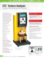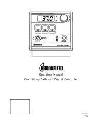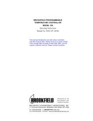
Operators Manual Circulating Bath with Digital Controller
Operators Manual Circulating Bath with Digital Controller
Operators Manual Circulating Bath with Digital Controller

Create successful ePaper yourself
Turn your PDF publications into a flip-book with our unique Google optimized e-Paper software.
Table of ContentsSection 1. General Information1.1 Unpacking1.2 Package Contents1.3 Description of <strong>Circulating</strong> <strong>Bath</strong>1.4 Specification1.5 <strong>Circulating</strong> <strong>Bath</strong> Fluid Connections To External ApparatusSection 2. Operation2.1 Location2.2 Filling the Reservoir2.3 Reservoir Fluids2.4 Circulator Pump2.5 Closed Loop Circulation2.6 Power2.7 Setting Temperature2.8 Setting the High Limit2.9 Setting the Safety Thermostat2.10 Operation of Refrigerated Models2.11 Operation of Heat-Only Models2.12 Selection of Celsius or Fahrenheit Readout2.13 Optimization of <strong>Controller</strong>2.14 <strong>Controller</strong> Display MessagesSection 3. Maintenance3.1 Heater3.2 Pump Motor3.3 Condenser and Air Vents (Refrigerated Models)3.4 Cleaning3.5 Maintaining Clear <strong>Bath</strong> WaterSection 4. Troubleshooting4.1 Unit Disabled - Service Required4.2 No Pumping4.3 Insufficient Pumping4.4 No Cooling or Insufficient Cooling4.5 No Heating4.6 Insufficient Heating4.7 Triac Failure4.8 <strong>Controller</strong> Default SettingsSection 5.Service and Technical SupportSection 6.After-sale SupportSection7.Warranty3
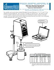
Section 1. General Information1.2 UnpackingYour circulator is shipped in a special carton. Retain the carton and all packing materials until the unitis completely assembled and working properly. Set up and run the unit immediately to confirm properoperation. Beyond one week, your unit may be warranty repaired, but not replaced. If the unit isdamaged or does not operate properly, contact the transportation company, file a damage claim andcontact the company where your unit was purchased.Remove any loose packing material which may have fallen into the reservoir during shipping. Alsocheck that nothing remains around the heater or circulator pump. Before proceeding, be sure thePower switch is in the OFF position. Refrigerated models should have the Cooling switch in the OFFposition.1.2 Package ContentsCirculator <strong>Bath</strong><strong>Operators</strong> <strong>Manual</strong> 110-1193/ 16 in., 1 / 4 in., and 3 / 8 in. Nylon Barbed Tubing Adapters 510-0116 ft. of 1 / 4 in. ID Latex Tubing 300-299All TC-101D TC-201D TC-501DBeaker Platform(s) for <strong>Bath</strong> Reservoir — 600 ml 701-402 701-402 (qty 2) 701-402— 1000ml 701-403Deck Lid(s) — solid 510-209 510-209— w/beaker holes 510-211 510-209 510-211Blue Hole Plugs — 3 1 /2inch 300-295 300-295(qty 2) 300-295Note: Do NOT Use Above 120°C — 4 1 /4inch 300-296Note: Work area "opening" is designed to measure samples directly in the bath. If additional viscometer heightis required (spindle/guard clearance), either a 4 inch rod extension (part number BLM-4E) used <strong>with</strong> type A labstand or an 18 inch rod replacement (part mumber VS-38)used <strong>with</strong> type S lab stand are available fromBrookfield or an authorized dealer.1.4 Description of <strong>Circulating</strong> <strong>Bath</strong><strong>Digital</strong> controller refrigerated and heating circulating baths are designed to provide precise temperaturecontrol of fluids for closed loop circulation to external equipment or to be used as a stand alonebath. The reservoir may be used for immersing samples while the unit is connected to an externaldevice. All wetted parts are corrosion resistant 300 series stainless steel. Models are equipped <strong>with</strong>various size reservoirs.1.5 Specification<strong>Controller</strong><strong>Digital</strong>Temperature Range (non-refrigerated) Ambient +5° to 150°CTemperature Range (refrigerated) -20° to 150°CTemperature StabilityReadout AccuracyReadoutPumpPump Flow Rate (Pressure) @ 120V / 60 HzOver temperature / Safety CutoffRS-232 InterfaceHeater±0.05°C±0.5°CLEDSimplex15 lpm & 9 lpmYes (adjustable)Yes1000 Watts4
1.5 Specification, continuedModel TC-101D TC-201D TC-501DDimensions (in.) 14 3 / 4 x 8 1 / 4 x 14 13 1 / 4 x 14 1 / 4 x 13 1 / 4 15 3 / 4 x 18 3 / 4 x 17(l x w x h) (cm) 37.5 x 13.3 x 35.6 33.7 x 36.2 x 33.7 40 x 47.6 x 43.2Unit Weights 22 lbs (10.0 kg) 28 lbs (12.7 kg) 63 lbs (28.6 kg)Reservoir Volumes 6 liters 10 liters 6 litersPower Requirement 9A @ 115V / 1 / 60Hz 9A @ 115V / 1 / 60Hz 10A @ 115V / 1 / 60Hz(105V - 125V) (105V - 125V) (105V - 125V)4.5A @ 240V / 1 / 50Hz 4.5A @ 240V / 1 / 50Hz 5A @ 240V / 1 / 50Hz(200V - 260V) (200V - 260V) (200V - 260V)1.6 <strong>Circulating</strong> <strong>Bath</strong> Fluid Connections To External ApparatusOn circulating baths, the pump inlet and outlet are internally threaded <strong>with</strong> female 1 / 4 inch NPT to allowuse of barbed tubing adapters or hard plumbing. Or, you can slide 1 / 2 inch (13mm) ID tubing overeach pipe and hold it in place <strong>with</strong> a hose clamp.Select tubing and fittings that are compatible <strong>with</strong> bath fluid and temperature range. If the pump inletand outlet are not used for external circulation, for best results connect the inlet and outlet pipes <strong>with</strong> ashort length of insulated tubing. Or, plug the pipes <strong>with</strong> male nylon plugs (supplied) or <strong>with</strong> metalplugs (not supplied) for high temperature use.The nylon barbed tubing adapter fittings supplied are for applications from -20° to 93°C. Brass,stainless steel or Teflon® fittings are recommended for applications above 93°C. Quick connectors arenot recommended as they typically restrict flow rate.Section 2. Operation2.1 LocationLocate your circulator on a level surface free from drafts and direct sunlight. Do not place it wherethere are corrosive fumes, excessive moisture, high room temperatures, or excessively dusty areas.Refrigerated circulators must be four inches minimum away from walls or vertical surfaces so air flow isnot restricted. Avoid voltage drops by using properly grounded power outlets wired <strong>with</strong> 14 gauge orlarger diameter wire and if possible, be close to the power distribution panel. The use of extensioncords is not recommended, this will avoid low line voltage problems.2.2 Filling the ReservoirThe maximum fill level is one inch below the top of the reservoir. When in operation, add additionalfluid to compensate for any additional volume needed for external circulation. Minimum liquid depth isenough to fully cover the heater, pump, and one inch of the temperature sensor. If the proper fluid levelis not maintained, the heater coil may become exposed and possible damage to the heater may result.Warning: These units are equipped <strong>with</strong> Over Temperature Protection (OTP). Failure due to lowliquid level or failure to set OTP and properly immerse the heater may result in heater burnoutand triac failure. While operating, do not allow the heater to contact any potentially flammablematerials such as plastic racks or sides of plastic tanks as a fire hazard may result.5
2.3 Reservoir FluidsUse distilled water for temperatures from 10° to 100°C or a mixture of laboratory grade ethylene glycoland water for temperatures below -20°C. The fluid must be chemically compatible <strong>with</strong> the reservoirand <strong>with</strong> 300 series stainless steel in the pump and heater. The fluid must also be able to produce thetemperature range desired.For temperature stability of ±.05°C, the viscosity should be 50 centistokes or less at the lowestoperating temperature to allow good fluid circulation and to minimize heating from the pump. Most heattranser fluids will be able to stabilize to ±.05°C over a 100°C range. Use fluids that will satisfy safety,health and equipment compatibility requirements.The chart below will help in selecting a fluid for your application. Stay <strong>with</strong>in the fluid’s normal range forbest temperature stability, low vaporization, and safety.You are responsible for proper selection and use of the fluids.Extreme range operation should be avoided.FLUID DESCRIPTION SPECIFIC HEAT NORMAL EXTREME@25°C RANGE RANGEWater 1.00 10°C — 90°C 2°C — 100°CEthylene Glycol 30% / Water 70% .90 0°C — 95°C -15°C — 107°CEthylene Glycol 50% / Water 50% .82 -20°C — 100°C -30°C — 100°CEthylene Glycol 100% .62 50°C — 125°C 0°C — 125°C*Dynalene-HC 50 .76 -50°C — 60°C -62°C — 60°CDC510 50 cs Silicone Oil .39 50°C — 150°C 5°C — 270°C*DC550 125 cs Silicone Oil .42 100°C — 200°C 80°C — 315°C**WARNING - Fluid’s flashpoint temperature.DC fluids are manufactured by Dow Corning. Dynalene HC is a registered TM of Advanced Fluid Technologies, Inc.DO NOT USE THE FOLLOWING FLUIDS:1. Automotive antifreeze <strong>with</strong> additives*2. Hard tap water*3. Deionized water <strong>with</strong> a specific resistance > 1 meg ohm4. Any flammable fluids5. Concentrations of acid or bases6. Solutions <strong>with</strong> halides: chlorides, fluorides, bromides, iodides or sulfur7. Bleach (Sodium Hypochlorite)8. Solutions <strong>with</strong> chromates or chromium salts* At temperatures above 40°C, additives or mineral deposits can adhere to the heater. If allowed to build up, the heatermay overheat and fail. Higher temperatures and higher concentrations of additives will cause a faster deposit build up.If buildup occurs see Section 3 Maintenance - Heater.WARNING: Do not use a flammable liquid as a fire hazard may result.6
APPLICATION NOTESAt fluid's low temperature extreme:1. Presence of ice or slush will adversely affect temperature stability.2. Viscosity above 10 centistokes will adversely affect temperature uniformity.3. High fluid viscosity and high speed pumping will generate heat in the fluid.At fluid’s temperature above ambient <strong>with</strong>out using refrigeration:1. Without refrigeration and <strong>with</strong>in 15°C of room temperature the viscosity should be 10 centistokes orless to avoid friction heating of the fluid. Encourage heat loss by uncovering the fluid and loweringpump speed.At fluid’s high temperature extreme:1. Heat loss from vapor will cause poor temperature stability.2. A fume hood may be required to prevent the buildup of vapors inside the room.3. Use a cover and/or floating hollow balls to help prevent heat and vapor loss.4. Fluid lost from vapor will have to be frequently replenished.2.4 Circulator PumpThe two speed pressure (simplex) pump may be used for tempering of samples in the reservoir or forcirculation in closed loops. It is not designed for pumping from the circulator's reservoir into and out ofa second open reservoir. The HI or LO speed selection switch on the rear panel of the controller allowsa choice of pump speeds.Maximum PumpMaximum PumpSpeed Outlet Ratings Outlet RatingsSelection Line Frequency = 60Hz Line Frequency = 50HzHI 15 lpm / 2.6 psi 10.4 lpm / 1.8 psiLO 7 lpm / 1.3 psi 4.8 lpm / 0.9 psiThe table uses the following criteria:1. Maximum pump outlet flow rate is measured in liters per minute (lpm) <strong>with</strong> no restriction on thepump outlet.2. Maximum pump outlet pressure is measured in pounds per square inch (psi) at no flow.3. Water was used as the circulation fluid. Water has a viscosity of one centistoke. High viscosity orlow density fluids will change these figures.4. When the inlet and outlet are plugged on reservoir models, flow rate refers to internal bathcirculation.Select the HI pump speed where changes in temperature vary and there is a need for fast recovery,or when pumping to multiple external units. The LO pump speed is adequate for most applicationsand provides quieter pumping.2.5 Closed Loop CirculationConnect the pump inlet and outlet to your application. Use care to avoid restrictions in the tubing inorder to maintain adequate flow. When connecting to more than five closed loops we recommend useof a manifold made of "Y" adapters to divide the fluid into two or more banks. A booster pump may beadded <strong>with</strong>out damage to the circulation bath pump. After setting up multiple closed loops, check thatthere is adequate flow at the return manifold for each loop and recheck bath fluid level.The control stability of a closed loop system will generally be better at the external apparatus than inthe immediate vicinity of the heater, provided the apparatus control point represents a constant loadand is well insulated For example, if you circulate at 50°C through a viscometer, the temperaturevariation observed in the reservoir may be +0.05°C, whereas in the viscometer it may be only +0.02°C.7
Although stability is better at the external apparatus control point, depending on the insulation andlength of tubing used, the accuracy of temperature may be slightly different than the temperatureindicated in the reservoir.2.6 PowerPlug the unit into a properly wired, grounded outlet <strong>with</strong> the same voltage and frequency indicated onthe identification label on the back of the unit. With the Power switch OFF, the display indicatesstandby mode (....). If there is no response, check if the circuit breaker is in the ON position.Use of an extension cord is not recommended, but if necessary, use one that is properly grounded andhandles the total wattage of the unit. The extension cord must not cause more than a 10% voltage drop tothe circulator.INCREASEINCREASEDECREASEDECREASESETENTERSETENTERSTATUSCOOLINGHEATINGSTATUSHEATINGCOOLINGPOWERONOFFPOWERONOFFONOFFFront ViewRefrigerated & Heating ModelsFront ViewHeating Models2.7 Setting the TemperatureAfter filling the reservoir <strong>with</strong> fluid, set the temperature:1. Set the Safety Thermostat (OTP) knob on the rear panel to full clockwise position, then press thePower switch ON. The pump starts to operate. The LED display indicates the power up self-test(8888). You are now ready to set the front panel controls to the desired temperature setting.2. Press the SET/ENTER button. The degree light flashes indicating the temperature can be changed.3. Turn the INCREASE/DECREASE knob to the desired setting. This setting is accepted afterpressing the SET/ENTER button or automatically accepted after a few seconds. The degree lightstops flashing and the display indicates the actual bath temperature.The set temperature may be checked at any time by pressing the SET/ENTER button. Allow sufficienttime for the bath to stabilize at the desired temperature.If you are unable to raise the set temperature, it is possible that the High Limit is set lower than the settemperature you have selected. If this happens, set the High Limit to be 1°C or more higher than yourdesired temperature.2.8 Setting the High LimitThis feature provides additional set point security by allowing a selectable upper limit set point. If thefluid reaches the high limit, the unit will shut down and display "HI-L" until the fluid temperature isreduced or the "HI-L" value is raised. The "HI-L" should be at least 1°C higher than the selected controltemperature to avoid unwanted shut down during regular operation.8
TO SET THE HIGH LIMIT TEMPERATURE:1. Press and hold the SET/ENTER button until the display reads "UNIT".2. Turn the INCREASE/DECREASE knob until the display reads "HI-L".3. Press the SET/ENTER button and enter the desired value using the INCREASE/DECREASE knob.4. Press SET/ENTER or the setting will be accepted after a few seconds.2.9 Setting the Safety ThermostatThe Over Temperature Protection (OTP) thermostat safety feature prevents your unit from burnout incase of primary controller failure or a low liquid condition by switching off power to the heater. Thisfeature is independent of the high limit setting and has a range of 60°C to 220°C The high limit asindicated in Section 2.3 (above) must still be set.For temperatures less than 60°C:1. Turn the OTP knob located at the rear of the controller fully counterclockwise (minimum setting)Note: 240V models have a recessed slot that is to be set <strong>with</strong> a standard screwdriver.For temperatures over 60°C:1. Turn the adjustable thermostat, OTP knob, (on controller's back) fully clockwise (maximum+)until it stops.2. Stabilize the bath at the maximum desired control temperature.3. Turn the OTP knob slowly counter-clockwise until you hear a click. The unit stops and the displaywill read "E-oP" (Over temperature).4. Turn the OTP knob clockwise slightly above the position where the unit tripped then reset the OTPbreaker by pressing the red OTP reset button (below the knob). OTP is now set to trip a fewdegrees over the stabilized fluid temperature.2.10 Operation of Refrigerated ModelsFor operation at temperatures below 40°C, refrigeration is normally required. To start the refrigerationsystem, press the cooling switch to the ON position. The refrigeration automatically shuts down if thebath fluid is above 80°C, even if the refrigeration switch is on.When refrigeration is switched off, it should NOT be restarted for approximately 10 minutes to allow the internalpressures to equalize. System damage could result if you do not observe this waiting period.2.11 Operation of Heat-Only ModelsFor operation of non-refrigerated models, the included cooling coil may be used to achieve bathtemperatures <strong>with</strong>in 15°C above the ambient room temperature. The cooling coil also permits the bathtemperature to be lowered more rapidly, after operation at an elevated temperature. The cooling coilconnections are located between the circulating pump’s inlet and outlet connections at the rear of thebath’s controller. To use the cooling coil, slide the 1 / 4 inch ID latex tubing from the water source over oneof the coil’s connections and route another length of tubing from the other coil connection to the drain.2.12 Selection of Celsius or Fahrenheit ReadoutTo change the readout to display in °F or °C:1. Press and hold the SET/ENTER button until the display reads "UNIT".2. Press SET/ENTER again then turn the INCREASE/DECREASE knob and select °C or °F.3. Press SET/ENTER or the setting is accepted after a few seconds.9
2.13 Optimization of <strong>Controller</strong>There is provision to optimize the the controller for special applications. If the temperature stabilityusing factory settings is satisfactory, there is no need to change the controller tuning.Control performance equal to or greater than ± 5°C from the setpoint temperature is not affected bytuning. To achieve close control, tuning may be necessary if you use: a closed loop system of largevolume; a fluid other than water; or a viscous fluid.Tuning of Proportional Integral Derivative (PID) controllers requires extensive knowledge of PIDtechnology or time lost in pure guesswork. The tuning parameters below are simplified and are figuresthat can be easily measured and entered. Settings are not critical, estimates are acceptable.Each of the three values used for tuning can be changed <strong>with</strong>out having to change any other value.Each value is independent.TO CHANGE THE TUNING:Press and hold the SET/ENTER button until the display reads "UNIT".Turn the INCREASE/DECREASE knob until the display reads "CAP" - Capacity.1. Press SET/ENTER.2. Enter the estimated total system volume in liters using the INCREASE/DECREASE knob.3. Press SET/ENTER or setting is accepted after a few seconds.Turn the INCREASE/DECREASE knob until the display reads "FLO" - Flow Rate.1. Press SET/ENTER.2. Enter the estimated actual flow rate in liters per minute using the INCREASE/DECREASE knob.3. Press SET/ENTER or setting is accepted after a few seconds.Turn the INCREASE/DECREASE knob until the display reads "SHC"- Specific Heat Capacity.1. Press SET/ENTER.2. Enter the specific heat capacity of the fluid being used by using the INCREASE/DECREASE knob.3. Press SET/ENTER or setting is accepted after a few seconds.Refer to Section 2.3 Reservoir Fluids for specific heat values of various liquids and Section 4.8<strong>Controller</strong> Default Settings for returning to factory default controller settings.2.14 <strong>Controller</strong> Display MessagesNormal ScreensMenu ScreensDisplay Message.... Standby mode. Unit plugged in. Power switch OFF.8888 Power up self-test. Power switch ON.FLO Flow rate selection for controller tuningCAP Capacity (volume) for controller tuningSHC Specific heat value for controller tuningUnit Change to °F or °C10Error ScreensAL-ME-oPE-5FE-tFHigh temperature alarmOver temperature faultSensor failureTriac (alternistor) failure
Section 3. Maintenance3.1 HeaterThe heater should be kept clean. If deposits build up on the heater they may be removed by scouring<strong>with</strong> a non-metallic (plastic) abrasive pad. Do NOT use steel wool, it causes stainless steel to rust.3.2 Pump MotorThe top and bottom bearings are permanently lubricated <strong>with</strong> a high temperature silicone grease.They should not require lubrication. The pump motor bearings are not available separately. If thebearings become noisy, we recommend replacement of the entire motor to save cost in labor andretain reliability. A replacement pump and motor mounting kit is available.3.3 Condenser and Air Vents (Refrigerated Models)The condenser and the right and left air vents should be kept free of dust and dirt. Dirt thermallyinsulates the condenser and reduces the cooling capacity of the refrigeration system. Set up a periodicschedule to clean the fins of the condenser <strong>with</strong> compressed air.3.4 CleaningUse only mild detergent and water or an approved cleaner on the painted and stainless steel surfaces.Do not allow cleaning liquids or sprays to enter the controller head vents.3.5 Maintaining Clear <strong>Bath</strong> WaterOptimum temperature and moisture conditions for algae growth exist when using water as the bathfluid. To prevent algae contamination and to minimize frequency of draining the reservoir, an algicideshould be used. Do NOT use Chlorine Bleach.Section 4. Troubleshooting4.1 Unit Disabled - Service Required• Check the power to the unit. • Be sure circuit breaker is on. • Try unplugging the unit andplugging in again to fully reset the system. • If the unit continues to display an error message or nomessage, request service.4.2 No Pumping• If the pump motor does not spin, check the Hi-Lo pump speed switch is all the way up or down. If itis in the middle, the pump will not receive power. • Check the pump impeller turns freely. • Checkfluid level of the bath to be sure the pump head is covered <strong>with</strong> fluid.4.3 Insufficient Pumping• Check for low line voltage, especially when the heater is on. • Hose diameter may be too small.• Fluid viscosity may be high.11
4.4 No Cooling or Insufficient Cooling• Check the Cooling switch is ON, the cooling light should also be on. • Check for low or high linevoltage. • Check for blocked airflow through ventilation screens. • Refrigeration unit should NOT beoperated above 32°C ambient temperature, such a condition may cause the refrigeration compressorto temporarily shut down. • Check if heat is being added to the fluid in excess of the refrigerationsystem’s capacity.4.5 No Heating• Check if the unit is pumping properly. • If the heat light is not on, check the setting of the setpointtemperature and bath temperature. • Be sure HI limit setting is higher than the setpoint. • Check fluidlevel of the bath to be sure the heater is covered.4.6 Insufficient Heating• Check if the unit is pumping properly. • Check for proper line voltage. • Check for excessiveexternal cooling load on unit At higher temperatures, problem could be due to heat loss from tanks,hoses or vapor from the tank. Variance of heat load on the system from experiments may exceed thepower handling of the unit. Changes in heat load or setpoint will require some time to settle to a stabletemperature.4.7 Triac Failure• Display shows "E-tF". Heater triac has failed or line supply voltage has a source of extremeinterference from other equipment. • Try the unit on another power source. • If it still displays triacfailure, a triac or triac driver needs replacement.4.8 <strong>Controller</strong> Default SettingsShould the need arise, use the following steps to return all settings to the factory default values.1. Turn the Power switch ON, then unplug the power cord.2. With the Power switch still ON, press and hold the SET/ENTER button while plugging the powercord in.3. The controller will display "DEF" and go to the standby mode.4. Control point and high limit settings will have to be reset. Any special tuning settings will also haveto be reset. OTP is not affected by default resetting, but should be checked again.Section 5. Service and Technical SupportIf you have followed the troubleshooting steps and your circulator fails to operate properly, contact thedistributor or manufacturer from whom the unit was purchased. Have the following information availablefor the customer service person:— Model and Serial Number— Voltage (from back panel label)— Date of purchase and your purchase order number— Suppliers' order number or invoice number— A summary of your problem12
Section 6. After-sale SupportAll instruments requiring warranty repair must be returned to Brookfield Engineering Laboratories, Inc.or the Brookfield dealer from whom it was purchased. Transportation is at the purchaser's expense.For repair or service in the United States, return to:Brookfield Engineering Labs., Inc.11 Commerce BoulevardMiddleboro, MA 02346 USATelephone: 508-946-6200Fax: 508-946-6262URL: www.brookfield.comservice@brookfieldengineering.comFor repair or service outside the United States, consult Brookfield Engineering Laboratories, Inc.or the dealer from whom you purchased the instrument.For repair or service in the United Kingdom, return to :Brookfield Viscometers Limited1 Whitehall EstateFlex MeadowPinnacles WestHarlow, Essex CM19 5TJ, United KingdomTelephone (44) 27/945-1774Fax: (44) 27/945-1775service@brookfield.co.ulFor repair or service in Germany, return to:Brookfield Engineering Labs. Vertriebs GmbHBarbarossastrasse 3D-73547 Lorch, GermanyTelephone: 7172/927100Fax: 7172/927105info@brookfield-gmbh.de13
Section 7. WarrantyThank you for your purchase. We are confident it will serve you for a long time. Our warranty to you isas follows:The manufacturer agrees to correct for the original user of this product, either by repair, or at themanufacturer’s election, by replacement, any defect which develops after delivery of this product <strong>with</strong>inthe period as stated on the warranty card. In the event of replacement, the replacement unit will bewarranted for 90 days or warranted for the remainder of the original unit’s parts or labor warrantyperiod, whichever is longer.If this product should require service, contact the manufacturer/suppliers’ office for instructions. Whenreturn of the product is necessary, a return authorization number will be assigned and the productshould be shipped, transportation charges pre-paid, to the indicated service center. To insure prompthandling, the return authorization number should be placed on the outside of the package and adetailed explanation of the defect enclosed <strong>with</strong> the item.This warranty shall not apply if the defect or malfunction was caused by accident, neglect,unreasonable use, improper service, or other causes not arising out of defects in material orworkmanship. There are no warranties, expressed or implied, including, but not limited to, those ofmerchantability or fitness for a particular purpose which extends beyond the description and period setforth herein.The manufacturer’s sole obligation under this warranty is limited to the repair or replacement of adefective product and the manufacturer shall not, in any event, be liable for any incidental orconsequential damages of any kind resulting from use or possession of this product.Some states do not allow: (A) limitations on how long an implied warranty lasts or (B) the exclusion orlimitation of incidental or consequential damages, so the above limitations or exclusions may not applyto you. This warranty gives you specific legal rights. You may also have other rights which vary fromstate to state.14