BROOKFIELD YR-1 RHEOMETER Operating Instructions Manual ...
BROOKFIELD YR-1 RHEOMETER Operating Instructions Manual ...
BROOKFIELD YR-1 RHEOMETER Operating Instructions Manual ...

You also want an ePaper? Increase the reach of your titles
YUMPU automatically turns print PDFs into web optimized ePapers that Google loves.
<strong>BROOKFIELD</strong> <strong>YR</strong>-1 <strong>RHEOMETER</strong><strong>Operating</strong> <strong>Instructions</strong><strong>Manual</strong> No. M/02-215SPECIALISTS IN THEMEASUREMENT ANDCONTROL OF VISCOSITY<strong>BROOKFIELD</strong> ENGINEERING LABORATORIES, INC.11 Commerce Boulevard, Middleboro, MA 02346-1031 USATEL 508-946-6200FAX 508-946-6262or 800-628-8139 (USA only)INTERNET www.brookfieldengineering.comBrookfield Engineering Labs., Inc. Page 1 <strong>Manual</strong> No. M/02-215
7) If appropriate, connect interconnecting cable to serial port for connection of <strong>YR</strong>-1 to PC orprinter.8) If appropriate, connect interconnecting cable to parallel port for connection of <strong>YR</strong>-1 toprinter.9) If appropriate, connect interconnecting cable to analog (serial) port for connection of <strong>YR</strong>-1to chart recorder.I.5 Key FunctionsThe following explains the functions of the control keys on the face of the <strong>YR</strong>-1 YieldRheometer.UP ARROWUsed to scroll UP (in an increasing direction) through the menu and programselections.DOWN ARROWUsed to scroll DOWN (in a decreasing direction) through the menu and programselections.ENTERENTERUsed to accept or activate the current selection.ESCESCAPEUsed to cancel an operation or return to a previous screen.Note: Selections are indicated as flashing text on the screen display.Brookfield Engineering Labs., Inc. Page 6 <strong>Manual</strong> No. M/02-215
Once the sample is prepared and the ENTER key is pressed with a valid program displayed, thefollowing screen is displayed:USE SPINDLE #71PRESS ENTERFigure 8where the two (2) digit spindle number is displayed on the top line. Attach the appropriatespindle and lower it into the sample before continuing.Pressing the ENTER key with Figure 8 displayed performs the following:• The test is started.• The pre-test information (test parameters) is sent to both the serial (RS-232) port and toan attached printer via the parallel printer port. See section III.3 for a description of thepre-test information sent to the printer.• The program number being run is recorded so that it will be the first program shown thenext time that START TEST is selected from the Default Screen (Figure 5).Pressing the ESC key at this screen causes Figure 7 to be displayed.After ensuring the appropriate spindle is attached and pressing the ENTER key, the variousRun screens are displayed. The top line of the Run screens always displays the program andspindle number as follows:TEST #5 SPDL 71----------------Figure 9where the program and spindle numbers in use are displayed on the top line. The bottom lineof the Run screens vary depending upon the options selected in the program.Figure 10 is displayed when a Pre-Shear speed and time were selected. If the current programrequires a Pre-shear step, the spindle will rotate at the selected speed for the selectedtime. The first field after the word SHEAR is the speed of the pre-shear (in rpm) while thesecond field is a time (in seconds) that counts down from the user defined pre-shear time. APre-shear step allows the sample to be conditioned before the actual test is started. In Figure10, the pre-shear speed is 10 rpm and the pre-shear time is 30 seconds.TEST #5 SPDL 71SHEAR: 010 0030Figure 10Figure 11 is displayed when a Zero operation was selected. If the current program requires aZero step, the spindle rotates backwards until the % torque reading is zero (0). The first fieldafter the word ZEROING is the speed (in rpm) while the second field is the current % torquereading. A Zero step ensures that each test is started from 0% torque. In Figure 11, thespeed is .2 rpm and the torque reading is momentarily at 2.4% as it decreases back to 0%.Brookfield Engineering Labs., Inc. Page 9 <strong>Manual</strong> No. M/02-215
II.6 Test ResultsII.6.1Test PassedWhen a yield test runs successfully, the resultant Yield Stress (Pa), the % Torque value at thetime of the yield and the Temperature at yield are printed.Test (#5: Sample Tst) CompleteYield Stress (Pa) = 726.36 % Torque @ Yield = 73.56 Temperature = 25.5CIn addition, the results are shown on the display as follows:II.6.2 Test Failed%=73.56 025.5CYIELD=726.36 PaFigure 21Some of the reasons a yield test may fail are as follows.II.6.2.1 Under-Range ConditionOnly yield measurements in the % Torque range from 10% to 100% will be accepted. Ifa Yield Stress is reached before the % Torque value is 10%, an Under-Range error causes thetest to end.The following is sent to an attached printer:Test (#5: Sample Tst) CompleteTest Failed = Under-rangeThe following screen is displayed:YIELD ERRORUNDER-RANGEFigure 22II.6.2.2 Over-Range ConditionOnly yield measurements in the % Torque range from 10% to 100% will be accepted. IfYield Stress is not reached before the measured % Torque value reaches 100%, an Over-Range error causes the test to end.The following is sent to an attached printer:Test (#5: Sample Tst) CompleteTest Failed = Over-rangeThe following screen is displayed:YIELD ERROROVER-RANGEFigure 23Brookfield Engineering Labs., Inc. Page 14 <strong>Manual</strong> No. M/02-215
II.6.2.3 User-Defined Limit ConditionWhen an upper and lower limit has been imposed upon the Yield Stress by the user, anyresulting Yield Stress that falls outside these limits causes the test to fail with a LimitViolation Condition. One of the following messages is sent to the attached printer dependentupon which limit was violated:Low Limit ViolationTest (#5: Sample Tst) CompleteYield Stress (Pa) = 196.53 % Torque @ Yield = 27.4 Temperature = 250.5CTest Failed = Yield Stress Below Low LimitHigh Limit ViolationTest (#5: Sample Tst) CompleteYield Stress (Pa) = 996.53 % Torque @ Yield = 78.6 Temperature = 250.5CTest Failed = Yield Stress Above High LimitThe following screen, showing first the violated limit value followed by the resultingYield Stress, is displayed:II.6.2.4 Test Cancelled By UserLIMITS EXCEEDEDYLD:800 (996.53)Figure 24When a test is cancelled by the user, either by pressing the ESC key during a running testor by canceling the test via the EZ-Yield software (See Section II.4.6), the following issent to the attached printer:Test (#test number: test name) CancelledTest Failed = Cancelled By UserThe following screen is displayed:TEST TERMINATEDBY USERFigure 25Brookfield Engineering Labs., Inc. Page 15 <strong>Manual</strong> No. M/02-215
III. EZ-YIELD SOFTWAREBrookfield EZ-Yield software is a 32-bit Windows program supplied with every <strong>YR</strong>-1 YieldRheometer.III.1 EZ-Yield OverviewEZ-Yield provides the following features:• EZ-Yield allows you to easily create a yield test and download it to one of the ten (10) memorylocations in the <strong>YR</strong>-1 Rheometer. These programs are retained in memory so that the <strong>YR</strong>-1 can be disconnected from the PC and used in remote locations (i.e. in a Q.C. laboratory, theproduction floor, etc.). Test programs can be saved and printed from the host PC.• EZ-Yield collects all the data from a yield test run in addition to the final Yield Stress. Thisdata can be saved, printed, and graphed using the software.III.2 EZ-Yield Quick Start1. Ensure the <strong>YR</strong>-1 is powered on and ready to accept test programs (See Section II – GettingStarted).2. Ensure the appropriate serial (RS-232) cable (Brookfield Part # DVP-80) is connected to theserial port of the <strong>YR</strong>-1 and a serial port (COM port) on the host PC.3. Start the EZ-Yield software in one of the following manners:• Click on its associated icon.• Click the Windows Start button. Select Run. Enter the name “ezyield.exe” of theprogram (including path) and click OK to execute EZ-Yield.4. Once EZ-Yield is running, set the COM Port setting on the toolbar to the appropriate COMport.5. Click on the Test Parameters tab beneath the toolbar. Select the appropriate values for allthe test parameters listed at the left of the Test Parameter page. See Section III.3 for moreinformation regarding how to select Test Parameters. Save the test parameters if desired byclicking the Save button or by clicking Save on the File menu.6. Click the Download button on the toolbar or click Download Program in the Utility menu.7. Ensure the appropriate spindle is attached to the <strong>YR</strong>-1 and that the sample is properlyprepared.8. Click the down arrow on the Run button or click Run Program on the Utility menu. Selectthe program number you wish to run, in this case, the Program Number specified in the listof Test Parameters.9. After a few seconds, the Graphs page is automatically displayed signaling that the test hasbegun. Once all optional preparation steps are complete, the <strong>YR</strong>-1 begins sending data to theEZ-Yield software and displaying it on the graph and in the data table on the Data page.10. When the test is complete, a dialog box appears asking you to save the data just acquired.Brookfield Engineering Labs., Inc. Page 16 <strong>Manual</strong> No. M/02-215
III.3 Test Parameter DescriptionIII.3.1 Program NumberThis is the number of the memory slot in the <strong>YR</strong>-1 Rheometer to which the test parameterswill be loaded. There are ten (10) slots, numbered from 0 through 9.III.3.2 Program NameThis descriptive user-supplied name is loaded into the memory slot in the <strong>YR</strong>-1 Rheometerwith the test parameters. A maximum of ten (10) alphanumeric characters may be used forthis name.III.3.3 SpindleSpindle NumberA two (2) digit code representing the spindle number used for the testmust be selected. See Appendix A for more information regardingspindles for use with the <strong>YR</strong>-1 Rheometer. Selection of the appropriatespindle is important to ensure appropriate stress calculations.Immersion MarkEach vane spindle has two (2) immersion marks. The primaryimmersion mark is located on the spindle shaft. Normally, the spindleshould be inserted so that the sample reaches this mark. If the samplecontainer is too small to allow the spindle to be inserted to this mark,the secondary immersion mark may be used. This mark appears halfway down the blades of the vane spindles. See Appendix A for moreinformation regarding spindles and immersion marks.PrimaryImmersionMarkSecondaryImmersionMarkNote:Selection of the appropriate immersion mark is important to ensure appropriate stresscalculations.III.3.4 Pre-Shear InformationAn optional Pre-Shear step can be included in the test parameters. If the Pre-Shear box is checkedon the Test Parameter page of the EZ-Yield software, a pre-shear step will be performed beforerunning the actual test. The user must supply the speed and duration of the pre-shear step. SeeAppendix B for a complete list of pre-shear speeds.III.3.5 ZeroAn optional, but highly recommended, torque Zero step can be included in the test parameters.If the Zero box is checked on the Test Parameter page of the EZ-Yield software, the rheometerwill rotate the spindle in the appropriate direction until 0% torque is achieved. This step givesa consistent starting point for each test. A speed for the step must be supplied in the appropriatebox. Faster speeds achieve a “zero” quicker but cause a more variable starting point. SeeAppendix B for a complete list of zero step speeds.III.3.6 Wait TimeAn optional Wait step can be included in the test parameters. If the Wait Time box is checkedon the Test Paramters page of the EZ-Yield software, just before the actual test run begins, therewill be a time delay of the amount specified. During this delay, the spindle will be at zero (0)RPM.Brookfield Engineering Labs., Inc. Page 17 <strong>Manual</strong> No. M/02-215
III.3.7 Run SpeedThe speed at which the actual yield test is run. After any Pre-shear, Zero, and Wait time steps,the <strong>YR</strong>-1 motor shaft begins to turn at this speed. See Appendix B for a complete list of runspeeds.III.3.8 Base IncrementThis value is the time interval, in milliseconds, at which data is taken by the rheometer. This %torque data is used to determine when a yield point is reached. This value is automaticallycalculated by the EZ-Yield software and depends on the Run Speed selected. Although this valueis calculated, it can be altered if there is a compelling need to do so. If the Base Increment hasbeen manually altered for any reason, selecting a new Run Speed automatically resets the BaseIncrement to its optimum value.III.3.9 Torque ReductionThis parameter determines at what point the test ends. Generally, this value is set for 100%.A value of 100% causes the test to end when the delta torque (change in measured torque betweenconsecutive readings) becomes zero (0). In a typical yield test, the delta torque readings will besteady until the sample begins to yield, indicated by decreasing delta torque values. When thedelta torque drops to zero (0) (i.e. a change of 100% from the previous delta torque), the test iscomplete. Values greater than 100% will cause the test to continue after this “leveling off” pointis reached. This occurs when delta torque values decrease further by an amount commensuratewith the percentage the Torque Reduction was above 100% (Ex: a value of 110 waits for the“leveling off” at 100%, then continues until the additional decrease in delta torque is 10%).III.3.10 Low and High Yield LimitsThese values (in Pa) can be used as a Quality Control tool. If the resulting yield stress from a testfalls outside these limits, an appropriate message is displayed and printed with the results.Entering zero (0) for both these parameters disables this QC feature.III.4 Toolbar and Menu OptionsNote:All functions shown on the toolbar can also be accessed from the menu above thetoolbar.III.4.1 NewSelecting New (using the New button or the New option in the File menu) displays the TestParameters page with default values in each field. Use this function before creating a newtest program.Brookfield Engineering Labs., Inc. Page 18 <strong>Manual</strong> No. M/02-215
III.4.2 OpenSelecting Open (using the Open button or the Open option in the File menu) displays theOpen File dialog box.BEL gpk test.DB syruphair gel #1.DB chocolate syrup #1.DB syruphair gel #2.DBchocolate syrup #2.DBhair gel #3.DBchocolate syrup #3.DBhair gel #4.DBchocolate syrup #4.DBpetroleum jelly #1.DB ketchup #1.DBpetroleum jelly #2.DB ketchup #2.DBThe Open File dialog box automatically displays files of the type it thinks the user requires; i.e.if the Test Parameters page was displayed, the file types displayed are test parameter files(*.BYT) and if the Data or Graph pages were displayed, the file types displayed are data files(*.DB). Regardless of the file types initially displayed, either type of file can be loaded byselecting the desired type at the bottom of the Open File dialog using the Files of type drop downlist.III.4.3 SaveSelecting Save (using the Save button or the Save option in the File menu) displays the Save Filedialog box.BEL gpk test.DB syruphair gel #1.DB chocolate syrup #1.DB syruphair gel #2.DBchocolate syrup #2.DBhair gel #3.DBchocolate syrup #3.DBhair gel #4.DBchocolate syrup #4.DBpetroleum jelly #1.DB ketchup #1.DBpetroleum jelly #2.DB ketchup #2.DBThe Save File dialog box automatically displays files of the type it thinks the user requires(i.e. If the Test Parameters page was displayed, the file types displayed are test parameterfiles (*.BYT) and if the Data or Graph pages were displayed, the file types displayed aredata files.). Regardless of the file types initially displayed, either type of file can be saved byselecting the desired type at the bottom of the Save File dialog using the Files of type dropdown list.Brookfield Engineering Labs., Inc. Page 19 <strong>Manual</strong> No. M/02-215
III.4.4 PrintSelecting Print (using the Print button or the Print option in the File menu) displays a PrintPreview window. Once this window is displayed, clicking the Print button sends the report tothe selected printer. The functions of the buttons on the toolbar are described below:Zoom To FitZoom To 100%Zoom To WidthFirst PagePrevious PageNext PageLast PagePrinter SetupPrintDisplays a complete page of the report in the window. Text andgraphics are shrunk so that a complete page will fit on the screen.Increases the size of all text and graphics so that they are displayed at100% of their actual size.Displays a page so that the complete width of the page fits on thescreen.Displays the first page of the report.Displays the previous page of the report.Displays the next page of the report.Displays the last page of the report.Displays the standard Windows Print Setup dialog box. From thisdialog box, a target printer can be chosen and its settings can be alteredbefore printing.Sends the report to the selected printer.Brookfield Engineering Labs., Inc. Page 20 <strong>Manual</strong> No. M/02-215
Save ReportLoad ReportDisplays the Save Report dialog box allowing the report to be savedto a QuickReport (*.QRP), Comma Separated Text (*.CSV), HTML(*.HTM), or Excel spreadsheet (*.XLS) format.Previously saved reports can be loaded into the Print Report Previewwindow. Only reports saved to the QuickReport (*.QRP) format canbe reloaded.III.4.5 DownloadSelecting Download (using the Download button or the Download Program option in the Utilitymenu) sends the parameters displayed on the Test Parameters page to the specified memorylocation in the <strong>YR</strong>-1 Rheometer. After a few seconds, a dialog box appears indicating that therheometer received the parameters.If no dialog box appears, see Appendix H – Troubleshooting – to help determine why theparameters were not received by the rheometer.III.4.6 RunSelecting Run and a program number (using the Run button or the Run Program option in theUtility menu) directs the <strong>YR</strong>-1 Rheometer to run the selected program.Note:The program numbers refer to the memory locations in the <strong>YR</strong>-1 Rheometer.After a few seconds, the <strong>YR</strong>-1 tells EZ-Yield that the test has begun. Once all optionalpreparation steps have been performed by the rheometer, EZ-Yield begins to receive data as thetest runs. If the On-Line Plotting option is selected in EZ-Yield, the Graph page is automaticallydisplayed as soon as the first data point is received. Data is then plotted as it is received as wellas being displayed in the Data/Results section of the Data page.If the rheometer is running the test and no data appears, see Appendix H – Troubleshooting – tohelp determine why EZ-Yield is not receiving the data. When the test is complete, a dialog boxis displayed asking you to save the freshly collected data and results.III.4.7 HelpSelecting Help (using the Help button or the Help option on the menu) displays the on-line helpsystem.III.4.8 ExitSelecting Exit (using the Exit button or the Exit option on the File menu) exits the EZ-Yieldsoftware. If test parameters or data have not yet been saved, a dialog box appears informing youof this fact and giving you the opportunity to save the pertinent information.III.4.9 COM PortSelect the COM Port on the host PC (sometimes referred to as a serial port or an RS-232 port)to which the <strong>YR</strong>-1 Rheometer is attached. COM1 through COM4 may be selected. SelectingNONE disconnects the rheometer from the host PC.Note:Simply selecting the COM port is only part of what is needed for a valid connectionbetween the rheometer and the host PC. Ensure that the appropriate cable is in use(Brookfield part # DVP-80) and that it is connected properly. See Appendix E –Communications – for more information regarding the <strong>YR</strong>-1 to host PC connection.Brookfield Engineering Labs., Inc. Page 21 <strong>Manual</strong> No. M/02-215
III.5 Test Parameters PageUse this page to create, load, save, and print test parameters that are then downloaded into oneof the memory locations in the <strong>YR</strong>-1 Rheometer. The file name (including path) of the testparameters currently loaded is displayed at the top of the page.Click on the entry field to edit the information in that field. The fields with downward pointingarrows on the right require that you click that arrow to make a selection from the drop down list.When a field is selected, the text on the right of the page, in the Parameter Descriptions box,changes to give information appropriate to the field selected. See Section III.3 – Test ParameterDescription — for more information regarding each of the test parameters.The Pre-Shear, Zero, and Wait Time steps are optional. Clicking the check box to the left ofthese fields until the check mark appears enables these parameters. Clicking the check box to theleft of these fields until the check mark disappears disables these parameters.Clicking the New button (or selecting New from the File menu) sets all parameters to their defaultvalues.All open, save, and print operations selected while this page is displayed will open, save, and printtest parameters and NOT data.Brookfield Engineering Labs., Inc. Page 22 <strong>Manual</strong> No. M/02-215
III.5.1 Pre-shearingPre-shearing is the shearing of sample before measuring its yield properties. This process breaksdown the sample’s structure. It is particularly useful if the investigator wants to eliminateprevious shear history (e.g., bumping, transferring) of the sample before testing and observe thestructural rebuilding of the sample. This may simulate the following: ketchup pumped out ofa bottle will rebuild after it comes to rest on the French Fries. There are materials whose measuredyield stress will be lower after pre-shearing than if tested without pre-shearing. This may be usedto compare the rate at which different materials rebuild. The yield stress measured in a preshearedsample is the “dynamic yield”, while the yield stress measured for an originallyundisturbed material is the “static yield”.Zeroing is, of course, a necessary step when pre-shearing is performed on the sample and is highlyrecommended for every test.III.5.2 ZeroingZeroing is the rotating of the motor drive in the <strong>YR</strong>-1 so that the torque at the start of theexperiment is 0%. This is a desirable step because the spindle sometimes twists a small amountduring insertion into the sample. This results in a small, although possibly significant, torqueapplied to the sample. Slow zeroing speeds are used to eliminate this initial torque and minimizeeffects on the sample’s structure when the test is started.Zeroing is an essential step after preshearing.III.5.3 Wait TimeWait Time is the time the sample is allowed to rest between the completion of zeroing and the startof the yield measurement. Some samples rebuild structure more slowly than others aftershearing, such as during handling, pouring sample into a beaker, etc. Certain low-viscosity paintsmay also have a low yield stress. Waiting 30 seconds, for example, after immersing the spindlemay allow the sample to rebuild, producing a more consistent test method.III.5.4 Run SpeedRun Speed is the motor speed for the <strong>YR</strong>-1 at which the material is tested. It is common formaterials to appear stiffer when tested at higher speeds. That is, the slope of the stress-vs.-straincurve increases with increasing speed. This is because the material structure has less time inwhich to react to dissipate the applied stress. Increasing the speed will, in most cases, increasethe yield stress measured by the instrument. Most yield tests are conducted at relatively lowspeeds (
III.5.6 Torque ReductionTorque Reduction is the reduction in torque occurring at the defined yield point based onconparison to a rigid (solid) sample. That is, the material yields or begins to break down and,as a result, the measured incremental torque begins to decrease. A value of 100% for thisparameter causes the test to stop as soon as there are no torque increases during a base timeincrement. Some users may wish to see a drop in torque after the yield point. Setting thisparameter to values greater than 100% allows data to be collected after the yield point by theEZ-Yield software so the decrease in torque may be more easily visualized.III.6 Data PageUse this page to load, save, print, and export data taken with the <strong>YR</strong>-1 Rheometer. The file name(including path) of the data currently loaded is displayed at the top of the page.The test parameters used to collect the data are displayed on the left of the page in the box labeledParameters Used To Collect Data.Brookfield Engineering Labs., Inc. Page 24 <strong>Manual</strong> No. M/02-215
Data is displayed on the right of the page in the box labeled Data/Results. All recorded data pointsare displayed in the table.TimeStarting at the beginning of the Run cycle of the test, data is taken atan interval equal to the Base Increment parameter. Elapsed time sincethe beginning of the Run cycle is shown here in units of hours,minutes, seconds, and thousandths of seconds (H:MM:SS.SSS).% Torque This field displays actual measured % Torque valueDelta % TorqueStressStrainThis field displays the difference between the current % Torque valueand the previous % Torque value. As the sample approaches its yieldpoint, the Delta % Torque should begin to decrease. If the TorqueReduction for the test is 100%, the yield point occurs when Delta %Torque reaches zero (0).This field displays the calculated Stress for each data point. The finalStress value (i.e. the Stress at the yield point) is the resultant YieldStress. See Appendix D – Calculations – for the equation used tocalculate Stress.This field displays the Apparent Strain placed on the sample foreach data point. More accurately, the Apparent Strain is theangular distance that the spindle lags behind the angular distancetraveled by the motor shaft. See Appendix D – Calculations – forthe equation used to calculate Strain.The total number of records and the record that is highlighted in the data table are displayedbelow the data table. In addition, as each data point is highlighted, the date and time (to thenearest second) that the data point was recorded is displayed just below the data table.Below this line, the actual test results are displayed.Test ResultThere are five (5) possible test results:1. Test Passed2. Test Failed due to an Under-Range condition3. Test Failed due to an Over-Range condition4. Test Failed due to a User-Limit violation5. Test Failed due to a user cancellationSee Section II.6 – Test Results – for more information regarding these possible results.TemperatureThe temperature recorded at the conclusion of the test is displayedhere in °C.% Torque @ Yield The %Torque value at the yield point is displayed here.Yield StressThe stress at the yield point is displayed here in Pascals (Pa).Clicking the Export button displays the Print Preview window. From the Print Previewwindow, the Save Report button can be clicked to allow you to save the report to variousother file formats.Brookfield Engineering Labs., Inc. Page 25 <strong>Manual</strong> No. M/02-215
Note:The Save Report dialog box allows reports to be saved to in QuickReport (*.QRP),Comma Separated Text (*.CSV), HTML (*.HTM), and Excel spreadsheet (*.XLS)formats.See Section III.4.4 – Print – for more information regarding this window.All open, save, and print operations selected while this page is displayed will open, save, andprint data and NOT test parameters.III.7 Graphs PageUse this page to graphically display yield test data both on-line (i.e. while the test is running)and after it is collected.Two (2) graphs are displayed on this page.1. % Torque vs. TimeThis graph displays the % Torque values versus the time (since the beginning of theRun cycle) at which the data points were collected. Torque is displayed in units of %while the Time is displayed in seconds.2. Stress vs. Apparent StrainThis graph displays the calculated Stress values versus the calculated Apparent Strainvalues for each data point collected. Stress is displayed in units of Pascals (Pa) whileApparent strain is displayed in units of radians (rad).See Appendix D – Calculations – for more information regarding these calculatedvalues.Brookfield Engineering Labs., Inc. Page 26 <strong>Manual</strong> No. M/02-215
Double-clicking on either graph enlarges or zooms that graph and displays it on the left sidewhile shrinking the other graph and displaying it on the right.The three (3) toolbars on the right side of the page can be resized and moved within theconfines of the toolbar box by clicking and dragging the toolbar sizer located to the left of thetoolbar title.Options ToolbarNote:Many of the Options buttons are two (2) state buttons. Two (2) state buttons havetwo (2) positions: depressed and un-pressed. A visually depressed button indicatesthe option is turned ON while a visually un-pressed button indicates that the option isOFF. Clicking a two (2) state button causes it’s state to change, thereby turning anoption ON and OFF.The following is a functional description of each of the buttons on the Options toolbar of theGraphs page:ReplotOn-Line PlottingShow Data ValuesCalibration DataMajor Grid LinesMinor Grid LinesData MarkersColor PrintoutsClick this button to refresh both graphs. Any time another option ischanged, the Replot must be clicked to see those changes.This is a two (2) state button. Turning this option ON causes data tobe plotted on both graphs during the Run cycle of a yield test. Keepin mind that the <strong>YR</strong>-1 Rheometer must be communicating with thehost PC and EZ-Yield in order for this data to be plotted.This is a two (2) state button. Turning this option ON causes a hint boxto be displayed whenever the mouse cursor is placed on one of thegraphs within the data boundaries of the graph. This hint box displaysthe Time, % Torque, and Stress of the position pointed to by the cursorfor the % Torque vs. Time graph and it displays Stress and ApparentStrain of the position pointed to by the cursor for the Stress vs. Straingraph.This is a two (2) state button. Turning this option ON causes thestraight line, representing the calibration information of the rheometer,to be displayed along with the user data on the % Torque vs. Timegraph.This is a two (2) state button. Turning this option ON displays themajor grid lines (those with a numerical representation on each axis)to be displayed.This is a two (2) state button. Turning this option ON displays theminor grid lines (those without numerical representation on each axis)to be displayed.This is a two (2) state button. Turning this option ON displays a datamarker (i.e. a colored shape matching that in the Data legend) for eachdata point.This is a two (2) state button. Turning this option ON allows graphsto be printed in color if an appropriately equipped printer is connectedand properly configured in Windows.Brookfield Engineering Labs., Inc. Page 27 <strong>Manual</strong> No. M/02-215
Use the Plot Title two (2) state button to toggle between a user supplied graph title (the sametitle is used on both graphs) or a title indicating the yield test results. When the Plot Title buttonis depressed, the user supplied title is used.Note:The Replot button must be clicked after making any changes to the state of the PlotTitle button or to the user-supplied text.Data Legend ToolbarThis toolbar allows you to select multiple data sets to plot (up to 5) and select which color andmarker to use for each data set. To select a data set to be plotted, click the box to the left of themarker so that a check mark is displayed. To un-select a data set so that it is not plotted, clickthe box to the left of the marker so that a check mark is NOT displayed. Once the appropriatedata sets to be plotted are selected, click the Replot button in the Options toolbar to update thegraphs.The top line in the toolbar always displays Captured Data and cannot be changed. Select this dataset to graph freshly collected (i.e. unsaved) data. The bottom four lines are used to select and loaddata from disk files. To select a file either double-click the intended line or select the line witha single click, then click the Browse button (i.e. the button with the three (3) dots or ellipsis). TheOpen File dialog box appears allowing you to navigate to and select the desired data file to graph.BEL gpk test.DB syruphair gel #1.DB chocolate syrup #1.DB syruphair gel #2.DBchocolate syrup #2.DBhair gel #3.DBchocolate syrup #3.DBhair gel #4.DBchocolate syrup #4.DBpetroleum jelly #1.DB ketchup #1.DBpetroleum jelly #2.DB ketchup #2.DBNote: The Replot button must be clicked after making any changes to the state of the DataLegend toolbar in order for the changes to be seen on the graphs.On the graphs, the data is plotted using the color specified for the selected data sets in the DataLegend toolbar. In addition, if the Data Markers option is turned ON, the appropriate data markerfrom the legend is displayed on each graph for each data point.Brookfield Engineering Labs., Inc. Page 28 <strong>Manual</strong> No. M/02-215
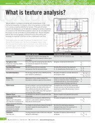
IV.EXAMPLESSome users may download programs into the <strong>YR</strong>-1 using the EZ-Yield software and then usethe instrument remotely without computer data acquisition, as discussed in Secion II. However,other users may wish to acquire data with the EZ-Yield software and a personal computer tographically analyze the sample material’s behavior. Examples are presented below.Figure IV-1 is a graph of Torque (%) vs. Time (seconds), and Figure IV-2 is a graph of stress(Pa) vs. strain (γ). Data is presented for very different materials: cream cheese, mayonnaise,pudding and ketchup. Experimentally determining an appropriate combination of spring,spindle and speed for testing each material ensures that the torque readings were within therecommend 10-100% on the torque scale. If a sample has a relatively low torque reading forthe yield (
Figure IV-2: Stress vs. Strain Graphs for Various Food ProductsBrookfield Engineering Labs., Inc. Page 30 <strong>Manual</strong> No. M/02-215
APPENDIX A - Spindle and Model CodesEach spindle has a two (2) digit code which is selected via the EZ-Yield software. The codeallows the <strong>YR</strong>-1 to calculate Yield Stress.The immersion mark selected affects the stress calculations. Ensure the selected immersion markreflects the mark in use.Each spindle has a Yield Multiplier Constant (YMC) for stress calculations and a SpindleMultiplier Constant (SMC) for calibration checks as shown in Table A1. Spindle dimensions arealso listed.Spindle Vane Length Vane DiameterSpindle Code YMC SMC inches cm inches cmV-71 71 0.5 2.62 2.708 6.878 1.354 3.439V-72 72 2.0 11.1 1.706 4.333 .853 2.167V-73 73 10.0 53.5 .998 2.535 .499 1.267Table A1Note: If secondary immersion mark is selected, the YMC value is doubled.Table A2 lists the model codes and spring torque constants (TK) for each Rheometer model.Model Code OnModel Tk <strong>YR</strong>-1 ScreenRV<strong>YR</strong>-1 1 RVHB<strong>YR</strong>-1 8 HB5HB<strong>YR</strong>-1 40 5HBTable A2The full scale Yield Stress range for any <strong>YR</strong>-1 model and spindle may be calculated usingthe equation:Full Scale Yield Stress Range (Pa) = TK x YMC x 10where:TK = <strong>YR</strong>-1 Torque Constant from Table A2YMC = Yield Multiplier Constant from Table A1Brookfield Engineering Labs., Inc. Page 31 <strong>Manual</strong> No. M/02-215
APPENDIX B - SpeedsPre-Shear Speeds (RPM)Range Increment0.01 to 0.09 0.010.1 to 5.0 0.16, 10, 12, 20, 30, N/A50, 60, 100, 200Zero Speeds (RPM)Range Increment0.01 to 0.09 0.010.1 to 5.0 0.1Run Speeds (RPM)Range Increment0.01 to 0.09 0.010.1 to 5.0 0.1Brookfield Engineering Labs., Inc. Page 32 <strong>Manual</strong> No. M/02-215
APPENDIX C - Calibration ProceduresThe torque sensing spiral spring in the <strong>YR</strong>-1 Rheometer is calibrated at Brookfield to be accuratewithin ±2% of full scale range of a certified master viscometer. When checking calibration in thefield with a vane spindle (spindle 71, 72, or 73) using the following procedures, an accuracy of±2% of full scale range can be expected.The accuracy of the <strong>YR</strong>-1 is verified using viscosity standard fluids which are available fromBrookfield Engineering Laboratories or your local Brookfield agent. Viscosity standards areNewtonian and, therefore, have the same viscosity regardless of spindle speed. Viscositystandards, calibrated at 25°C, are shown in Table C1 (Silicone Oils) and Table C2 (Mineral Oils).GENERAL PURPOSE SILICONE FLUIDSBEL Part No. Viscosity (cP) at 25°C5 cps 510 cps 1050 cps 50100 cps 100500 cps 5001,000 cps 1,0005,000 cps 5,00012,500 cps 12,50030,000 cps 30,00060,000 cps 60,000100,000 cps 100,000Table C1 - Silicone Viscosity Standard FluidsMINERAL OIL VISCOSITY STANDARD FLUIDSBEL Part No. Viscosity (cP) 25°CB31 31B210 210B750 750B1400 1,400B2000 2,000B11000 11,000B20000 20,000B80000 80,000B200000 200,000B420000 420,000Table C2 - Mineral Oil Viscosity Standard fluidsBrookfield Engineering Labs., Inc. Page 33 <strong>Manual</strong> No. M/02-215
Container size:Temperature:For Viscosity Standards < 30,000 cP, use a 600 ml Low Form GriffinBeaker having a working volume of 500 ml.For Viscosity Standards >/= 30,000 cP, use the fluid container.Inside Diameter: 3.25” (8.25 cm)Height:4.75” (12.1 cm)Note: Container may be larger, but may NOT be smaller!As stated on the fluid standard label (±) 0.1°CBrookfield Viscosity Standard Fluid General InformationWe recommend that Brookfield Viscosity Standard Fluids be replaced on an annual basis, oneyear from date of initial use. These fluids are pure silicone and are not subject to change overtime. However, exposure to outside contaminants through normal use requires replacement onan annual basis. Contamination may occur by the introduction of solvent, standard of differentviscosity or other foreign material.Viscosity Standard Fluids may be stored under normal laboratory conditions. Disposal shouldbe in accordance with state, local, and federal regulations as specified on the material safety datasheet.Brookfield Engineering Laboratories does not re-certify Viscosity Standard Fluids. We willissue duplicate copies of the Certificate of Calibration for any fluid within two years of purchasedate. Brookfield Viscosity Standard Fluids are reusable provided they are not contaminated.Normal practice for usage in a 600 ml beaker is to return the material from the beaker back intothe bottle. When using smaller volumes in accessories such as the Small Sample Adapter, ULAdapter, or Thermosel, the fluid is normally discarded.Calibration Check Procedure1) Shut off the rheometer.2) Place the viscosity standard fluid (in the proper container) into the water bath.3) Press and hold the and keys simultaneously while turning the rheometer power ON.Figure C1 appears on the rheometer display.<strong>RHEOMETER</strong> SETUPENTER TO STARTFigure C14) Press the ENTER key and Figure C2 appears on the rheometer display.CAL VERIFY?NO THEN ENTERFigure C2Using the or key, set the CAL VERIFY setting to YES, then press the ENTER key. FigureC3 appears on the rheometer display. Ensure the rheometer is level, and remove any attachedspindle before auto-zeroing.Brookfield Engineering Labs., Inc. Page 34 <strong>Manual</strong> No. M/02-215
REMOVE SPINDLEPRESS ANY KEYFigure C35) After pressing a key, Figure C4 is displayed with the text flashing.AUTOZEROING<strong>RHEOMETER</strong>Figure C4When the auto-zero is complete, Figure C5 appears on the rheometer display with OFFRPMflashing.CP 0.00 S71% 0.0 OFFRPMFigure C56) Attach the spindle to be used in the calibration check and lower it into the appropriateBrookfield Viscosity Standard Fluid.Note: Avoid trapping air bubbles beneath any surface of the spindle by first immersingthe spindle in the fluid at an angle, then connecting it to the rheometer.7) The viscosity standard fluid, together with the spindle, should be immersed in the bath for aminimum of one (1) hour, stirring the fluid periodically, prior to taking measurements.8) After one (1) hour, check the temperature of the viscosity standard fluid with an accuratethermometer.9) If the fluid is at test temperature (±0.1°C of the specified temperature, normally 25°C),measure the viscosity according to the following steps and record the reading.10) Use the and keys to select the speed to be used for the calibration check. Speeds between0.1 and 100 rpm are available for use in checking the calibration. Once a speed is selectedby pressing the ENTER key, the spindle rotates at this speed, and % Torque and a Viscosityvalue are displayed, and the S71 begins flashing.11) Use the and keys to select the spindle to be used for the calibration check. All standardBrookfield spindles in addition to any pre-programmed special spindles may be used to checkthe calibration of the instrument. Once a spindle is selected by pressing the ENTER key, theviscosity value is computed and displayed. Pressing the ener key toggles between the spindleand speed fields.Note: The spindle must rotate at least five (5) times before readings are taken.12) The viscosity reading should equal the cP value on the viscosity fluid standard to within thecombined accuracies of the Rheometer and the viscosity standard fluid as discussed in thefollowing section (Interpretation of Calibration Test Results).Brookfield Engineering Labs., Inc. Page 35 <strong>Manual</strong> No. M/02-215
13) When the calibration check is complete, switch off the rheometer or press the ESC key if youwish to Print Parameter RAM (see Appendix H – Fault Diagnosis and Troubleshooting).Interpretation of Calibation Test Results:When verifying the calibration of the <strong>YR</strong>-1 Rheometer, the instrument and viscosity standardfluid error must be combined to calculate the total allowable error.The <strong>YR</strong>-1 is accurate to ±2% of any full scale spindle/speed viscosity range for vane spindlesand ±1%of any full scale spindle/speed viscosity range for all other Brookfield spindles.Brookfield Viscosity standard Fluids are accurate to ±1% of their stated value.Example:Calculate the acceptable range of viscosity using the RV<strong>YR</strong>-1 Rheometer andV-71 spindle at 2 RPM; Brookfield Standard Fluid 12,500 with a viscosity of12,257 cP at 25°C:1) Calculate full scale viscosity range using the equation:Full Scale Viscosity Range [cP] = TK * SMC *10,000RPMWhere:TK = 1.0 from Table A2SMC = 2.62 from Table A1Full Scale Viscosity Range1 * 2.62 * 10,0002= 13,100 cPThe viscosity is accurate to ±262 cP (which is 2%of 13,100)2) The viscosity standard fluid is 12,257 cP. Its accuracy is ±1% of 12,257 or ±123 cP.3) Total allowable error is 262 + 123 cP = ±385 cP.4) Therefore, any viscosity reading between 11,872 and 12,642 cP indicates that the <strong>YR</strong>-1Rheometer is operating correctly. Any reading outside these limits may indicate a problem.Contact the Brookfield technical sales department or your local Brookfield dealerwith test results to determine the nature of the problem.Brookfield Engineering Labs., Inc. Page 36 <strong>Manual</strong> No. M/02-215
APPENDIX D - CalculationsThe following equations can be used to calculate the shear stress values after each packet of datais obtained from the <strong>YR</strong>-1:τ =TK x YMC x T10where:τ = Yield Stress (Pascals)TK = Model Torque Constant from Table A2 in Appendix AYMC = Yield Multiplier Constant from Table A1 in Appendix AT = % Torque readingThe following equations can be used to calculate the strain data after each packet of data isobtained from the <strong>YR</strong>-1:γ = θ M — (S x T)where:γ = Strain (rad)θ M = Angular rotation of motor shaft (rad)S = Radial Spring Factor (rad/% torque)T = % Torque reading (%)θ M= ω x t x2 π60where:θ M = Angular distance of motor shaft (rad)ω = Speed (rpm)t = time of test (seconds)where:S = θ cal x (2 π) x 0.01S = Radial spring factor (rad/%torque)θ cal = Spring windup angle (revolutions)Brookfield Engineering Labs., Inc. Page 37 <strong>Manual</strong> No. M/02-215
(Vθ cal= cal x t cal )60000where:θ cal = Spring windup angle (revolutions)V cal = Calibration speed (fixed at 0.1 rpm) (rpm)t cal = Calibration time (milliseconds)(time for 0% to 100% spring wind up)t cal=bixVx 100b calV calt cal = Calibration time (milliseconds)(time for 0% to 100% spring windupduring calibration)bi = Base increment (milliseconds)b cal = base increment calibration torque (%torque/base increment)V = Speed (rpm)V cal = Calibration speed (rpm)(fixed at 0.1 rpm)Brookfield Engineering Labs., Inc. Page 38 <strong>Manual</strong> No. M/02-215
APPENDIX E - Communications1. Serial (RS-232) Communications ParametersBaud Rate 9600Data Bits 8Stop Bits 1Parity NoneHandshakeNone2. RS-232 Output During The TestAll output that occurs immediately before and after the test is described in Sections 4.2 and4.3. That pre- and post- test output is sent out both the serial (RS-232) and parallel ports.When using the Brookfield Computer Cable (Brookfield part # DVP-80), the <strong>YR</strong>-1 willoutput a data string during the actual yield test run. This data is ONLY sent out to the RS-232 port for use with the EZ-Yield software.The following output is sent to the serial (RS-232) port at the end of every Base Incrementperiod:xxxxxx:yy.yy:ttt.t:zz.zzwhere the delimiter between all fields is a colon (:) character andxxxxxx = The Base Increment count in hexadecimal format, padded with leading zeroes.This is the time, in milliseconds that each reading was taken in the instrument.yy.yy = % Torque value. % Torque is output with a resolution 0.01% with a maximumof 99.99%.ttt.tzz.zz= Temperature in °C.= Delta Torque (%). This is the actual change in percent torque, measured from theprevious reading, calculated at the end of each Base Increment period.No ConnectionReceive Data (RxD)Transmit Data (TxD)No ConnectionSerial Ground123456789Analog GroundAnalog % Torque(Note 1)Analog Temperature(Note 2)No ConnectionNotes:1. This is a 0-1 volt d.c. output where 0 volts corresponds to 0% torqueand 1 volt corresponds to 100 % torque with a resolution of 1 millivolt(0.1%).2. This is a 0-4 volt d.c. output where 0 volts corresponds to -100°C and4 volts corresponds to +300°C with a resolution of 1 millivolt (0.1°C).Brookfield Engineering Labs., Inc. Page 39 <strong>Manual</strong> No. M/02-215
Analog Output:The analog outputs for temperature and % torque are accessed from the 9-pin connectorlocated on the rear panel of the <strong>YR</strong>-1. The pin connections are shown in Figure E1.Theoutput cable (Part No. DVP-96Y) connections are:Red Wire:Black Wire:White Wire:Green Wire:Temperature OutputTemperature Ground% Torque Output% Torque GroundNote:Please contact Brookfield Engineering Laboratories or your local dealer/distributor forpurchase of the DVP-96Y analog output cable.See Appendix D to use the data acquired during a test to perform the appropriate calculations.Brookfield Engineering Labs., Inc. Page 40 <strong>Manual</strong> No. M/02-215
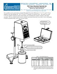
APPENDIX F - Model S Laboratory StandPARTS IDENTIFICATION & INSTRUCTIONSVS-35YMODEL SCLAMP ASSEMBLY761 811910<strong>BROOKFIELD</strong>LABORATORYVISCOMETER2345ITEM PART #12345678910VS-34VS-38VS-2VS-350S311824S06B502020032S34ZVS-35VS-40YVS-41YVS-29VS-29W14” UPRIGHT ROD18” UPRIGHT RODDESCRIPTIONBASELEVELING SCREWSCREW, 5/16-18 X 3/4 LG. SLOTTED PAN HD.LOCKWASHER, EXTERNAL TOOTH, 5/16 X 5/8 X 1/32CLAMPGEAR SCREW ASSEMBLYCLAMP SCREW ASSEMBLYTENSION INSERTBELLEVILLE SPRING WASHERQTY.1OPTIONAL12111111211 VS-28TENSION SCREW1Brookfield Engineering Labs., Inc. Page 41 <strong>Manual</strong> No. M/02-215
UnpackingCheck carefully to see that all the components are received with no concealed damage.1 Base, VS-2, with 2 Leveling Screws, VS-3, packed in a cardboard carton1 Upright Rod, VS-34, with attached Clamp Assembly, VS-35YAssembly (Refer to Figure F1)1. Remove the base assembly from the carton.2. Remove the screw and washer from the upright rod. Place the rod and clamp assembly into the holein the top of the base.Note:The “Front” designation on the clamp assembly should face theopening of the legs, i.e., parallel to the leveling feet.3. Rotate the rod/clamp assembly slightly until the slot on the bottom of the rod intersects the pinlocated in the base.4. While holding the rod and base together, insert the slotted screw and washer as shown and tightensecurely.<strong>YR</strong>-1 Rheometer MountingInsert the <strong>YR</strong>-1 Rheometer mounting rod into the hole (with the cut-away slot) in the clamp assembly.Adjust the instrument level until the bubble is centered from right to left and tighten the clamp knob(clockwise). Use the leveling screws to “fine” adjust the viscometer level. Note: If the Rheometercannot be leveled, check to insure that the rod is installed with the gear rack facing forward.Note:If the clamp is taken off the upright rod, the tension insert (Part No. VS-29) must beproperly aligned for the clamp to fit back onto the upright rod. When the tension insert(Part No. VS-29) is inserted, its slot must be in the vertical position parallel to theupright rod. If the slot is not in the correct position, the clamp will not slide down overthe upright rod. Use a small screwdriver or pencil to move it into the correct position.The VS-29W Belleville spring washers must face each other as illustrated. Adjust theVS-28 tension screw so that the clamp assembly is not loose on the upright rod.CAUTION: Do not tighten the clamp knob unless the viscometer mounting rod isinserted in the clamp assembly.Center the <strong>YR</strong>-1 relative to the stand base and retighten the jam nut as required. Referring to theRheometer bubble level, adjust the leveling screws until the instrument is level.Brookfield Engineering Labs., Inc. Page 42 <strong>Manual</strong> No. M/02-215
APPENDIX G - DVE-50 Probe ClipProbe Clip DVE-50 is supplied with all model <strong>YR</strong>-1 Rheometers. It is used to attach the RTDtemperature probe to low form Griffin beaker. Figure G1 is a view of the Probe Clip, showing thehole into which the RTD probe is inserted. When inserting the RTD probe into the Probe Clip, theupper part of the Clip is compressed by squeezing the points shown in Figure G1.RTD ProbeHoleSqueeze Here wheninstalling RTDTemperature ProbeFigure G1Figure G2 shows the probe clip monted in a 600 ml low form Griffin beaker.Note: The RTD probe must be parallel to the beaker wall so as not to interfere with the yield measurement.RTD Temperature Probe600mlUSA500ml400300DVE–50Probe ClipNo.14000200100600 ml Low FormGriffin BeakerFigure G2Brookfield Engineering Labs., Inc. Page 43 <strong>Manual</strong> No. M/02-215
APPENDIX H - Fault Diagnosis and TroubleshootingListed are some of the more common problems that you may encounter while using your <strong>YR</strong>-1Rheometer.❏ Spindle Does Not Rotate✓ Make sure the rheometer is plugged in.✓ Check the voltage rating on your rheometer (115, 220V); it must match the AC supply voltage.✓ Make sure the motor is ON and the desired rpm is selected.❏ Spindle Wobbles When Rotating or Looks Bent✓ Make sure the spindle is tightened securely to the rheometer coupling.✓ Check the straightness of spindle vanes; replace spindle if bent or warped.✓ Inspect rheometer coupling and spindle coupling mating areas and threads for dirt; cleanthreads on spindle coupling with a 3/56 left-hand tap.✓ Inspect threads for wear; if the threads are worn, the unit needs service (see Appendex I).Check to see if spindles rotate eccentrically or wobble. There is an allowable runout of 1/32-inch in each direction (1/16-inch total) when measured from the bottom of the spindle rotatingin air.✓ Check to see if the rheometer coupling appears bent; if so, the unit is in need of service (seeAppendix I, “How to Return Your Rheometer”).If you continue to experience problems with your rheometer, follow this troubleshooting section tohelp isolate potential problems.❏ Perform an Oscillation Check✓ Press and hold the and arrow keys simultaneously while turning the rheometer powerON. When prompted with CAL VERIFICATION on the display, use the arrow keysto select YES, then press the ENTER key. Ensure no spindle is attached before Autozeroing.✓ With the rheometer set to zero (0) rpm, gently push up on the rheometer coupling.✓ Turn the coupling until the display % torque reads 10-15.✓ Gently let go of the coupling.✓ Watch the display; you should see the torque value return to 0.0 (+/- 0.1).If the digital display does not return to ZERO, the unit is in need of service (see Appendix I, “Howto Return Your Rheometer”).Brookfield Engineering Labs., Inc. Page 44 <strong>Manual</strong> No. M/02-215
❏ Inaccurate Readings✓ Verify spindle, speed and model selection.✓ Verify that % Torque readings are greater than or equal to 10%.✓ Verify test parameters: Yield Test Parameters, container, volume and method. Refer toAppendix C, “Variables in Yield Measurements”.✓ Perform a calibration check; follow the instructions in Appendix B, “Calibration Procedures”.✓ Verify tolerances are calculated correctly.If the unit is found to be out of tolerance, the unit may be in need of service. See Appendix I fordetails on “How to Return Your Rheometer”.❏ Rheometer Will Not Return to Zero✓ Rheometer is not level• Check with spindle out of the sample• Adjust the laboratory stand✓ Pivot point or jewel bearing faulty• Perform calibration check. See Appendix C, “Calibration Procedures”.• Contact Brookfield Engineering Laboratories, Inc. or your Brookfield dealer for repair❏ Display Reading Will Not Stabilize✓ Rheometer is not level• Check with spindle out of the sample• Adjust the laboratory stand✓ Special characteristic of sample fluid. There is no problem with the rheometer.✓ Check for erratic spindle rotation.• Verify power supply• Contact Brookfield Engineering Laboratories, Inc. or your Brookfield dealer for repair✓ Bent spindle or spindle coupling.• Contact Brookfield Engineering Laboratories, Inc. or your Brookfield dealer for repair✓ Temperature fluctuation in sample fluid• Use temperature bath control.Brookfield Engineering Labs., Inc. Page 45 <strong>Manual</strong> No. M/02-215
❏ No Recorder Response✓ Be Sure the rheometer is not at ZERO reading.✓ Be sure the recorder is ON and not on STANDBY.✓ Verify the range settings.✓ Check cable leads for clean connection.❏ Recorder Pen Moves in Wrong Direction✓ Output polarity reversed• Reverse leads❏ Rheometer Will Not Communicate with PC✓ Check the comm port setting and make sure the correct port on the PC is being utilized.✓ Ensure that the rheometer has the appropriate communications cable (Communications)connected to it and that the opposite end of the cable is connected to a valid COM (serial)port on the host PC).✓ Ensure that the rheometer is powered ON.✓ Ensure that the appropriate COM port is selected on the Main Toolbar of the EZ-Yield software.✓ If there is still erratic or no communication, check the following:• Click the START button. Select “Settings” then “Control Panel”. Double click the “System”icon. Select the “Device Manager” tab. Select “Ports”, highlight the COM pot in useand click the “Properties” button (or double-click the COM port in use). Click “PortSettings” then “Advanced”.• Ensure the check box labeled “Use FIFO buffers (requires 16550 compatible UART)” ischecked. Ensure that the sliders for the “Receive Buffer” and the “Transmit Buffer” areboth set all the way to the left (Low). Click the OK buttons to accept the changes and getback to the desktop.• If there is still a communication problem, follow the above procedure, but this time, uncheckthe box labeled “Use FIFO buffers (requires 16550 compatible UART)”. Again,check the OK buttons to accept the changes.✓ Check the interconnecting cable for proper installation.If the above do not rectify the problem, perform the following:✓ Shut off the rheometer.✓ Attach a printer to the parallel port.✓ Press and hold the and keys simultaneously while turning the rheometer power ON.Figure H1 appears on the rheometer display:<strong>RHEOMETER</strong> SETUPENTER TO STARTFigure H1Brookfield Engineering Labs., Inc. Page 46 <strong>Manual</strong> No. M/02-215
Press the ENTER key and Figure H2 appears.CAL VERIFY?NO THEN ENTERFigure H2Ensure NO is displayed then press the ENTER key and Figure H3 appears.PRINT PARAM RAM?NO THEN ENTERFigure H3Using the and key, scroll to YES and press the ENTER key. Figure H4 appears.READY PRINTERENTER TO STARTFigure H4Press the ENTER key. Information similar to Figure H5 is printed on the attached printer.Printer PortParallelSpecial Spindle AA SMC 0000.000Special Spindle AA SRC 00.000Special Spindle BB SMC 0000.000Special Spindle BB SRC 00.000Special Spindle CC SMC 0000.000Special Spindle CC SRC 00.000Special Spindle DD SMC 0000.000Special Spindle DD SRC 00.000Special Spindle EE SMC 0000.000Special Spindle EE SRC 00.000Viscometer Model5HBRaw Temps3A1E 039ETorque ScaleD324Yield Constant 125158.7Figure H5✓ Contact Brookfield or our authorized dealer to review the information printed in the last step.✓ Figure H6 next apears on the rheometer display. Turn the rheometer power OFF.SETUP COMPLETETURN POWER OFFFigure H6Brookfield Engineering Labs., Inc. Page 47 <strong>Manual</strong> No. M/02-215
APPENDIX I - Warranty Repair and ServiceWarrantyBrookfield Rheometers are guaranteed for one year from date of purchase against defects in materialsand workmanship. They are certified against primary viscosity standards traceable to the NationalInstitute of Standards and Technology (NIST). The Rheometer must be returned to BrookfieldEngineering Laboratories, Inc. or the Brookfield dealer from whom it was purchased for no chargewarranty service. Transportation is at the purchaser’s expense. The Rheometer should be shipped in itscarrying case together with all spindles originally provided with the instrument.For repair or service in the United States, return to:Brookfield Engineering Laboratories, Inc.11 Commerce BoulevardMiddleboro, MA 02346 U.S.A.Telephone: (508) 946-6200 FAX: (508) 946-6262http://www.brookfieldengineering.comFor repair or service outside the United States consult Brookfield Engineering Laboratories, Inc.or the dealer from whom you purchased the instrument.For repair or service in the United Kingdom return to:Brookfield Viscometers Limited1 Whitehall EstateFlex MeadowPinnacles WestHarlow, Essex CM19 5TJ, United KingdomTelephone: (44) 27/945 1774 FAX: (44) 27/945 1775For repair or service in Germany return to:Brookfield Engineering Laboratories Vertriebs GmbHHauptstrasse 18D-73547 Lorch, GermanyTelephone: (49) 7172/927100 FAX: (49) 7172/927105Brookfield Engineering Labs., Inc. Page 48 <strong>Manual</strong> No. M/02-215
Packaging <strong>Instructions</strong> to Return a Rheometer for Repair or Calibration❏ Remove and return all spindles (properly packed for shipping).❏ Clean excess testing material off the instrument.❏ Include MSDS sheets for all materials tested with this instrument.❏ Support pointer shaft with white, nylon shipping cap, as shown in Figure I1, or with whiteplastic shipping cap originally supplied with instrument.❏ Pack the instrument in its original case. Cases are available for immediate shipment fromBrookfield. If the case is not available, take care to wrap the instrument with enough materialto support it. Avoid using foam peanuts or shredded paper.❏ DO NOT send the laboratory stand unless there is a problem with the upright rod, clamp orbase. If there is a problem with the stand, remove the upright rod from the base and individuallywrap each item to avoid contact with the instrument. Do not put lab stand in rheometer carryingcase.❏ Fill out a copy of the Rheometer Information Sheet (on the following page) with as muchinformation as possible to help expedite your service. If you do not use this form, pleaseinclude a memo indicating the type of problem you are experiencing or the service you needperformed. Please also include a purchase order number for us to bill against.❏ Package the instrument and related items in a strong box for shipping. Mark the outside of thebox with handling instructions.Example: "Handle with Care" or"Fragile - Delicate Instrument"Figure I1Brookfield Engineering Labs., Inc. Page 49 <strong>Manual</strong> No. M/02-215
Providing us with the following information will help us to service your equipment more quickly andefficiently. Please photocopy, fill out and return a copy of this form with your instrument.Brookfield recommends that all viscometers be returned for annual calibration to ensure that yourequipment continues to provide the same accuracy you have come to expect from Brookfield products.1<strong>RHEOMETER</strong> INFORMATIONSerial Number: _______________________Date:_______________________Model: _____________________2COMPANY INFORMATIONCompany: _________________________ Primary User: ________________________Telephone: ________________________ Fax: ________________________________P.O. Number: ______________________ (to cover repair and shipping)Billing Address: ____________________ Shipping Address: ______________________________________________________ ____________________________________________________________________ ____________________________________________________________________ ___________________________________Return Shipment <strong>Instructions</strong>: UPS ground ❏ UPS Next Day ❏ UPS 2nd Day ❏Federal Express ❏ _______________________________(Federal Express Account Number required)3 SERVICE INFORMATION<strong>Operating</strong> Conditions (Spindle; Speed; Temp. Control; Temperature of Sample): _______________________________________________________________________________________________________________________________________________________________Did you contacting Brookfield before returning this instrument? Y❏ N❏If yes, whom did you contact? ________________________________________________Description/Symptoms of Present Problem/Malfunction (please list all):___________________________________________________________________________________________________________________________________________________________________________________________________________________________Time Since Last Serviced (if known): ______ Before & After Calibration Check? Y❏ N❏Other Comments: _______________________________________________________________________________________________________________________________________________________________________________________________________STEPS: ❏ Return the rheometer to the attention of the Repair Department at the address above.❏ Package the rheometer for shipment, as outlined on the preceeding page.❏ Include a purchase order or purchase order number with this form.Brookfield Engineering Labs., Inc. Page 50 <strong>Manual</strong> No. M/02-215