environment impact evaluation of a new type continuous mixing
environment impact evaluation of a new type continuous mixing
environment impact evaluation of a new type continuous mixing

You also want an ePaper? Increase the reach of your titles
YUMPU automatically turns print PDFs into web optimized ePapers that Google loves.
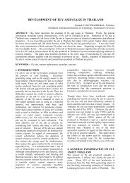
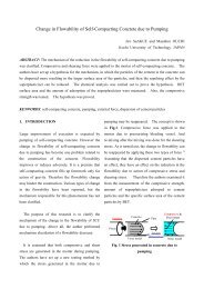
Inlet 2(2 1 )layersOutlet Inlet 4(2 2 )layersOutlet Inlet 8(2 3 )Outlet layersnn unitsMY-mixer2 nlayersVerticalInletHorizontaloutletFlow<strong>of</strong> MaterialsKneadingProcessLappingProcessFig.3 Continuous concrete mixer “MY-mixer” and its <strong>mixing</strong> theory.and <strong>continuous</strong> <strong>mixing</strong> plant are estimated anddiscussed. In these estimations, electricityconsumption and CO 2 discharge are calculated as<strong>environment</strong>al <strong>impact</strong>s. First the total electric power<strong>of</strong> each equipment, namely necessary power per hour(kW) for operating the plant, is calculated. And thencalculated power divided by production capacity <strong>of</strong>the plant is power consumption per unit volume <strong>of</strong>product (kWh/m 3 ), and the power consumptionmultiplied by <strong>environment</strong>al <strong>impact</strong> rate <strong>of</strong> CO 2(kg/kWh) is CO 2 discharge per unit volume <strong>of</strong>product (kg/m 3 ). In these calculations, the requiredpower for each equipment is referred to reference 6.And <strong>environment</strong>al <strong>impact</strong> rate <strong>of</strong> CO 2 is defined as0.371kg/kWh referred to the investigating result byconcrete committee <strong>of</strong> Japan society <strong>of</strong> civilengineers (Reference 1).4. ESTIMATION RESULTS4.1 Concrete plantFig.4 shows the outline <strong>of</strong> batch <strong>mixing</strong> plant.This plant equips 2m 3 pug mill <strong>type</strong> forced mixer.Since it is necessary to mix dam concrete composed<strong>of</strong> large size particle <strong>of</strong> aggregate, the cycle time <strong>of</strong><strong>mixing</strong> is set to 90 minutes, and thus its <strong>mixing</strong>capacity is 80m 3 per hour. On its manufactureprocesses, first the materials are transported to themain tower <strong>of</strong> plant by each feeder and beltconveyers, and then measuring <strong>of</strong> materials and<strong>mixing</strong> <strong>of</strong> concrete are conducted repeatedly. Fig.6shows the outline <strong>of</strong> continues <strong>mixing</strong> plant. Thisplant equips a <strong>continuous</strong> mortar mixer and a<strong>continuous</strong> concrete mixer “MY-mixer”. Thecapacity <strong>of</strong> continues mortar mixer is 70m 3 /h and thecapacity <strong>of</strong> MY-mixer is 150m 3 /h. In its manufactureprocesses, first the course aggregate are fed to thebelt conveyer 1 by each feeder <strong>continuous</strong>ly. At thesame time, powder materials, fine aggregate andwater are fed into <strong>continuous</strong> mortar mixer andmixed <strong>continuous</strong>ly, and then the mixed mortal is fedon the course aggregate on belt conveyer 1. And theall <strong>of</strong> materials on belt conveyer 1 are transported tothe top <strong>of</strong> the MY-mixer and dropped into the inside<strong>of</strong> MY-mixer, and then concrete <strong>mixing</strong> is conducted<strong>continuous</strong>ly at the inside <strong>of</strong> MY-mixer only bygravity force. The details <strong>of</strong> structure andequipments <strong>of</strong> their two plants are given in table 1.