''out of wall/partition'' fire damper and combination fire/smoke - NCA ...
''out of wall/partition'' fire damper and combination fire/smoke - NCA ...
''out of wall/partition'' fire damper and combination fire/smoke - NCA ...

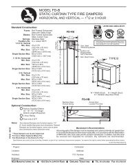
Create successful ePaper yourself
Turn your PDF publications into a flip-book with our unique Google optimized e-Paper software.
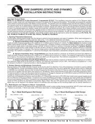
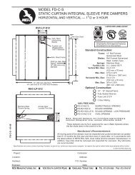
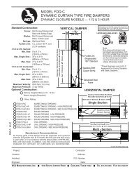
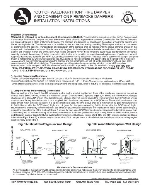
Fig. 2: Metal or Wood Stud WallSection A-A2.5" Min. Stud16" 16"Ceiling RunnerNote: Gypsum panels screwed to all studs <strong>and</strong>runner flanges, 12” oc maximumsurrounding opening. All fasteners areto be UL approved per UL design.Screws2.5" Min. RunnerARunner90 BendDouble Stud NotRequired on Penetrations36" x 36"Or SmallerASee UL Directory forMaximum AllowableOpening Size PerFire Damper ModelMax. 48"12"2 #10 SheetMetal ScrewsMax. 42"2"24" O.C.Max.2"FloorRunner3. Methods <strong>of</strong> Securing Damper in Opening:a. Grille Mount Method: In this method NO angles are used to secure the <strong>damper</strong> in the opening. This method is approved for use inUL approved concrete/masonry partitions <strong>and</strong> steel stud/gypsum <strong>wall</strong>s. This method uses a minimum 3 /4” (19mm) flange is on one end<strong>of</strong> the sleeve. The <strong>damper</strong>/sleeve assembly is placed in the opening so that the flange rest flush up to the partition, then the fastenersare placed through the sleeve into the partition (see Fig. 6). No Angle Method is approved for 1 1 /2 hour <strong>damper</strong>s only, vertical <strong>and</strong>horizontal (flange on top side only) orientations, <strong>and</strong> the maximum size shall be 42” (1067mm) wide by 48” (1219mm) high up to themaximum multi-section UL approved <strong>damper</strong> size (see Underwriter’s Laboratories Listings for maximum assembly sizes). The sleeveflange shall be a minimum <strong>of</strong> 3 /4” (19mm) high by 20 gauge steel. If a flange/angle is added, it shall be a minimum <strong>of</strong> 1” x 1” (25mm x25mm) by 18 gauge steel <strong>and</strong> fastened with #10 (M5) bolts or screws, 1 /2” (13mm) welds, or 3/16” (5mm) rivets to the sleeve, at amaximum spacing <strong>of</strong> 6” (152mm) o.c., not more than 2” (51mm) from each end with a minimum <strong>of</strong> two fasteners per side. The sleeveis to be fastened to the <strong>fire</strong> partition: in concrete/ masonry partitions with #10 self-tapping concrete anchors or concrete screwson 6” (152mm) centers <strong>and</strong> must engage the <strong>fire</strong> partition a minimum <strong>of</strong> 1 1 /2” 38mm); in stud/gypsum partitionswith #10 (M5) screws long enough to penetrate the J-Runners <strong>and</strong> E-Stud by a minimum <strong>of</strong> 3/8” (10mm). Use a minimum <strong>of</strong> tw<strong>of</strong>asteners per side. The sleeve flange can be placed in front <strong>of</strong> or behind the dry<strong>wall</strong> attaching directly to the steel studs or masonry.Be sure to not stretch the <strong>damper</strong> when securing it into the partition. Stretching the <strong>damper</strong> can cause it to bind <strong>and</strong> prevent itfrom operating properly. <strong>NCA</strong>’s Frame Retaining Angles (FRA) can be used in place <strong>of</strong> the angle mentioned above. See Note 1for information on clearances. See Fig. 6 for detailed drawings <strong>of</strong> installations.b. Continuous Duct Method: In this method one (1) set <strong>of</strong> angles are used to secure the <strong>damper</strong> in the opening. This method isapproved for use in UL approved concrete/masonry partitions <strong>and</strong> steel stud/gypsum <strong>wall</strong>s. Only one side <strong>of</strong> the <strong>fire</strong> partition will havethe angles installed (see Fig. 7). One Angle Method is approved for 1 1 / 2 hour <strong>damper</strong>s only, vertical <strong>and</strong> horizontal(angles on top side only) orientations, <strong>and</strong> the maximum size shall be 42” wide x 48” high <strong>and</strong> up to the maximum multi-sectionUL approved <strong>damper</strong> size (see Underwriter’s Laboratories Listings for maximum assembly sizes). Angle shall be a minimum <strong>of</strong> 11 1 /2” x 1 1 / 2” (37mmx37mm) by 16 gauge. Angles are to be fastened to the sleeve on 6” centers with #10 (M5) sheet metal screws,3/16” (5mm) steel pop rivets, 1 / 2” (13mm) tack welds, or 1 /4 ” (6mm) diameter nut <strong>and</strong> bolts with not more than 2” (51mm) from eachend with a minimum <strong>of</strong> two connections on each side/leg top <strong>and</strong> bottom. The angles are also to be fastened to the <strong>fire</strong> partition:in concrete/masonry partitions with #10 (M5) self-tapping concrete anchors or concrete screws on 6” (152mm) centers <strong>and</strong> mustengage the <strong>fire</strong> partition a minimum <strong>of</strong> 1 1 / 2 ” (38mm); in stud/gypsum partitions with #10 (M5) screws long enough to penetrate theJ-Runners <strong>and</strong> E-Stud by a minimum <strong>of</strong> 3/8” (10mm). Use a minimum <strong>of</strong> two fasteners per side. The angles are to overlap the partitiona minimum <strong>of</strong> 1” (25mm). These angles may be <strong>of</strong> a unit type construction <strong>and</strong> may or may not be fastened to each other at the corners.When the duct work terminates at the <strong>damper</strong> or installation prohibits angles from turning out away from the <strong>wall</strong>, the retaining angleshall be reversed (leg turned into the opening) providing the size <strong>of</strong> the opening is increased by an amount equal to twice the combinedthickness <strong>of</strong> the angle <strong>and</strong> the height <strong>of</strong> the screw or bolt head to maintain expansion clearances. Angles can be placed in front <strong>of</strong> orbehind the dry<strong>wall</strong> attaching directly to the steel studs or masonry. <strong>NCA</strong>’s Frame Retaining Angles (FRA) can be used in place <strong>of</strong>the angle mentioned above. See Note 1 for information on clearances.See Fig. 7 for detailed drawings <strong>of</strong> installations.4. Actuator Connections (if applicable):Electrical <strong>and</strong>/or pneumatic connections to <strong>damper</strong> actuators (if provided) should be made in accordance with wiring <strong>and</strong> piping diagramsdeveloped in compliance with applicable codes, ordinances <strong>and</strong> regulations. Be sure to check actuator for proper voltage <strong>and</strong> currentdraw. Tampering with the actuator’s installation or connecting the actuator to an improper voltage <strong>and</strong> current may void the warranty.January 2009 – FD/FSD-OW Gen. InstallPAGE 2 OF 4<strong>NCA</strong> MANUFACTURING, INC. 1036 SOUTH JUPITER ROAD GARLAND, TEXAS 75042 TEL. 972-276-5002 FAX 972-276-6747
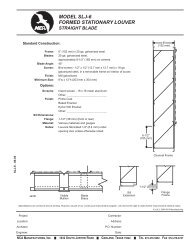
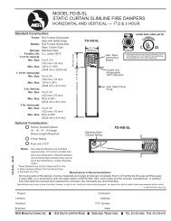
3/4" Flange(Typ. 4 Sides)20 Ga. St.GrilleGrille MountWith "-OW" or "-FA" DamperUL ApprovedWall DesignMetal Studs#10 Sheet MetalScrews, 8" oc.Masonry Walls#10 Self-TappingConcrete Anchors6" ocActuatorThermal InsulationFactory Supplied(Typ. 3 Sides)*Fire/SmokeOr CurtainFire DamperFig. 6 – Grille Mount (No Angle) MethodGrille Mount 'Out'Steel/GypsumUL ApprovedWall Design3/4" Flange(Typ. 4 Sides)20 Ga. St.#10 Sheet MetalScrews, 6" oc.GypsumFactory InstalledInsulation(Typ. 3 Sides)*Fire/Smoke Damperor Curtain Fire DamperUL ApprovedWall DesignMasonryUL ApprovedMasonry Wall DesignGrille Mount 'In'Stud/Gypsum3/4" Flange(Typ. 4 Sides)20 Ga. St.#10 Sheet MetalScrews, 6" oc.Grille MountGypsumFactory InstalledInsulation(Typ. 3 Sides)*Fire/Smoke Damperor Curtain Fire DamperFactory InstalledInsulation(Typ. 3 Sides)*RetainingAngleSteel Sleeve6" MaxStud/Gypsum or MasonryAs Found in the UL FileResistance DirectoryFire WallSleeveFactory InstalledInsulation(Typ. 3 sides)*Fire/SmokeDamperFig. 7 – Continuous Duct (One Angle) MethodFastenersRetainingAngleFastenersFire Rated PartitionSleeve5" Max.Factory InstalledInsulation(Typ. 3 Sides)*3/4" Flange(Typ. 4 Sides)20 Ga. St.Masonry Walls#10 Self-TappingConcrete Anchors,6" oc.Fire/Smoke Damperor Curtain Fire DamperTyp.Sides2"3.5SleeveFastenersActuatorStud/GypsumWallFire/Smoke Damperor Curtain Fire DamperRetaining AngleMin. 1" OverlapCombination Fire <strong>and</strong> Smoke DamperActuatorStud/GypsumWallFastenersRetainingAngleUL ApprovedWall DesignFactory InstalledInsulation(Typ. 3 Sides)*MasonryWallFastenersRetainingAngleUL ApprovedWall DesignFactory InstalledInsulation(Typ. 3 Sides)*SleeveFastenersRetainingAngleFactory InstalledInsulation(Typ. 3 Sides)*SleeveDamperDamperSleeve*Typical Three (3) sides when mounted vertically as shown,or typical Four (4) sides when mounted horizontally.Fire/Smoke Damperor Curtain Fire DamperThe curtain <strong>and</strong> airfoil blade type <strong>fire</strong> <strong>damper</strong> installation is the same as the 3-V blade type <strong>fire</strong> <strong>damper</strong> shown.This instruction sheet has been reviewed <strong>and</strong> accepted by Underwriters Laboratories.January 2009 – FD/FSD-OW Gen. InstallPAGE 4 OF 4<strong>NCA</strong> MANUFACTURING, INC. 1036 SOUTH JUPITER ROAD GARLAND, TEXAS 75042 TEL. 972-276-5002 FAX 972-276-6747© 2004 <strong>NCA</strong> Manufacturing