An Iterative Algorithm and Low Complexity Hardware Architecture ...
An Iterative Algorithm and Low Complexity Hardware Architecture ...
An Iterative Algorithm and Low Complexity Hardware Architecture ...

Create successful ePaper yourself
Turn your PDF publications into a flip-book with our unique Google optimized e-Paper software.
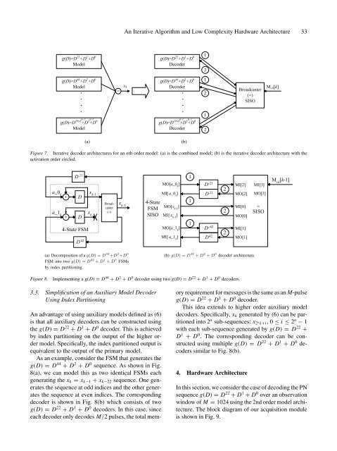
<strong>An</strong> <strong>Iterative</strong> <strong>Algorithm</strong> <strong>and</strong> <strong>Low</strong> <strong>Complexity</strong> <strong>Hardware</strong> <strong>Architecture</strong> 33g(D)=D 22 +D 1 +D 0Modelg(D)=D 44 +D 2 +D 0Model=g(D)=D 22 +D 1 +D 0Decoderg(D)=D 44 +D 2 +D 0x k Decoder1212Broadcaster(=)SISOM ch [k]g(D)=D 22x2 n-1+D 2 n-1+D 0Modelg(D)=D 22x2 n-1+D 2 n-1+D 0Decoder12(a)(b)Figure 7. <strong>Iterative</strong> decoder architectures for an nth order model: (a) is the combined model; (b) is the iterative decoder architecture with theactivation order circled.D 21 x kx k-1MO[a_0 k]1D -21 2MI[2]MI[3]M ch[k-1]a_0 k+ Da_1 k+ D4-State FSMD 42Broadcaster(=)x k-14-StateFSMSISOMI[ a_0 k] D 21MO[x k-1]MI[ x k-1]MO[a_1 k]MI[ a_1 k]11D -42D 4222MO[2]MI[0]MO[0]MI[1]MO[1]MO[3]=SISO(a) Decomposition of a g(D) = D 44 +D 2 +D 0FSM into two g(D) = D 22 + D 1 + D 0 FSMsby index partitioning.(b) g(D) = D 44 + D 2 + D 0 decoder architecture.Figure 8.Implementing a g(D) = D 44 + D 2 + D 0 decoder using two g(D) = D 22 + D 1 + D 0 decoders.3.3. Simplification of an Auxiliary Model DecoderUsing Index Partitioning<strong>An</strong> advantage of using auxiliary models defined as (6)is that all auxiliary decoders can be constructed usingthe g(D) = D 22 + D 1 + D 0 decoder. This is achievedby index partitioning on the output of the higher ordermodel. Specifically, the index partitioned output isequivalent to the output of the primary model.As an example, consider the FSM that generates theg(D) = D 44 + D 2 + D 0 sequence. As shown in Fig.8(a), we can model this as two identical FSMs eachgenerating the x k = x k−1 + x k−22 sequence. One generatesthe sequence at odd indices <strong>and</strong> the other generatesthe sequence at even indices. The correspondingdecoder is shown in Fig. 8(b) which consists of twog(D) = D 22 + D 1 + D 0 decoders. In this case, sinceeach decoder only decodes M/2 pulses, the total memoryrequirement for messages is the same as an M-pulseg(D) = D 22 + D 1 + D 0 decoder.This idea extends to higher order auxiliary modeldecoders. Specifically, x k generated by (6) can be partitionedinto 2 n sub-sequences: x 2 n k+i, 0 ≤ i ≤ 2 n − 1with each sub-sequence generated by g(D) = D 22 +D 1 + D 0 . The corresponding decoder can be constructedusing multiple g(D) = D 22 + D 1 + D 0 decoderssimilar to Fig. 8(b).4. <strong>Hardware</strong> <strong>Architecture</strong>In this section, we consider the case of decoding the PNsequence g(D) = D 22 + D 1 + D 0 over an observationwindow of M = 1024 using the 2nd order model architecture.The block diagram of our acquisition moduleis shown in Fig. 9.