1996-2002 Dodge Viper GTS Cat-Back Exhaust System Installation ...
1996-2002 Dodge Viper GTS Cat-Back Exhaust System Installation ...
1996-2002 Dodge Viper GTS Cat-Back Exhaust System Installation ...

Create successful ePaper yourself
Turn your PDF publications into a flip-book with our unique Google optimized e-Paper software.
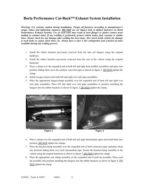
Borla Performance <strong>Cat</strong>-<strong>Back</strong> <strong>Exhaust</strong> <strong>System</strong> <strong>Installation</strong>Warning: Use extreme caution during installation. Torque all fasteners according to manufacturer’storque values and tightening sequence. DO NOT use air impact tools to tighten fasteners on BorlaPerformance <strong>Exhaust</strong> <strong>System</strong>s. Use of such tools may result in bent flanges or gasket contact areasleading to exhaust leaks. If any welding is performed, protect vehicle brake, fuel, vacuum or similarlines. Always check for any damage after welding has been done. Also check inside vehicle for damageto such items as carpet, inner liner, etc. Always have a class C fire extinguisher and a bucket of wateravailable during any welding process.1. Install the rubber brackets previously removed from the side rail hangers using the originalhardware.2. Install the rubber brackets previously removed from the rear of the vehicle using the originalhardware.3. Place a clamp over the expanded end of both left and right front muffler assemblies and place intoposition sliding them on to the catalytic converter pipe as shown in figure 1. DO NOT tighten theclamp.4. Install oxygen sensors into both left and right over axle pipe assemblies.5. Place the appropriate hanger/clamp assembly over the expanded end of both left and right overaxle pipe assemblies. Place left and right over axle pipe assemblies in position installing thehangers into the rubber brackets as shown in figure 2. DO NOT tighten the clamp.Figure 1 Figure 26. Place a clamp over the expanded end of both left and right intermediate pipes and install them intoposition. DO NOT tighten the clamps.7. Place the bracket/clamp assembly over the expanded end of both connector pipes and place theminto position sliding them over each intermediate pipe. Secure the bracket/clamp assembly to thevehicle using the original hardware as shown in figure 3. DO NOT tighten the clamp.8. Place the appropriate rear clamp assembly on the expanded end of each tip assembly. Place eachtip assembly into position installing the hangers into the rubber brackets as shown in figure 4. DONOT tighten the clamp.9/20/02 Form A-35037 14663 4