3550,3551 - Pro-Flo EFI for Big Block Chevy.qxp - Edelbrock
3550,3551 - Pro-Flo EFI for Big Block Chevy.qxp - Edelbrock
3550,3551 - Pro-Flo EFI for Big Block Chevy.qxp - Edelbrock

You also want an ePaper? Increase the reach of your titles
YUMPU automatically turns print PDFs into web optimized ePapers that Google loves.
®TABLE OF CONTENTSPart #<strong>3550</strong> and #<strong>3551</strong>Introduction.................................................................................................................................................1Components................................................................................................................................................2Preliminaries ...........................................................................................................................................3-5Fuel System ............................................................................................................................................6-9Induction System.................................................................................................................................10-12Sensors ...............................................................................................................................................13-15O 2 Sensor Installation................................................................................................................................15Main System Harness..........................................................................................................................16-20Ignition System................................................................................................................................... 21-25Other Applications.................................................................................................................................... 26System Start-Up ..................................................................................................................................26-29Electronic Engine Management .................................................................................................................30<strong>Pro</strong>-<strong>Flo</strong> Quick Tuning Guide.......................................................................................................................31Calibration Module <strong>Flo</strong>wchart....................................................................................................................32Parts and Part Numbers.......................................................................................................................33-34Service & Warranty ...................................................................................................................................35INTRODUCTIONThank you <strong>for</strong> selecting the <strong>Edelbrock</strong> <strong>Pro</strong>-<strong>Flo</strong> Fuel Injection System. This Multi-Point Fuel Injection System has been designed <strong>for</strong> 454 c.i.d. bigblockChevrolet engines, and is designed to provide excellent per<strong>for</strong>mance, fuel economy, and maintenance-free operation. Installation of the<strong>Edelbrock</strong>/ <strong>Pro</strong>-<strong>Flo</strong> Fuel Injection System involves modifications to the fuel system, ignition system, induction system, and possibly the valve train.Although there are steps that must take place be<strong>for</strong>e others, the modifications do not necessarily have to be per<strong>for</strong>med in a particular order.Each modification is described in a separate section in this manual. Please study these instructions carefully be<strong>for</strong>e beginning installation of anypart of the <strong>Pro</strong>-<strong>Flo</strong> system.Calibration Chips:Important Notice: The <strong>Edelbrock</strong> <strong>Pro</strong>-<strong>Flo</strong> Fuel Injection System is shipped without the computer chip. The chip is necessary tooperate the ECU. If the cam is any brand other than <strong>Edelbrock</strong>, check with manufacturer <strong>for</strong> compatibility with <strong>EFI</strong>. Complete the ChipIn<strong>for</strong>mation Card and return to <strong>Edelbrock</strong>. We will send the computer chip within the continental U.S., free of charge via UPS second day air.Orders outside of the continental U.S. will be shipped via the best method at the same costs as continental UPS second day air. If requested,customers may pay <strong>for</strong> expedited shipping by providing a current Visa or Master Card. The chip installs into the System Computer in minutes.Additional chips are available <strong>for</strong> a nominal charge if you decide to change your cam. <strong>Edelbrock</strong> has chips <strong>for</strong> assorted cam profiles. If you haveany questions, do not hesitate to call.If you have any questions, do not hesitate to call our<strong>EFI</strong> Technical Hotline at (800) 416-8628, 7am-5pm PST, Monday-FridayE-mail: <strong>EFI</strong>tech@edelbrock.comRev. 10/051<strong>Pro</strong>-<strong>Flo</strong> <strong>EFI</strong> Installation Instructions©2005 <strong>Edelbrock</strong> CorporationBrochure No. 63-0115
COMPONENTS❑ Electronic Control Unit/System ECU ❑ Fuel filter❑ Calibration Module ❑ Fuel rail assembly❑ Distributor conversion kit ❑ Fuel pressure regulator❑ Ignition amplifier ❑ Fuel injectors❑ ECU power relay/Fuel pump relay ❑ Intake manifold❑ Manifold Absolute Pressure (MAP) Sensor ❑ Four barrel air valve❑ Manifold Air Temperature (MAT) Sensor ❑ Idle Air Control (IAC) solenoid, integrated with air valve❑ Coolant Temperature Sensor (CTS) ❑ Main system harness❑ Throttle Position Sensor (TPS), integrated with air valve ❑ Fuel pump harness❑ Oxygen (O 2 ) sensor ❑ Installation package❑ High pressure fuel pumpMany <strong>Pro</strong>-<strong>Flo</strong> components, including the Manifold Absolute Pressure sensor, fuel pressure regulator, Coolant Temperature sensor, and the fuelfilter are standard OEM pieces. In the event that one of these parts needs to be replaced, you are likely to find a replacement at your local partssupplier, in addition to your local <strong>Edelbrock</strong> dealer or directly from <strong>Edelbrock</strong>. For a list of part numbers, refer to the PART NUMBERS section atthe back of this manual.Rev. 10/052<strong>Pro</strong>-<strong>Flo</strong> <strong>EFI</strong> Installation Instructions©2005 <strong>Edelbrock</strong> CorporationBrochure No. 63-0115
TOOLS AND EQUIPMENTUse the following checklist <strong>for</strong> items needed.❑ Box and open end wrenches❑ Socket set❑ Distributor wrench❑ Pliers (channel locks and hose clamp)❑ Screwdrivers (regular and Phillips)❑ Torque wrench❑ Hammer❑ Gasket scraper or putty knife❑ Timing light❑ Vacuum gauge❑ Rags❑ Water bucket❑ Drill and bits❑ Hole saw (1 1/4-inch or 1 3/4-inch)❑ Tubing wrenches❑ Tubing cutterHARDWARE AND PARTS RECOMMENDEDUse the following checklist <strong>for</strong> items needed.❑ Intake gasket - <strong>Edelbrock</strong> #7203, OEM, or equivalent❑ Pipe plugs, if needed❑ 5/16-inch steel tubing (approximate equal length to fuel pickupline in tank)❑ <strong>Edelbrock</strong> Gasgacinch #9300❑ Loctite 598 OEM High Temperature Silicone Gasket (O2 SensorCompatible)❑ Radiator coolant❑ Wiring diagram <strong>for</strong> your vehicle❑ Teflon tape or liquid Teflon thread sealer❑ Manifold bolt kit #8564❑ Throttle, Cruise Control & Trans. Kick-Down Mounting Bracket#8031 (If Necessary see general catalog)❑ 195° Thermostat❑ Resistor type spark plugs (Use correct heat range <strong>for</strong> yourparticular application❑ Set of low-resistance spark plug wires with high EMI suppression(DO NOT use solid core spark plug wires)PRELIMINARY CHECKLIST1. CAREFULLY STUDY AND UNDERSTAND ALL INSTRUCTIONS, BEFORE BEGINNING THIS INSTALLATION.NOTE: This installation can be accomplished using common tools and procedures. However, you should have a basicknowledge of automotive repair and modification and be familiar with and com<strong>for</strong>table working on your vehicle. If you donot feel com<strong>for</strong>table working on your vehicle, it is recommended to have the installation completed by a professionalmechanic.2. Examine the <strong>Pro</strong>-<strong>Flo</strong> system <strong>for</strong> possible shipping damage. If damaged, contact your dealer immediately.3. The <strong>3550</strong> & <strong>3551</strong> kits are designed <strong>for</strong> use with a standard <strong>Big</strong> <strong>Block</strong> <strong>Chevy</strong> V8 firing order.4. Check all threaded manifold holes.5. Check all internal manifold passages with a light and wire, making sure they are clean and unobstructed.6. Check automatic transmission shift points be<strong>for</strong>e removal of your stock manifold and adjust linkage after <strong>Edelbrock</strong>manifold installation <strong>for</strong> same shift points (if needed).NOTE:We recommend that you refer to this checklist again after installation to be sure that you have completed all steps.Rev. 10/053<strong>Pro</strong>-<strong>Flo</strong> <strong>EFI</strong> Installation Instructions©2005 <strong>Edelbrock</strong> CorporationBrochure No. 63-0115
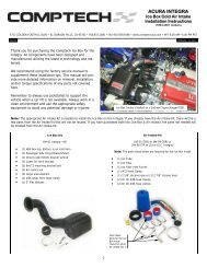
DETERMINING HOOD CLEARANCENOTE: Check hood clearance be<strong>for</strong>e removing stock manifold.1. Use modeling clay or putty to make five small cones, two or three inches high.2. Position cones on air cleaner at front, rear, each side, and on center stud.3. Close hood to locked position and re-open.4. The height of the cones indicate the amount of clearance between the hood and the air cleaner. Record these measurements.AIR CLEANERCLAY CONECB EAD2-3"FORWARDBCEADHOOD CLEARANCEFORWARDMANIFOLD & CARBURETOR HEIGHT VS. PRO-FLO HEIGHT1. Remove air cleaner.2. Lay a straightedge (such as a yardstick) across the top of the carburetor fromfront to back.3. Measure from block and manifold end seal surfaces to straightedge.4. Record these measurements (height A and height B).5. Add height A and height B and divide by two to get the average height.6. The <strong>Pro</strong>-<strong>Flo</strong> manifold and air valve measures 7.55” at the (A) and 9.10” at therear (B).9. Compare the two measurements. If the <strong>Pro</strong>-<strong>Flo</strong> unit is taller, subtract thisamount from the hood clearance figure to determine new hood clearance.CAUTION: You must maintain at least 1/2-inch clearance between the hood and aircleaner because of engine torque. If you have insufficient clearance, a low profileair cleaner may solve the problem.HEIGHT BFORWARDHEIGHT AEMISSION CONTROLSThe <strong>Edelbrock</strong> <strong>Pro</strong>-<strong>Flo</strong> system will not accept stock emissions control systems. Check local laws <strong>for</strong> requirements be<strong>for</strong>e installing the <strong>Pro</strong>-<strong>Flo</strong>system. Not legal on pollution-controlled motor vehicles.Rev. 10/054<strong>Pro</strong>-<strong>Flo</strong> <strong>EFI</strong> Installation Instructions©2005 <strong>Edelbrock</strong> CorporationBrochure No. 63-0115
FUEL REQUIREMENTSBecause the <strong>Pro</strong>-<strong>Flo</strong> system uses an Oxygen sensor, you must use unleaded fuel only. Leaded fuels will damage the O2 sensor. If you do useleaded fuel in your vehicle, do not install the O2 sensor and do not operate the vehicle in the closed loop fuel mode.AUTOMATIC TRANSMISSION CHECKFor best per<strong>for</strong>mance, economy, and emissions, the shift point must be checked be<strong>for</strong>e and after the manifold change.NOTE: This check should be per<strong>for</strong>med ONLY at a sanctioned drag strip or test track.With the shifter in Drive, accelerate to wide open throttle from a standing start. Hold in this position, noting speedometer MPH when thetransmission makes the first 1-2 shift. After the <strong>Pro</strong>-<strong>Flo</strong> system has been installed, make the same test, again noting MPH of this first shift.If adjustment is necessary, we recommend use of the <strong>Edelbrock</strong> Throttle, Cruise Control, & Transmission Kick-Down Mounting Bracket #8031.The Turbo 350 and Turbo 200 feature a window to accommodate user adjustment of shift points at WOT.The transmissions in certain vehicles require precise adjustments. We recommend that you consult a reputable transmission shop <strong>for</strong> finaladjustments once the <strong>Pro</strong>-<strong>Flo</strong> system has been installed. Incorrect shift points can result in transmission damage.ENGINE CLEANING<strong>Edelbrock</strong> recommends that the <strong>Pro</strong>-<strong>Flo</strong> system be installed on a clean engine in order to prevent dirt from falling into the engine lifter valley orintake ports.1. Cover ignition. Use engine degreaser and a brush to thoroughly clean the manifold and the area between the manifold and valve covers.2. Rinse with water and blow dry.EXHAUST MANIFOLD HEAT RISER VALVEIf your vehicle is equipped with an exhaust manifold heat riser valve (typically located on the passenger side of the vehicle below the exhaustmanifold), remove the valve <strong>for</strong> proper operation. If applicable, any air injection tubes must be removed and holes in the exhaust manifoldplugged <strong>for</strong> proper operation.HEADERSFor best per<strong>for</strong>mance, headers are recommended. For this application, header primary tube diameter should be 1-3/4 inch, approximately 31inches long and terminating into a 3 inch collector. The remainder of the exhaust system should consist of dual exhaust and tail pipes, at least 2-1/4 inches in diameter with low back pressure mufflers.COOLING SYSTEMThe minimum requirements <strong>for</strong> the thermostat are 180° but the ideal thermostat is 195°. When the vehicle is at 175 or below, system will stayin cold start mode and not per<strong>for</strong>m properly.Rev. 10/055<strong>Pro</strong>-<strong>Flo</strong> <strong>EFI</strong> Installation Instructions©2005 <strong>Edelbrock</strong> CorporationBrochure No. 63-0115
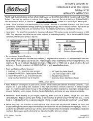
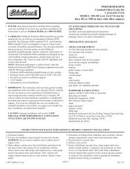
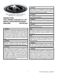
FUEL SYSTEMBecause your <strong>Edelbrock</strong> <strong>Pro</strong>-<strong>Flo</strong> system controls fuel delivery very differently than a carburetor, some conversions to your fuel system arenecessary. <strong>Pro</strong>-<strong>Flo</strong> electronic fuel injection requires high and constant fuel volume and fuel pressure. For this reason, a good primary fuel line iscritical. The <strong>Pro</strong>-<strong>Flo</strong> system includes a 3/8-inch high pressure fuel line which must be used as the primary fuel line. The fuel that bypasses theinjectors must be returned to the fuel tank via a return fuel line. If your vehicle is already equipped with a fuel pump bypass line, this line can beused as the return fuel line. If not, the original primary line may be used as the return line. If desired, an 8 foot length of 5/16 ID rubber hose issupplied <strong>for</strong> use as the return line.Many late-model cars are equipped with an additional fuel line which runs to a charcoal canister mounted on the driver side of the vehicle. Thisline MUST be re-installed after the fuel system conversion and MUST NOT be used as the return fuel line.FUEL PUMP AND FILTERThe <strong>Pro</strong>-<strong>Flo</strong> system uses a single <strong>Edelbrock</strong> high-pressure electric fuel pump which iscapable of pumping 50 psi. The pump relay will shut down the pump if it does not receive anengine-run signal from the ECU, as in the case of a stall. This safety precaution is necessarywhen using a high-pressure fuel line. The provided fuel filter should be mounted between theengine compartment and the fuel pump to allow fuel to be pushed through the filter ratherthan drawn through. Electrical connectors should face the front of vehicle. Make sure thefuel pump is mounted at or below the bottom of your fuel tank. If the pump is mounted abovethis point, fuel pump failure will occur.Engine SideTank SideFUEL PRESSURE REGULATORFuel pressure is as important as fuel volume, particularly in fuel injection. The <strong>Pro</strong>-<strong>Flo</strong> fuelpressure regulator maintains a constant pressure at the injectors with a spring loaded bypassto the return fuel line. Manifold Absolute Pressure references the regulator diaphragmto maintain constant pressure across all 8 injectors, regardless of fluctuating manifoldpressure (vacuum) level. The fuel that is not injected is returned to the fuel tank via the returnfuel line.RETURN FUEL LINEDue to the high fuel pressure used by the <strong>Pro</strong>-<strong>Flo</strong> system, the supplied 3/8-inch high pressure fuel line MUST be used as the primaryfuel line, and a bypass fuel return line must be installed. There are three options <strong>for</strong> installing a bypass return line.1. Use the 5/16 rubber fuel line provided with the system as the fuel return line.2. Use the vehicle’s existing primary line as the fuel return line with modification to the pick up as described below.3. Use the vehicle’s existing return line (if so equipped) as the fuel return line. This option applies only to vehicles previously equipped with fuelinjection. If the vehicle is not already equipped with a return line, some fuel tank modifications are required <strong>for</strong> routing the return linethrough the sending unit plate back into the tank. The first two methods listed below require some welding and should be done by aprofessional radiator or fuel system repair shop.Rev. 10/056<strong>Pro</strong>-<strong>Flo</strong> <strong>EFI</strong> Installation Instructions©2005 <strong>Edelbrock</strong> CorporationBrochure No. 63-0115
RUBBER RETURN LINE METHODDrill a 5/16-inch hole in the sending unit plate adjacent to where the main line enters the tank. This will be the hole <strong>for</strong> your return line. Insert ashort length of 5/16-inch hard line (available at most radiator shops) into the hole and weld it to the sending unit plate. The hard line shouldextend through the hole 1 to 2 inches on each side of the plate. Connect a length (at least 4 inches) of 5/16-inch rubber return line hose to thehard line that will extend into the tank. Connect the rubber line to the fuel pickup line using tie wraps.BULKHEAD FITTING METHODDrill a 9/16-inch hole in the sending unit plate adjacent to where the main line enters the tank. This will be the hole <strong>for</strong> your return line. Insert a#6 AN bulkhead fitting (available at most radiator shops) into the hole, the narrow end of the fitting on the inside of the plate. Apply a rubberwasher or RTV sealant and fasten the fitting to the plate with the nut. Connect a length (at least 4 inches) of flexible return line (rubber orbraided hose) to the fitting end. Connect the return line to the fuel pickup line using tie wraps.NOTE: THIS METHOD REQUIRES NO WELDING OF THE FUEL SYSTEM.NOTE: Whichever method you use to install the return fuel line, becareful to keep the end of the line away from the fuel pickup, asshown. Otherwise, aerated return fuel can be drawn into the pickup.Rev. 10/057<strong>Pro</strong>-<strong>Flo</strong> <strong>EFI</strong> Installation Instructions©2005 <strong>Edelbrock</strong> CorporationBrochure No. 63-0115
BULKHEAD FITTING METHODHARD RETURN LINE METHODDrill a 5/16-inch hole in the sending unit plate adjacent to where the main line, enters the tank. This will be the hole <strong>for</strong> your return line. Insert alength of 5/16-inch hard line (available at most radiator shops) into the hole and weld it to the sending unit plate. The hard line should extendthrough the hole 1 to 2 inches on the outside of the plate. On the inside of the plate, the hard line should follow the contours of the fuel pickupline. Bend the end of the return line away from the sock on the end of the fuel pickup line. Solder or weld the return hard line to the fuel pickupline.HARD RETURN LINE METHODRev. 10/058<strong>Pro</strong>-<strong>Flo</strong> <strong>EFI</strong> Installation Instructions©2005 <strong>Edelbrock</strong> CorporationBrochure No. 63-0115
NOTE: ALL WELDING AND SOLDERING OF THE FUEL SYSTEM MUST BE PERFORMED BY APROFESSIONAL RADIATOR AND/OR FUEL SYSTEM REPAIR SHOP.FUEL SYSTEM INSTALLATION1. Drain the fuel tank.2. Remove all fuel lines from the tank and from the carburetor.3. Remove the fuel tank.NOTE: While the fuel tank is removed from the car, it is recommended that it be professionallycleaned in order to remove any rust or dirt that may have accumulated inside and which coulddamage the injectors.4. Remove the sending unit from the fuel tank. Refer to the RETURN FUEL LINE methods above <strong>for</strong>installing the bypass fuel return line.5. Install the provided 3/8-inch primary fuel line directly above the original line, which maynow serve as a return line. Use large radius bends. Avoid the exhaust pipe and anysharp edges.NOTE: The 3/8-inch high pressure fuel line supplied with the <strong>Pro</strong>-<strong>Flo</strong> system must beused as the primary fuel line.6. If you do not use the original fuel as the return line, route the return line directlyalongside the provided 3/8-inch primary fuel line.7. Mount the fuel pump between the tank and the fuel filter as low and as close to thefuel tank as possible. The pump is directional. Electrical connectors should face thefront of vehicle. The fuel pump needs to be at or below the level of fuel in the tank.8. Mount the fuel filter between the fuel pump and the engine.9. Re-install the modified sending unit plate to the clean fuel tank.10. Reinstall the fuel tank.11. Attach the primary line and return line to the sending unit plate on the tank.12. Re-attach all other fuel lines at the tank (vapor purge lines, etc., if so equipped).13. Secure the primary and return fuel lines with the provided tie-wraps, or with Adel clamps ifavailable.14. Re-attach all fuel lines to the induction system once it has been installed.15. Use the 10-foot wiring harness to connect the fuel pump to Connector J3 of the Main SystemHarness. Route the harness away from the exhaust pipe and any sharp edges. This harnessmay be cut to length. Replacement terminals are provided with the <strong>Pro</strong>-<strong>Flo</strong> system. Cover theconnection to the positive terminal with the sleeve and tie wrap provided. Refer to the MAINSYSTEM HARNESS section of this manual <strong>for</strong> details.16. Be<strong>for</strong>e starting the engine, turn the ignition key to the ON position 4 or 5 times to prime the electric fuel pump, fuel lines, and fuel rails. Youshould hear the pump run <strong>for</strong> approximately 2 seconds each time. Check the entire fuel system <strong>for</strong> leaks. Refer to the SYSTEM START-UPsection of this manual <strong>for</strong> details.Rev. 10/059<strong>Pro</strong>-<strong>Flo</strong> <strong>EFI</strong> Installation Instructions©2005 <strong>Edelbrock</strong> CorporationBrochure No. 63-0115
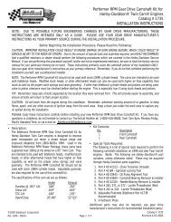
INDUCTION SYSTEMThe <strong>Edelbrock</strong> <strong>Pro</strong>-<strong>Flo</strong> system delivers fuel and air to the engine via the induction system consisting primarily of a manifold, 4-barrel air valve,fuel rails, and fuel injectors. The induction system is fully assembled, tested, seal checked, and flowed at the factory and is as easy to install as amanifold. DO NOT DISASSEMBLE any of these components during installation.FUEL RAILSThe extruded aluminum rail assembly routes the high pressure fuel to the injectors.Aluminum rails have an advantage over soft rails both in terms of style and safety.INTAKE MANIFOLDThe new <strong>Edelbrock</strong> manifold used with the <strong>Pro</strong>-<strong>Flo</strong> system is very similarto the successful Victor Jr. high-per<strong>for</strong>mance single-plane manifold, buthas been designed specifically <strong>for</strong> electronic fuel injection applications.4-BARREL AIR VALVEThe <strong>Pro</strong>-<strong>Flo</strong> system uses a progressive linkage valve body with four throttle bladesarranged in a conventional 4-barrel pattern, with staged secondaries. The air valvecan flow up to 1000 cfm at 1.5" of mercury when wide open.FUEL INJECTORSThe <strong>Pro</strong>-<strong>Flo</strong> #<strong>3550</strong> & <strong>3551</strong> systems use high impedance pintle-type fuel injectors.The injectors used with #<strong>3550</strong> are capable of flowing 44 lbs./hr. at 50 psi. The #<strong>3551</strong>uses 29 lbs./hr. injectors. The injectors mount directly onto the manifold, one at eachport, <strong>for</strong> fuel delivery that is precisely controlled and instantaneously injected.Rev. 10/0510<strong>Pro</strong>-<strong>Flo</strong> <strong>EFI</strong> Installation Instructions©2005 <strong>Edelbrock</strong> CorporationBrochure No. 63-0115
PRE-INSTALLATIONBe<strong>for</strong>e installing the induction system, take the following steps to ensure successful installation and per<strong>for</strong>mance1. Check all components thoroughly <strong>for</strong> damage.2. Make sure all throttle linkages open entirely and close freely.3. Make sure all fuel inlet and vacuum ports are free from packing material.4. Check the installation kit <strong>for</strong> proper parts.REMOVING THE STOCK CARBURETOR AND MANIFOLD1. Disconnect battery.2. For ease of installation, keep all parts in order.CAUTION: Do not remove manifold if engine is hot.3. Drain radiator coolant (radiator drain plug is typically located on lower right facing engine).4. Remove gas cap to relieve pressure. Disconnect fuel line and plug. Replace gas cap.5. Disconnect all linkage from carburetor such as throttle, throttle springs, transmission, cruise control and automatic choke.6. Tag and remove coil wires and sensor wires.7. Remove previously marked vacuum lines.8. Remove radiator hose, thermostat housing and thermostat, if mounted on manifold.9. Remove all brackets from the manifold.10. Loosen or remove valve cover bolts <strong>for</strong> manifold removal and replacement. It may be necessary to replace valve cover gaskets, if broken, toprevent oil leakage.PORT SURFACE CLEANINGWhen cleaning old gaskets from head surfaces, lay rags in the lifter valley and stuff paper intothe ports, to prevent pieces of the old gasket from falling into ports and combustion chambers.When clean, remove paper, making sure that all particles fall on the rags in the lifter valley.Remove rags, and wipe surfaces clean with rags soaked in lacquer thinner in order to removeoil or grease. NOTE: This procedure is necessary to ensure proper sealing.INSTALLING FITTINGS, PIPE PLUGS, AND STUDSDo not over-tighten or cross-thread fittings, pipe plugs, studs, or bolts in your aluminum manifold. Damage to threads or a cracked mountingboss may result unless caution is used when installing accessories.Use high quality pipe thread sealant on all threads. Install fittings from your stock manifold.Rev. 10/0511<strong>Pro</strong>-<strong>Flo</strong> <strong>EFI</strong> Installation Instructions©2005 <strong>Edelbrock</strong> CorporationBrochure No. 63-0115
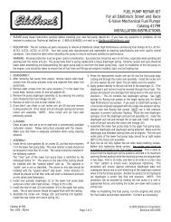
GASKET SURFACE PREPARATIONCAUTION: Replace all gaskets as recommended. Do not use race-type non-embossed gaskets <strong>for</strong> street applications. Due to materialdeterioration under street driving conditions, internal vacuum and oil leaks may occur.We recommend Fel-<strong>Pro</strong> Printoseal gaskets #1212 orequivalent. Do not use Fel-<strong>Pro</strong> Permatorque Blue gaskets, which are designed <strong>for</strong> use on stock cast iron intake manifolds only.1. Check gaskets on head surface and manifold to make sure they are correct. Embossed side faces up (NOTE: In some cases, there may be adifferent right and left side gasket. Make sure both are placed correctly.).2. Coat head surface and both sides of gaskets with <strong>Edelbrock</strong> Gasgacinch #9300.3. Apply Loctite 598 OEM High Temperature Silicone Gasket around water passages on head surface.4. Gaskets and surface will become tacky to the touch within a few minutes. Carefully place gaskets on head surface, aligning ports and boltholes.5. <strong>Edelbrock</strong> recommends the use of Loctite 598 OEM High Temperature Silicone Gasket instead of end seal gaskets. Apply a 1/4-inch thickbead of sealant across each end seal surface, overlapping the intake gasket at the four corners (NOTE: Use the recommended siliconsealer. Others may damage the O2 sensor. This method eliminates end seal slippage and deterioration. For ease of installation, werecommend using <strong>Edelbrock</strong> Manifold Bolt and Washer Kit #8564.).6. Apply <strong>Edelbrock</strong> Gasgacinch #9300 to port surface of the manifold and to the head surfaces to ensure a good seal.7. Apply RTV gasket sealer around water passages on the manifold.8. Surfaces will become tacky to the touch within a few minutes.INDUCTION SYSTEM INSTALLATION1. Carefully position manifold and air valve on engine, centering bolt holes with the bolt holes in the head.2. Apply thread sealer or Teflon tape to bolt threads where exposed to water or oil.3. Hand tighten all bolts.4. Torque all manifold bolts to 25 ft/lbs. Torque in the sequence illustrated.5. Re-connect throttle linkage and springs, transmission, cruise control, and fuel lines. Check all linkage <strong>for</strong> smooth throttle operation from idleto Wide Open Throttle.Note: Do not install with a throttle rod, use a cable actuated throttle.6. Re-tighten the valve cover bolts.117153214610Kit #<strong>3550</strong> & #350112816411359Rev. 10/0512<strong>Pro</strong>-<strong>Flo</strong> <strong>EFI</strong> Installation Instructions©2005 <strong>Edelbrock</strong> CorporationBrochure No. 63-0115
SENSORSThe <strong>Edelbrock</strong> <strong>Pro</strong>-<strong>Flo</strong> system interprets overall engine operating conditions and fuel/spark requirements based on readings from sensors thatmeasure specific engine conditions.The <strong>Pro</strong>-<strong>Flo</strong> system includes five sensors:1) Manifold Absolute Pressure2) Manifold Air Temperature3) Coolant Temperature4) Throttle Position5) Exhaust Oxygen (O 2 )These sensors, with the exception of the O 2 , are designed as an integral part of the induction system and require no installation. The O 2 sensormust be installed on the exhaust pipe near the engine with a welded fitting.MANIFOLD ABSOLUTE PRESSURE SENSORThe Manifold Absolute Pressure sensor, mounted on the air valve with a bracket, converts airpressure (load) in the manifold, to an analog signal sent to the ECU. For more in<strong>for</strong>mation onManifold Absolute Pressure, refer to the section on Speed Density Electronic EngineManagement. This sensor is connected to the Main System Harness by Connector J9.MANIFOLD AIR TEMPERATURE SENSORThe Manifold Air Temperature sensor, is a thermistor device which measures air temperature. This sensor must be installed intothe air cleaner base. Drill the air cleaner base with a 3/4” drill, deburr any sharp edges, install MAT sensor grommet, then slidesensor into grommet. This sensor is connected to the Main System Harness by connector J11.NOTE: The systems that have the MAT sensor in the intake plenum area, can be moved to the air cleaner if necessary to obtain additionalvacuum ports.Rev. 10/0513<strong>Pro</strong>-<strong>Flo</strong> <strong>EFI</strong> Installation Instructions©2005 <strong>Edelbrock</strong> CorporationBrochure No. 63-0115
COOLANT TEMPERATURE SENSORThe Coolant Temperature Sensor is a thermistor device like the Manifold Air Temperature sensor.Resistance varies as coolant temperature rises and lowers. The Coolant Temperature Sensor is located atthe front of the manifold on the driver’s side, and is connected to the Main System Harness by ConnectorJ10.THROTTLE POSITION SENSORThe Throttle Position Sensor, an integral part of the <strong>Pro</strong>-<strong>Flo</strong> throttle body, measures throttleangle. This sensor requires adjustment as described in the SYSTEM START-UP section ofthis manual. It is connected to the Main System Harness. by Connector J8.OXYGEN (O 2 ) SENSORAn oxygen sensor, installed on the header collector pipe, measuresexhaust gas oxygen content and is used by the ECU to manage fueldelivery under closed loop control. Installing the sensor requiresdrilling a 1/2-inch hole in the passenger-side header collector. Thesensor is held in place with the provided fitting which must beprofessionally welded into place. The red-lean/green-rich light on theCalibration Module is also controlled by the O 2 sensor. The O 2 sensoris connected to the Main System Harness by Connector J21. Forinstallation details, refer to the FUEL SYSTEM section of this manual.NOTE: Prior to installing your O 2 sensor check the wires leading intothe weather pack plug and make sure the odd colored wire is in themiddle.Rev. 10/0514<strong>Pro</strong>-<strong>Flo</strong> <strong>EFI</strong> Installation Instructions©2005 <strong>Edelbrock</strong> CorporationBrochure No. 63-0115
O 2 SENSOR INSTALLATIONThe exhaust gas oxygen content is determined by the oxygen sensor. The sensor signals the ECU, which compensates when the air/fuel mixtureis either rich or lean.NOTE: It is recommended that the O2 sensor installation be per<strong>for</strong>med by a professional muffler shop.1. Double check header gaskets, replacing if necessary.2. Drill a 1/2-inch to 9/16-inch hole in the passenger-side header collector reducer, as close to the header flange as possible. (1" to 3" away)NOTE: Be<strong>for</strong>e drilling, make sure the O2 sensor will be mounted horizontally and within reach of the harness connector. Check to ensureadequate clearance <strong>for</strong> the sensor, taking into consideration engine movement.3. Fit the provided fitting into the hole in the exhaust pipe and weld into place.4. Once it has been welded into place, clean the threads in the center of the fitting. If your exhaust is coated tap bung threads to ensure agood ground <strong>for</strong> the 0/2 sensor.5. Thread the O2 sensor into the fitting. A high-heat anti-seize compound is included and needs to be applied to the sensor threads.NOTE: The O2 sensor has 18mm x 1.25 spark plug threads.6. Attach the O 2 sensor to the main system harness Connector J21. Refer to the MAIN SYSTEM HARNESS section of this manual.NOTE: UNLEADED FUEL MUST BE USED ONCE THE O2 SENSOR HAS BEEN INSTALLED.COATED HEADERS: Use a digital OHM meter to measure the resistance between cylinder head bolt and the body of the installed 0/2sensor. The reading should be less than 1 OHM. If it is higher, you need to provide a ground to the 0/2 sensor mount.Rev. 10/0515<strong>Pro</strong>-<strong>Flo</strong> <strong>EFI</strong> Installation Instructions©2005 <strong>Edelbrock</strong> CorporationBrochure No. 63-0115
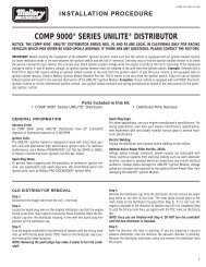
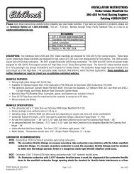
MAIN SYSTEM HARNESSIf the ECU is the brain of the <strong>Edelbrock</strong> <strong>Pro</strong>-<strong>Flo</strong> system, the Main System Harness is the central nervous system. Constructed with SAE gradewires and the most up-to-date Weatherpak connectors, the Main System Harness is a generic harness that can be used with any application <strong>for</strong>which the <strong>Pro</strong>-<strong>Flo</strong> system is designed.This diagram illustrates the entire <strong>Pro</strong>-<strong>Flo</strong> Main System Harness. Each connector is identified by a alpha-numeric code as listed below.O2SensorMAPSENSORTPSSENSORABCABCABCBlkRetVrefRetVrefTPSBluECU PwrGNDPplGrnECU TxECU RxGNDO2 SensDRP RetECU RxSensor RetMAPTPSINJ BOrange123456789101112131415161718Gray1920212223242526272829303132333435OrangeGND BlkECU PwrDRPPpl/WhtIGN RetSPK OutECU TxPUMPCOOL SensVrefMATINJ DINJ CIACINJ ABlkBlkDRP RetADISTRIBUTOR+12V BDISTRIBUTOR(HALL SENSOR)C2.7K OhmABCDIGNITIONAMPLIFIERTan/WhtGray Yel/BlkABCOOLANTTEMPERATURETanABINLET AIRTEMPERATUREGrnOrangeBlk/YelPink/BlkBlk/WhtBlk/GrnBlk/RedEFDPink/BlkBlkOrangeCA20 AMPFUSEB A3 AMPFUSEB AABABABABABFUELPUMPOrange+12VBATTERYStart/Run Power, +12V(From Ignition Switch)IDLE SPEEDCONTROLINJECTORS2 and 7ABABINJECTORS3 and 4ABINJECTORS1 and 8ABINJECTORS5 and 6GreenCAL.ECUABRev. 10/0516<strong>Pro</strong>-<strong>Flo</strong> <strong>EFI</strong> Installation Instructions©2005 <strong>Edelbrock</strong> CorporationBrochure No. 63-0115
BAACONNECTORSThe “J” coding is <strong>for</strong> illustration purpose only. The connector ends DO NOT have a “J” code stamped on themJ1 ECUJ2 Calibration moduleJ3 Pump harnessJ8 Throttle Position SensorJ9 Manifold Absolute Pressure sensorJ10 Coolant Temperature sensorJ11 Manifold Air Temperature sensorJ12 DistributorJ13 Injector, number 1 cylinderJ14 Injector, number 3 cylinderJ15 Injector, number 5 cylinderJ16 Injector, number 7 cylinderJ17 Injector, number 2 cylinderJ18 Injector, number 4 cylinderJ19 Injector, number 6 cylinderJ20 Injector, number 8 cylinderJ21 Oxygen sensorJ22 Connector to IACJ23 RelayJ24 ECU fuseJ25 Pump fuseJ9MAPBLKREDJ17 J18 J19 J202 46 8ORNBLK ORNRED BLKORNBLKORNGRNWHTA B CTPSJ8BLKGRNGRYC B ABLUGRYBLKJ22IACJ12DISTGRNORNA B CP27B ABLKPPLREDMATJ11BJ10COOLJ27A BBLKTANGRNORNJ167J155J143J131BLK/WHTYEL/BLKBLK/YELORNBLK/REDORNBLK/WHTORNBLK/GRNORNBLKRT1ENGINEGROUNDSJ26 Ignition amplifierJ27 IAC connectorP27 IAC connector to main harnessRT1 Engine groundRT3 StarterBLKGRYWHTORNFIREWALLABCDJ23RELAYJ26IGN AMPRT 3+12V(STARTER)J25PUMPFUSE20 AMPPNK/BLKJ24ECMFUSE3 AMPSTART/RUNPOWERORNBLKB AORNPPLBLKJ3PUMPABCJ21O2J1ECM35 19118J2CAL MODINSTALLATION1. Inspect the Main System Harness, making sure that all connectors andgrounds are properly in place.2. Because the harness extends from the engine compartment into thepassenger compartment, a hole must be drilled in the firewall on thepassenger side. Cut two overlapping 1 1/4-inch holes on a 1-inch center inthe firewall. Saw the pointed edges to create an oval-shaped hole.NOTE: An alternative to this method is to cut a single 1 3/4 inch hole.3. Extend the fuel pump relay, ECU connector, and Calibration Module relaythrough the firewall hole into the passenger compartment.NOTE: The T-connectors at the joints of the Main System Harness are closedby snap fasteners which can be opened by hand or with a flatheadscrewdriver. Once open, the T-connectors can be rotated <strong>for</strong> ease ofinstallation, if necessary.4. The 3 1/2 x 2 1/4-inch aluminum plate included on the harness mounts over the firewall hole using four hex head sheet metal screws.NOTE: Start the screw holes with a pointed punch or small drill.5. The wire harness is assembled with the aluminum plate flush against a T-connector. The black plastic casing on the wire harness can becut to allow the plate to slide up the harness to the correct location. Once the harness is in place, the casing should be reattached on bothsides of the firewall.CAUTION: When feeding the wire harness through the firewall, be careful to not damage the wires against the cut sheet metal.6. A rubber grommet is provided to protect the wires in the aluminum plate. Use RTV to seal the plate to the firewall.7. Install all connectors according to the list and diagrams. The harness has been designed so that each connector is unique and will fit only toits correct match. There is only one possible installation combination; it cannot be installed incorrectly.Rev. 10/0517<strong>Pro</strong>-<strong>Flo</strong> <strong>EFI</strong> Installation Instructions©2005 <strong>Edelbrock</strong> CorporationBrochure No. 63-0115
The Throttle Position sensor attaches to the harness withConnector J8.The Manifold Absolute Pressure sensor attaches to theharness with Connector J9.The Coolant Temperature sensor attaches to the harnesswith Connector J10.The Manifold Air Temperature sensor attaches to theharness with Connector J11.Only the fuel injector connectors are identical, but they are placed inlogical sequence. Refer to the diagram when installing the harnessconnectors to the fuel injectors. In addition to the Main System Harness,the <strong>Pro</strong>-<strong>Flo</strong> system includes these shorter harnesses:A. IAC to Main System HarnessB. Ignition amplifier to distributorC. Fuel pump to Main System HarnessRev. 10/0518<strong>Pro</strong>-<strong>Flo</strong> <strong>EFI</strong> Installation Instructions©2005 <strong>Edelbrock</strong> CorporationBrochure No. 63-0115
A.This 5-inch IAC wiring harness is attached between the Idle Air Control, mounted on the air valve, and Connector J3 on the Main System Harness.B.This 3-foot ignition amplifier wiring harness is attached to the distributor cap with the connector at right above, and at the ignition amplifier withthe connector on the left above. The ground goes to the rear of the cylinder head. When used with a small cap distributor or any distributor withan external ignition coil, this harness must be slightly modified. The three wire leads at the distributor connector (on the right below), must be cutfrom the connector (or released with a small screwdriver) and individually routed using the provided terminals. The black wire may be removedbetween the connection on right above and the 3/8" ring lug. The 3/8" ring lug must still be grounded on the rear of cylinder head. The red andbrown wires are routed as follows:RED: ignition coil positive (+) terminal +12 start/run also.BROWN: ignition coil negative (-) terminal Sleeves and tie-wraps are provided to fit over the terminals once the wires are is installed.37"27"Red+NON HEI Coil12 Vdc from Vehicle HarnessRemove Black at this point OnlyBlack Ground to Cylinder HeadBrown-Rev. 10/0519<strong>Pro</strong>-<strong>Flo</strong> <strong>EFI</strong> Installation Instructions©2005 <strong>Edelbrock</strong> CorporationBrochure No. 63-0115
C.The connector on left end (as drawn) of this 10-foot fuel pump wiring harness attaches to connector J3 on the Main System Harness. The twoconnectors on the right connect to the positive (+) and negative (-) terminals on the fuel pump. A sleeve and tie-wrap are provided to fit over thepositive terminal once the connector is installed. This sleeve prevents the clamp from shorting the fuel pump terminals.B ABLKORN10'ORNBLK-+POS TERM(ORN WIRE)OUT+ –NEG TERBLK WIREFUEL OUTThe diagram below illustrates how the ignition amplifier, distributor, ignition amplifier wiring harness, and Main System Harness are connected.A KEY ON wire (Pink with black stripe) is also included in the <strong>Pro</strong>-<strong>Flo</strong> system. This wire connects to the fuse box. Make sure there is power withthe key on and also while cranking.REFER TO VEHICLE REPAIR MANUAL FOR WIRING DIAGRAM, IF NECESSARY.A B CREDBRNBLKREDBRNBLKCOIL WIRING HARNESSFROM MAIN HARNESSPNKENGINE GROUNDJ29IGNITIONAMPLIFIERBLUBRNPNKGRAYPPLWHTJ26WHTC– GND B+TACH BATBATSTART/RUNPOWERFROM MAIN HARNESSELECTRONIC CONTROL UNIT / SYSTEM ECUThe Electronic Control Unit (ECU) must be mounted away from moisture, excessive heat,or vibration. Underneath the dashboard on the passenger side, or behind the glove boxare recommended locations.Rev. 10/0520<strong>Pro</strong>-<strong>Flo</strong> <strong>EFI</strong> Installation Instructions©2005 <strong>Edelbrock</strong> CorporationBrochure No. 63-0115
IGNITION SYSTEMA new distributor is not required with the <strong>Edelbrock</strong> <strong>Pro</strong>-<strong>Flo</strong> system. The system has been designed to allow you to convert your stockdistributor, large cap or early small cap, mechanical or computer-controlled, into a Multi-Port Fuel Injection compatible Hall effect electronicdistributor. Optional conversion distributor bodies are the MSD #8365 and Accel #9109. A Mallory #6148201 may be used as is, withoutper<strong>for</strong>ming the conversion.HALL EFFECT SENSORA Hall effect distributor operates with a sensor that generates a pulse trainindicative of engine position and speed. This type of distributor is required <strong>for</strong>sequential fuel injection, and also provides high ignition timing accuracy. The <strong>Pro</strong>-<strong>Flo</strong> system includes everything you need <strong>for</strong> this distributor conversion. Theconversion is a simple matter of disassembling your stock distributor and installingthe Hall effect sensor, sensor plate, and shutter wheel provided with the package.Since the ECU controls spark advance, a mechanical advance lock-out plate isprovided as well.SHUTTER WHEELThe Hall effect shutter wheel is designed with seven wide shutter teeth and one narrowshutter tooth. The narrow tooth indicates the Number One cylinder position, and isnecessary <strong>for</strong> the ECU to establish proper phasing of the injector firing order. For thisreason, correct installation of the shutter wheel is very important. If the shutter wheel isinstalled incorrectly, the injector firing order will not begin with the Number One cylinder.Narrow Tooth (#1)DISTRIBUTOR CONVERSION1. Rotate the engine to 10° Be<strong>for</strong>e Top Dead Center (BTDC) on cylinder #1 as seen on the damper, with therotor pointing approximately to Number One cylinder plug wire.2. Remove the distributor cap.3. Remove the distributor from the engine.4. Note position of rotor and mark the distributor housing where the rotor points to Number One cylinder.5. Remove the roll pin from the bottom of the distributor shaft, releasing the drive gear and shims.NOTE: Check the drive gear and oil pump drive shaft <strong>for</strong> signs of wear. Worn parts can damage thecamshaft and oil pump and should be replaced. This is especially true when a high per<strong>for</strong>mance oil systemis used, which generates a heavier load on the camshaft gear system.6. Remove the rotor and distributor shaft.NOTE: It is critical that the sensor plate fits securely in place and is level in relation to the distributorhousing.Rev. 10/0521<strong>Pro</strong>-<strong>Flo</strong> <strong>EFI</strong> Installation Instructions©2005 <strong>Edelbrock</strong> CorporationBrochure No. 63-0115
7. Remove all internal components from the distributor housing, including the vacuum advancediaphragm.8. Install the electronic Hall effect sensor and sensor plate, using the fastenersprovided. The sensor plate has been designed to fit into a small cap or large capdistributor. Only the fastening holes and sensor position differ. The circuit boardcomes factory set <strong>for</strong> large cap applications. For small cap distribution move thesensor to other mounting holes. See small cap section on next page.NOTE: It is critical that the sensor plate fits securely in place, and is level inrelation to the distributor housing.9. Install the shutter wheel on the bottom of the rotor mounting plate. The shutter wheel cannotbe installed from above the mounting plate and must be installed from the drive gear end of therotor shaft. The shutter wheel is fastened to the rotor mounting plate by two screws. On smallcap distributors, it is necessary to first install the provided aluminum ring spacer above theshutter wheel. When properly installed, the notched end of the rotor mounting plate will befarther from the narrow shutter tooth.NOTE: On small cap distributors, it may be necessary to file the stud holes of the shutterwheel to fit.Shutter Wheel10. If you are converting a mechanical advance distributor, the advance assembly weights shouldbe discarded. Replace them with the provided lock-out plate or weld. Secure the lock-outplate with the stock springs. If possible, have the shaft Tig welded to the rotor plate by aprofessional. If not, apply a small amount of RTV silicone to the underside of the rotor plate,and on each of the studs prior to installing the lock-out plate.Lock out plate11. Reinstall the distributor shaft into the distributor. The shutter wheel teeth should passthrough the Hall effect sensor without touching on either side of the sensor. The shutterwheel teeth may be carefully adjusted by hand to ensure clearance if necessary.Rev. 10/0522<strong>Pro</strong>-<strong>Flo</strong> <strong>EFI</strong> Installation Instructions©2005 <strong>Edelbrock</strong> CorporationBrochure No. 63-0115
12. When the drive gear is installed, the shutter wheel teeth must be deep enough into the Hall effectsensor to allow them to completely pass through the sensor at the proper depth, but not so deep as tomake contact with the sensor. On small cap distributors, the provided spacer must be used to providecorrect spacing <strong>for</strong> the shutter wheel. On large cap distributors, diamond-shaped shims are provided toallow <strong>for</strong> adjusting shutter wheel height.13. Install the drive gear, shims, and roll pin to the bottom of the distributor shaft. Shaft end play should be.015" to a maximum of .030".14. Hand turn the rotor in the distributor to make sure that the shutter wheel is deep enough into the sensor that no binding occurs, and to check<strong>for</strong> correct clearance between the shutter wheel teeth and the sensor. Shutter wheel teeth should not come up out the tapered area of thesensor.Shutter wheeltooth and sensorAlignment.15. If clearance is correct, drop the rotor over the screen studs and fasten with supplied lock washers and nuts. Thread sealing compound isrecommended as added insurance.16. When installing the shutter wheel and re-attaching the rotor, check that when rotated clockwise the leading edge of the narrow shutterwheel tooth is centered in the Hall effect sensor when the rotor is pointing to the Number One cylinder position.17. Be sure to test your distributor as described on the following page prior to re-installation.SMALL CAP DISTRIBUTOR CONVERSIONAdapting a small cap distributor to the <strong>Pro</strong>-<strong>Flo</strong> Hall effect system requires a few additional steps in theconversion. Note: Some cast iron distributors will require modification to fit the Hall effect sensorplate. You will need to use a mill or die grinder to remove material as needed.File to fit1. The Hall effect sensor mounts with different fastening holes on a small cap distributor. Refer to thephoto with Step 8 above <strong>for</strong> correct sensor position.Shutter Wheel2. The small cap distributor requires the installation of the provided spacer above the shutter wheel.Refer to the photo at Step 11 above.3. To use the shutter wheel on small cap distributors, it is necessary to first file the studholes of the shutter wheel to fit with the provided fasteners. The holes must be filedapproximately 0.030-inch. As shown at right. This modification provides clearancebetween the fillister screw heads and the teeth next to these slots. On some small capdistributors the head of these screws may have to be filed to clear the top of the hallsensor.File to fitSpacer4. In order to use the <strong>Pro</strong>-<strong>Flo</strong> system with a small cap distributor, or any distributor utilizingan external ignition coil, it is necessary to modify the 3-foot ignition amplifier harness.Refer to page 23, the MAIN SYSTEM HARNESS section of this manual <strong>for</strong> details.Rev. 10/0523<strong>Pro</strong>-<strong>Flo</strong> <strong>EFI</strong> Installation Instructions©2005 <strong>Edelbrock</strong> CorporationBrochure No. 63-0115
DISTRIBUTOR TESTINGBe<strong>for</strong>e re-installing the distributor, test to ensure that the conversion has been per<strong>for</strong>med correctly.1. Install the ECU and wiring harness and make all connections except the distributor.2. Disconnect electrical connections at the fuel pump. Unplug the 10-foot fuel pump harness from the Main System Harness. Refer to the MAINSYSTEM HARNESS section of this manual <strong>for</strong> details.3. Turn the key to the ON position without starting the engine. Check that the Idle Air Control (IAC) solenoid clicks on and off <strong>for</strong> approximately 2seconds.4. The <strong>Pro</strong>-<strong>Flo</strong> Calibration Module will receive power and display an RPM: 0 reading, among other parameters.5. Connect the distributor to the wiring harness and spin the distributor gear by hand. If thedistributor sensor is operating properly, the Calibration Module will display an RPMreading greater than 0. When the distributor stops spinning, the Calibration Module maydisplay NO COMMUNICATION <strong>for</strong> approximately 2 seconds. This is normal and indicatesthat the ECU is waiting <strong>for</strong> the next distributor signal be<strong>for</strong>e the allowed time expires.6. If an RPM greater than zero is indicated in step 5, re-install the distributor.REINSTALLING THE DISTRIBUTOR1. Make sure that the distributor sits completely down on the manifold boss and that thedrive gear has fully engaged the oil pump drive.2. Lift the rotor by hand to make sure that there is adequate endplay. Lack of endplayindicates that the rotor shaft is bottomed out on the oil pump shaft.3. Gaskets may be added at the bottom of the distributor shaft above the drive gear toadjust the endplay on either large cap or small cap distributors. Add gaskets one at atime, checking that the rotor shaft maintains sufficient endplay to prevent damage to thebushings. Recommended endplay is between 0.015- and 0.030- inch.4. Adjust the housing to ensure that the leading edge of the narrow shutter wheel tooth iscentered in the Hall effect sensor when the engine is at 10° BTDC on #1 cylinder.5. Lightly tighten the hold down clamp so that the distributor can still be turned todetermine final setting when checking the timing6. Re-attach the distributor cap, with the rotor pointing towards the No. 1 terminal.Narrow Tooth (#1)7. The distributor is connected to the Main System Harness with connector J12.8. A short ignition harness connects the distributor cap to the ignition amplifier, and toground at the rear of the cylinder head. A second connector connects the distributor capto a 12 volt vehicle source, Start/Run source (the BAT terminal on the HEI). Refer topage 23 the MAIN SYSTEM HARNESS section of this manual <strong>for</strong> more details.IGNITION AMPLIFIERThe <strong>Pro</strong>-<strong>Flo</strong> system uses the <strong>Edelbrock</strong> #3518 Ignition Amplifier, which must be mounted on aflat surface in the engine compartment away from exhaust headers or other areas thatgenerate heat. The wheel well panel and firewall are ideal locations. The ignition amplifierfeatures three connectors. One connector connects to the amplifier. Of the other twoconnectors, the female connector connects to Connector J26 on the main system harness.The male connector connects to the 3-foot harness running to the distributor. See the wiringdiagram in the MAIN SYSTEM HARNESS section of this manual.Rev. 10/0524<strong>Pro</strong>-<strong>Flo</strong> <strong>EFI</strong> Installation Instructions©2005 <strong>Edelbrock</strong> CorporationBrochure No. 63-0115
ADDING AFTERMARKET IGNITIONIf you are wishing to use a MSD 6AL or MSD 6-Digital ignition with your <strong>Pro</strong>-<strong>Flo</strong> fuel injection, follow the wiring diagram below.NOTE: When installing the MSD box, keep the red battery lead, the main MSD box, and the power leads to the ignition amplifier AWAY from theECU and it’s wires. Failure to do so will cause serious communication and running issues.IGNITION COILFROM MAIN HARNESSJ26BLKBLKWHTWHTENGINE GROUNDBLKBLKBRNREDBRNREDIGNITIONAMPLIFIERMSDGRNPPLNOT USEDMSD 6A+-REDSPLICEREDBLKWHTBATTERYSPLICESTART/RUN POWER (+12V)Rev. 10/0525<strong>Pro</strong>-<strong>Flo</strong> <strong>EFI</strong> Installation Instructions©2005 <strong>Edelbrock</strong> CorporationBrochure No. 63-0115
OTHER APPLICATIONSThe <strong>Pro</strong>-<strong>Flo</strong> system has been designed and calibrated specifically using the Chevrolet 454 c.i.d. <strong>Big</strong>-block with large-valve style cylinder heads(such as <strong>Edelbrock</strong>’s Per<strong>for</strong>mer RPM Street Cylinder Heads with 2.25-inch valves) and tubular headers as a baseline.It is unlikely that every engine on which the <strong>Pro</strong>-<strong>Flo</strong> system is installed will match this baseline combination. The system can be used with similarapplications, as long as the correct chip matching your cam profile is installed in the computer and necessary fuel calibration adjustments aremade. If your <strong>Big</strong>-block is not a 454, does not have headers, and uses small-valve style cylinder heads (such as Chevrolet aluminum HO headswith 2.02-inch valves), it may require additional tuning adjustments. For further in<strong>for</strong>mation refer to the SYSTEM SET-UP SECTION of the Owner’sManual.If you are running small-valve heads and/or you are not using tubular headers, it may be necessary to adjust the air/fuel ratio at WOT from 4000rpm and up. Refer to the table below <strong>for</strong> starting points <strong>for</strong> adjustments. Refer also to the SYSTEM SET-UP section in the Owner’s Manual. Usethe FUEL @ WOT screens (located under FUEL MODIFIERS) to adjust the fuel at each available RPM..It should not be necessary to lean the fuel calibrations at 12” or 18” vacuum.WARNING: Watch the Rich/Lean light on the Calibration Module. If the light indicates a lean condition (red) <strong>for</strong> more than a fraction of a second at06” vacuum or WOT you are too lean <strong>for</strong> safe engine operation at full load.SYSTEM START-UPOnce the <strong>Edelbrock</strong> <strong>Pro</strong>-<strong>Flo</strong> system has been installed, there are a few procedures you must follow to break-in the system. Carefully per<strong>for</strong>mingthese break-in procedures will ensure best results and optimal per<strong>for</strong>mance.Use this checklist to double-check the following areas BEFORE starting the car:❑ Has the battery been reconnected?❑ Has the radiator been refilled with coolant?❑ Has the gas tank been refilled?❑ Has the oil been replaced?❑ Have all linkages been reconnected?❑ Have all wiring harness connectors been connected?❑ Have all fuel lines been reconnected?❑ Has the exhaust system been completely re-installed?❑ Has the O 2 sensor been installed and connected?❑ Have resistor type spark plugs been installed?Distributor TestRefer to the “IGNITION SYSTEM” section of this manual, under “DISTRIBUTOR TESTING” <strong>for</strong> the proper procedure.Priming The Fuel PumpBe<strong>for</strong>e the engine is started, the fuel pump must be primed to pressurize the system and purge the fuel line of all air.1. Turn ignition key to the ON position. You should hear the fuel pump go on. It will pump <strong>for</strong> 2 or 3 seconds and disengage.2. Turn the key to the OFF position <strong>for</strong> 1 second.3. Turn the key to the ON position again. The pump will go on <strong>for</strong> another 2 or 3 seconds.4. Repeat this procedure until the pump has been cycled three or four times, and is primed. The tone of the fuel pump will change when all airis out of the fuel system.5. If there is no tone, or no change in tone, the system is not priming. Check the entire fuel system <strong>for</strong> leaks, from the fuel tank to the injectors.Rev. 10/0526<strong>Pro</strong>-<strong>Flo</strong> <strong>EFI</strong> Installation Instructions©2005 <strong>Edelbrock</strong> CorporationBrochure No. 63-0115
Testing The SensorsBe<strong>for</strong>e starting the engine, test all sensors.1. Turn the key to the ON position with the Calibration Module connected. The display will read:RPM: 0 FUEL: 0.0 mSVAC: 0.0” Hg SPK: 10°NOTE: A vacuum reading of other than 0.0” Hg may be displayed depending upon barometric pressure and air temperature. At extremealtitude, the vacuum reading may be as high as 5.0” Hg.2. Push the UP ARROW key once to display.TH2O: 76°F TPS: 13°TAIR: 77°F Volt: 12.0NOTE: The water and air temperatures displayed will vary depending on ambient conditions. The system voltage will vary depending on thecondition of the battery.3. Move the throttle to test the Throttle Position Sensor (TPS). The TPS reading should vary depending on throttle angle.4. If the Calibration Module displays any error messages, refer to the TROUBLESHOOTING section of this manual and the User’s Manual.NOTE: If the calibration module goes blank while cranking, the system is losing power. Check the Pink/Black wire attached to the 3 Ampfuse <strong>for</strong> +12V power with the ignition in the crank position and the run position <strong>for</strong> proper operation.Starting The EngineAfter the fuel pump has been primed and the engine has been started, bring the engine speed up to cam break-in RPM (physically holding thethrottle at 2000 to 2500 RPM <strong>for</strong> 10 to 20 minutes), following the cam break-in procedure as described in the CAMSHAFT section.Timing AdjustmentUse a timing light to re-time your engine. The following steps must be per<strong>for</strong>med after the induction system has been installed and the distributorhas been converted and re-installed. Refer to the INDUCTION SYSTEM and IGNITION SYSTEM sections of this manual.1. Remove spark plug from Number One cylinder.2. Remove coil wire from distributor and ground it.3. THIS STEP REQUIRES TWO PEOPLE OR USE OF A REMOTE STARTER SWITCH. While oneperson rotates the engine by slowly bumping the starter, the other holds his finger over theNumber One plug hole until compression is felt.4. Continue to bump starter until timing mark on the crankshaft pulley shows approximately 10degrees Be<strong>for</strong>e Top Dead Center.5. Position rotor to approximately align with the Number One cylinder plug wire terminal indistributor cap. Check that the leading edge of the narrow tooth on the shutter wheel (as theshutter wheel rotates clockwise) is centered in the sensor. Refer to the IGNITION SYSTEMsection in this manual <strong>for</strong> details.Rev. 10/0527<strong>Pro</strong>-<strong>Flo</strong> <strong>EFI</strong> Installation Instructions©2005 <strong>Edelbrock</strong> CorporationBrochure No. 63-0115
Setting Base Spark AdvanceAfter the camshaft has been broken in, the base timing of the engine should be re-set. Use a timing light and the <strong>Pro</strong>-<strong>Flo</strong> Calibration Module toaccurately set timing.1. Start the engine2. The Calibration Module screen will display this screen:RPM: ø FUEL: 0.0 msVAC: 0.0"Hg SPK: 10°3. Press the DOWN ARROW key once to reach this screen:ENTER to select4. Press the ENTER key to display this screen:Target Idle RPM:xxxxEXIT = SCROLL ENTER5. Press the UP ARROW key six (6) times until the module displays this screen:EXITBase Tim'g set: OFF= SCROLL ENTER6. Press the ENTER key. Press either ARROW key and the screen will display Base Tim’g set: ON.7. Set the base timing using a timing light and engine running at 1500rpm. Turn the distributor until 10° advance is set.8. Press the UP ARROW or DOWN ARROW key to turn Base Tim’g set to OFF.WARNING: DO NOT DRIVE THE VEHICLE WITH THE BASE TIM’G SET ON. SERIOUS ENGINE DAMAGE MAY RESULTNOTE: If you use an advance-type timing light, the degrees advance shown on the Calibration Module (SPRK:) should always agree with theactual reading at the crank with the timing light.9. Press the EXIT key. You can now leave this screen using the UP ARROW or DOWN ARROW keys.Idle AdjustmentThis procedure is a general recommendation, intended to help you tune up your <strong>Pro</strong>-<strong>Flo</strong> ® system.NOTE: In manual transmission cars, this procedure must be followed with the car in Neutral and with the clutch pedal pressed. In automatictransmission cars, this procedure must be followed with the car in Drive and with the brake pedal pressed.Rev. 10/0528<strong>Pro</strong>-<strong>Flo</strong> <strong>EFI</strong> Installation Instructions©2005 <strong>Edelbrock</strong> CorporationBrochure No. 63-0115
Idle Calibration <strong>Pro</strong>cedure• Prior to idle calibration, you need to have completed the "System Start-Up" procedure• Warm up engine to at least 175°F.Idle Control• Using the calibration module, Select MISC. MODIFIERS and, Set Idle Control OFF.Set Idle Mechanical Stop• Set the mechanical stop screw so that idle speed in park/neutral is 50-100 RPM higher than you want the engine to actuallyidle in gear with the idle control turned on. Typically 600 - 1000 RPM depending on the installed camshaft.• We find 650 RPM a good idle <strong>for</strong> our #3531 (with Per<strong>for</strong>mer-Plus camshaft) calibration.Set Throttle Position Sensor• Loosen the two Throttle Position Sensor (TPS), mounting screws, and rotate the TPS sensor to a setting of 13 degrees asobserved on the Calibration Module. This setting must be at 13 degrees after the idle adjustment is completed.Set Idle Fuel Modifier and Idle Spark Modifier• Using the calibration module, Select MISC. MODIFIERS and adjust Idle Spark and fuel Modifiers to obtain best idle quality.Idle quality will vary with engine design. Fuel and Spark setting will interact, particularly when you approach best settings.• You must establish a smooth idle prior to using Idle Control. Otherwise, the RPM will surge when Idle Control is turned on.Save Calibration• Re-check that the TPS setting is 13 Degrees.• Using the calibration module, Select MISC. MODIFIERS• Set IDLE CONTROL ON. Set TARGET IDLE to the same RPM established by the idle stop screw.• Save calibration settings to “A”Idle Speed Activity• Displayed on the calibration module, (Second Data Screen). The displayed value represents the amount of air that isbypassing the throttle blades of the air valve, Normal values range from 5% to 75%. This ensures that the computer canincrease or decrease the idle air flow to control idle speed.• If your have established a "good" idle set up, the RPM will remain nearly constant between in-gear and out-of-gear. The IdleSpeed Activity will change 10- 30% as it adjusts the idle speed.• The value of Idle Activity is 20% when Idle Speed Control is off.Idle Speed Activity Modifier• This function is locked out when Idle Control is off as indicated by "XXXX" in the Target idle display on the Calibration ModuleDisplay.• The Idle Speed Activity Modifier biases the Idle Activity duty cycle, +/50%, this has the effect of changing RPM control loopresponse time.• We recommend that this value be set to zero modification except in extreme cases.Rev. 10/0529<strong>Pro</strong>-<strong>Flo</strong> <strong>EFI</strong> Installation Instructions©2005 <strong>Edelbrock</strong> CorporationBrochure No. 63-0115
Electronic Engine ManagementThe <strong>Edelbrock</strong> <strong>Pro</strong>-<strong>Flo</strong> system uses the Speed-Density method of electronic engine management, in which fuel and spark requirements arebased on engine speed (RPM) and engine load (manifold pressure and temperature).The Electronic Control Unit (ECU) receives signals regarding engine speed (from the distributor), and the three load factors consisting of coolanttemperature (ECT), Manifold Absolute Pressure (MAP) and air temperature (MAT). Once the ECU has determined the engine operating point (RPMand Load factor), it uses tables programmed into it to instantly calculate correct spark advance and injector pulse width.A more detailed description of electronic engine management can be found in the Owner’s Manual <strong>for</strong> your <strong>Pro</strong>-<strong>Flo</strong> system. One possible point ofconfusion does need to be clarified. The <strong>Pro</strong>-<strong>Flo</strong> system displays vacuum rather than the less-familiar manifold pressure. This vacuum reading isbased on the following SAE standard atmosphere:Barometer 29.5 in HgTemperature 77°FBecause of this, the vacuum figures displayed on the Calibration Module may differ from the vacuum indicated by a true vacuum gauge,particularly at extreme high or low altitude.FUEL MODIFIER TABLEFUEL MODIFIER TABLERPM1000 2000 3000 4000 5000 7000WOTLOAD6"12"18"SPARK MODIFIER TABLESPARK MODIFIER TABLERPM1000 1750 2500 3500 4500 6000The <strong>Pro</strong>-<strong>Flo</strong> tables come pre-set from factory <strong>for</strong> the enginecombination that you specified when you ordered your computerchip. This factory calibration must be altered with the CalibrationModule to optimize per<strong>for</strong>mance. The Calibration Module allowsyou to modify the fuel and spark tables at various engine speedsand levels of vacuum. These tables may be used <strong>for</strong> recordingyour modifications to the base table with your own fuel pulsewidth and spark advance figures. For in<strong>for</strong>mation on using theCalibration Module to enter your figures into the <strong>Pro</strong>-<strong>Flo</strong> ECU referto the CALIBRATION MODULE section in the Owner’s Manual.WOTLOAD9"18"Rev. 10/0530<strong>Pro</strong>-<strong>Flo</strong> <strong>EFI</strong> Installation Instructions©2005 <strong>Edelbrock</strong> CorporationBrochure No. 63-0115
PRO-FLO QUICK TUNING GUIDEThese are basic instructions to help in understanding the tuning of your <strong>Pro</strong>-<strong>Flo</strong> fuel injection system. For detailed technical in<strong>for</strong>mation ontuning your <strong>Pro</strong>-<strong>Flo</strong>, see the <strong>Pro</strong>-<strong>Flo</strong> Owner’s Manual. This guide has been developed after talking with end users that are not familiar with thetechnical in<strong>for</strong>mation provided in the Owner’s Manual.This guide is based on our simple graph that shows the 24 fuel cells that you can tune in to result in a clean and powerful engine. Werecommend when you have your <strong>Pro</strong>-<strong>Flo</strong> installed, you have the idle tune up completed and then drive the vehicle to determine what amount oftuning is needed <strong>for</strong> general driving. If the unit is driveable, this is the method to use <strong>for</strong> ease of tuning. On page 6 of this installation manual,there is a fuel grid that can be used as the map on which to locate and then tune any drivability problems. Simply drive the vehicle and note anyareas that have problems. Circle those areas as a baseline.When circling the area where a problem exists, you are circling the RPM and Vacuum reading that is present when the problem occurs.Note whether it is running rich (green light) or lean (red light) at each problem area. Once any problem areas have been located and noted rich orlean, go into the Miscellaneous Modifiers menu and turn off the Closed Loop Fuel, exit, go to Fuel Modifiers, and then into Global Fuel. Now drivethe vehicle and drive back to each problem area. When driving in a problem area, add or subtract fuel to obtain the smoothest operation at thatdriving point. Write down the quantity (plus or minus) of fuel required to achieve a smooth operation. When all the problem areas have beennoted, and the amount of fuel required to achieve smooth operation has been noted at each problem area, you may now do each adjustment oneat a time to achieve a complete tune up.To input this in<strong>for</strong>mation, you will need to make sure the Closed Loop Fuel is in the OFF position. Go to each area and enter the in<strong>for</strong>mation.If you have found a problem that is not exactly in the center of one of the fuel cells, you will still be able to tune the area by using the Surroundand Conquer method <strong>for</strong> properly managing the fuel curve. Listed below is an example of this method:Assume that you have found a problem area at 2500 RPM and 15 inches of Vacuum. This is not an area where you can address theproblem directly. In this scenario, we will say the unit is showing a lean condition (red light). In which case, fuel will need to be added.We will also say that when driving and using the Global Modifier to find the exact amount of fuel required, it was determined that theamount needed was plus ten percent (+10%). In the Surround and Conquer method, you will add fuel at the four locations surroundingthe problem area. This is shown in the figure below:ENGINE RPM1000 2000 3000 4000 5000 7000VACUUM(WOT) 0612<strong>Pro</strong>blem AreaX XIn this example, tuneby adding 10% fuel ateach area marked byan “X”, surroundingthe problem area.LEAN18X XWhen the required amount of fuel has been added at each surrounding fuel cell, complete the operation by returning to the MiscellaneousModifiers menus, and turning the Closed Loop Fuel ON. Press the SAVE key, then the ENTER key. The hand-held unit will show SAVING INPROGRESS. Repeat this procedure at each problem area to complete the tune up.Rev. 10/0531<strong>Pro</strong>-<strong>Flo</strong> <strong>EFI</strong> Installation Instructions©2005 <strong>Edelbrock</strong> CorporationBrochure No. 63-0115
POWER ONWEBER/ EDELBROCK<strong>Pro</strong>-<strong>Flo</strong> <strong>EFI</strong> System(1-2 second commercial )CALIBRATION MODULE DIAGRAMRPM: 3000 FUEL: 4.0 msVAC: 12.0Hg SPK: 36˚UPDOWNTH20: 180˚ F TPS: 28˚TAIR: 98˚ F Volt: 14.5UPDOWNIdle: 25% RPM: 3000TPS: 28˚ Target: 950UPDOWNRPM: 3000 –> •••••••••VAC: 12.0 –> ••••ENTER/EXITECU: Q1.3 (c) WEBER ’93fCAL: EDEL xxxx CM: 1.6(software identification)UP / DOWN< FUEL MODIFIERS >ENTER to selectENTER/EXITUP / DOWN< SPARK MODIFIERS >ENTER to selectENTER/EXITUP / DOWNFUEL @ WOT 1000: ±0%EXIT = scroll ENTERFUEL @ ____ 1000: ±0%EXIT = scroll ENTERSPRK @ WOT 1000: ±0˚EXIT = (+) = ( - )SPRK @ ____ 1000: ±0˚EXIT = scroll ENTERFUEL @ 06" 1000: ± 0%EXIT = scroll ENTERFUEL @ ____ 2000: ±0%EXIT = scroll ENTERSPRK @ 9" 1000: ± 0˚EXIT = (+) = ( - )ENTEREXITSPRK @ ____ 1750: ±0˚EXIT = scroll ENTERFUEL @ 12" 1000: ± 0%EXIT = scroll ENTERUPDOWNFUEL @ 18" 1000: ± 0%EXIT = scroll ENTERENTEREXITFUEL @ ____ 3000: ± 0%EXIT = scroll ENTERUPDOWNFUEL @ ____ 4000: ± 0%EXIT = scroll ENTERSPRK @ 18" 1000: ± 0˚EXIT = (+) =( -)SPRK @ ____ 2500: ±0˚EXIT = scroll ENTERUP DOWN UP DOWNGlobal SPRK Mod: ± 0˚EXIT = scroll ENTERSPRK @ ____ 3500: ± 0˚EXIT = scroll ENTERTransient Fuel: ± 0%EXIT = scroll ENTERFUEL @ ____ 5000: ± 0%EXIT = scroll ENTERSPRK @ ____ 4500: ± 0˚EXIT = scroll ENTERCold Start Fuel: ± 0%EXIT = scroll ENTERFUEL @ ____ 7000: ± 0%EXIT = scroll ENTERSPRK @ ____ 6000: ± 0˚EXIT = scroll ENTERGlobal Fuel Mod: ± 0%EXIT = scroll ENTERUP / DOWN< MISC. MODIFIERS>ENTER to selectENTER/EXITSAVE(FROM ANYWHERE IN MENU)RESTORETarget Idle RPM: 950EXIT = scroll ENTERSAVE data set: A/B/CEXIT = scroll ENTERRESTORE: baseA/B/CEXIT = scroll ENTERIdle Fuel Mod: ± 0%EXIT = (+) = ( - )UP DOWNIdle Spark Mod: ± 0˚EXIT = scroll ENTEREXITSaving In progress…Saved to data set #APress EXITRestore In progress…Data set #A RESTOREDPress EXITEXITIdle Spd Actvty: ± 0%EXIT = (+) = ( - )EXITEXITIdle Control: OFFEXIT = scroll ENTERClosed loop fuel: OFFEXIT = scroll ENTER(Return to main menu)(NOTICE: Some values shown represent arbitrary examples)(DIAGNOSTIC error messages will flash on any screen)Base Tim’g set: OFFEXIT = scroll ENTERRev limiter RPM: 6750EXIT = scroll ENTERRev. 10/0532<strong>Pro</strong>-<strong>Flo</strong> <strong>EFI</strong> Installation Instructions©2005 <strong>Edelbrock</strong> CorporationBrochure No. 63-0115
PART NUMBERSMany of the components of the <strong>Pro</strong>-<strong>Flo</strong> system are available separately. Many are standard OEMparts. In the event that one of these parts need to be replaced, you are likely to find areplacement at your local parts supplier, in addition to your local <strong>Edelbrock</strong> dealer or directlyfrom <strong>Edelbrock</strong>.<strong>Edelbrock</strong> <strong>Pro</strong>-<strong>Flo</strong>Fuel Injection System..........................................................................................<strong>Edelbrock</strong> #3500Ignition Amplifier.................................................................................................<strong>Edelbrock</strong> #3518Delphi 10482803ECU power relay/Fuel pump relay .......................................................................<strong>Edelbrock</strong> #3586GM 14089936Manifold Absolute Pressure sensor .....................................................................<strong>Edelbrock</strong> #3587GM 16006835Manifold Air Temperature sensor (Push-In) .........................................................<strong>Edelbrock</strong> #3579AC12160244Coolant Temperature sensor...............................................................................<strong>Edelbrock</strong> #3589GM 25036979Throttle Position sensor ......................................................................................<strong>Edelbrock</strong> #3590Oxygen (O2) sensor.............................................................................................<strong>Edelbrock</strong> #3591High pressure fuel pump.....................................................................................<strong>Edelbrock</strong> #3594Fuel filter ............................................................................................................<strong>Edelbrock</strong> #3596GM 25055065Fuel pressure regulator.......................................................................................<strong>Edelbrock</strong> #3584GM 17107010Fuel injectors (set of eight)............................................................................................................#<strong>3550</strong> Kit use .....................................................................................................<strong>Edelbrock</strong> #3684#<strong>3551</strong> Kit use .....................................................................................................<strong>Edelbrock</strong> #3598Fuel injectors (one)........................................................................................................................#<strong>3550</strong> Kit use .....................................................................................................<strong>Edelbrock</strong> #3685#<strong>3551</strong> Kits use ...................................................................................................<strong>Edelbrock</strong> #3585Hall Effect Sensor ...............................................................................................<strong>Edelbrock</strong> #3517Calibration Module..............................................................................................<strong>Edelbrock</strong> #3519Calibration Module Cord/Plug..............................................................................<strong>Edelbrock</strong> #3571Idle air control solenoid.......................................................................................<strong>Edelbrock</strong> #3599Ford FOAE-9F715 B1AThrottle Cable Bracket #<strong>3550</strong> or #3501 ..............................................................<strong>Edelbrock</strong> #8031Rev. 10/0533<strong>Pro</strong>-<strong>Flo</strong> <strong>EFI</strong> Installation Instructions©2005 <strong>Edelbrock</strong> CorporationBrochure No. 63-0115
COMPLETE PRO-FLO SYSTEM PARTS( 1) Hall effect sensor( 1) Ignition Amplifier( 1) Manifold Absolute Pressure sensor( 1) Manifold Air Temperature sensor( 1) Coolant Temperature sensor( 1) Throttle Position sensor( 1) Oxygen (O2) sensor( 1) High pressure fuel pump( 1) Fuel filter( 1) Fuel pressure regulator( 1) Fuel injectors( 1) Idle Air Control solenoid( 1) Main system harness( 1) Fuel pump wire harness( 1) Shutter wheel spacer(12) Fuel line tie wraps( 1) Fuel pump relay( 1) 3 amp fuse( 1) 20 amp fuse( 1) 5-inch cross tube( 1) 2-inch cross tube( 1) Intake manifold( 1) Shutter wheel( 1) MAP Sensor bracket( 2) Fuel rail( 1) Return line O-ring tube( 1) Throttle body air valve( 4) Cross tube clamp( 1) Mechanical advance lockout plate( 8) Fuel filter clamp( 1) 5/16-inch hose to 1/4-inch pipe fitting( 1) 1/8-inch pipe to 1/4-inch hose fitting( 1) 1/4-inch pipe to 3/8-inch hose fitting( 1) Regulator/rail adapter( 1) Return line adapter( 2) 3/16-inch washer( 1) Air valve/manifold gasket( 8) 3/8-inch fuel line(15) 11/32-inch PCV hose( 8) 5/16-inch rubber fuel line( 1) Pressure regulator shim( 2) Shutter wheel shims( 2) 10-32 nut( 4) 5/16 24 hex nut( 1) Wiring harness cover plate( 2) #10 internal star lock washer( 2) 1/4-inch pipe plug hex c/s dryseal( 2) 5mm x 25 hex head cap screw( 4) 5mm x 10 hex head cap screw( 1) 8-32 x 0.25 allen head screw( 2) 10-32 x 0.75 round head m/s screw( 1) 5mm x 0.8 x 30mm hex head m/s screw( 2) 10-32 x 1.50 Fillister head screw( 4) 5/16-18 x 1 socket head cap screw( 1) PCV valve( 1) Std. 1/4-inch Schrader valve( 5) Cross tube O-ring( 1) Regulator adapter tube( 4) 5/16-inch star washer internal( 2) O-ring( 4) 5/16 x 1/2 carb studRev. 10/0534<strong>Pro</strong>-<strong>Flo</strong> <strong>EFI</strong> Installation Instructions©2005 <strong>Edelbrock</strong> CorporationBrochure No. 63-0115
SERVICEIn the event that your <strong>Edelbrock</strong> <strong>Pro</strong>-<strong>Flo</strong> System should need servicing, return the unit pre-paid to the<strong>Edelbrock</strong> Service and Repair facility at 2700 Cali<strong>for</strong>nia Street, Torrance, CA 90503. Do not attempt todisassemble or service the components of the <strong>Pro</strong>-<strong>Flo</strong> system yourself. Doing so may void the warranty.WARRANTYIt is the constant endeavor of the <strong>Edelbrock</strong> Corp. to provide our customers with the highest qualityper<strong>for</strong>mance products. <strong>Edelbrock</strong> warrants the <strong>Edelbrock</strong> <strong>Pro</strong>-<strong>Flo</strong> System to be free from defects in bothworkmanship and materials <strong>for</strong> a period of one year from date of purchase, provided that the product isproperly installed and subjected to normal use and service, is not used <strong>for</strong> racing or competition purposesand that the product is not modified or altered in any way unless specified by our instructions. Ourwarranty service and repair facility is located at 2700 Cali<strong>for</strong>nia Street, Torrance, CA 90503. Customersrequiring warranty assistance should contact the dealer from whom they purchased the product. In turn,the dealer will contact <strong>Edelbrock</strong>, and we will determine the method of satisfying the warranty. Should<strong>Edelbrock</strong> determine that the product be returned to the factory, it should be accompanied by proof ofpurchase and a clear description of the exact problem. The product must be returned freight pre-paid. If athorough inspection of the product by the factory indicates defects in workmanship or material, our soleobligation shall be to repair or replace the product. This warranty covers only the product itself and not thecost of installation or removal.EDELBROCK CORP. SHALL NOT BE LIABLE FOR ANY AND ALL CONSEQUENTIAL DAMAGES OCCASIONEDBY THE BREACH OF ANY WRITTEN OR IMPLIED WARRANTY PERTAINING TO THIS SALE, IN EXCESS OF THEPURCHASE PRICE OF THE PRODUCT SOLD.If you have any questions regarding this product or installation, please contact our Technical Departmentfrom 8:00am-12:30; 1:30-5:00pm, Pacific Standard Time, Monday through Friday at:Tech Telephone: (800) 416-8628Fax: (310) 972-2730<strong>Edelbrock</strong> Corporation2700 Cali<strong>for</strong>nia StreetTorrance, CA 90503®Rev. 10/0535<strong>Pro</strong>-<strong>Flo</strong> <strong>EFI</strong> Installation Instructions©2005 <strong>Edelbrock</strong> CorporationBrochure No. 63-0115