1799 - Fuel Pump Repair Kit for Edelbrock 6-Valve Mechanical ...
1799 - Fuel Pump Repair Kit for Edelbrock 6-Valve Mechanical ...
1799 - Fuel Pump Repair Kit for Edelbrock 6-Valve Mechanical ...
- No tags were found...

Create successful ePaper yourself
Turn your PDF publications into a flip-book with our unique Google optimized e-Paper software.
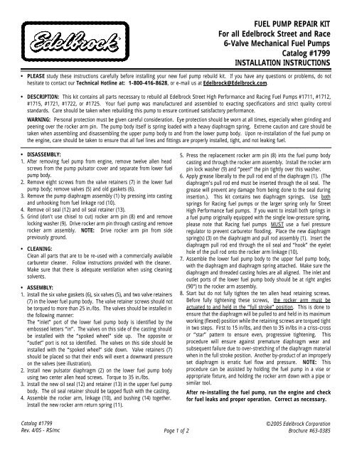
FUEL PUMP REPAIR KITFor all <strong>Edelbrock</strong> Street and Race6-<strong>Valve</strong> <strong>Mechanical</strong> <strong>Fuel</strong> <strong>Pump</strong>sCatalog #<strong>1799</strong>INSTALLATION INSTRUCTIONS• PLEASE study these instructions carefully be<strong>for</strong>e installing your new fuel pump rebuild kit. If you have any questions or problems, do nothesitate to contact our Technical Hotline at: 1-800-416-8628, or e-mail us at <strong>Edelbrock</strong>@<strong>Edelbrock</strong>.com.• DESCRIPTION: This kit contains all parts necessary to rebuild all <strong>Edelbrock</strong> Street High Per<strong>for</strong>mance and Racing <strong>Fuel</strong> <strong>Pump</strong>s #1711, #1712,#1715, #1721, #1722, or #1725. Your fuel pump was manufactured and assembled to exacting specifications and strict quality controlstandards. Care should be taken when rebuilding this pump to ensure continued satisfactory per<strong>for</strong>mance.WARNING: Personal protection must be given careful consideration. Eye protection should be worn at all times, especially when grinding andpeening over the rocker arm pin. The pump body itself is spring loaded with a heavy diaphragm spring. Extreme caution and care should betaken when assembling and disassembling the upper pump body to and from the lower pump body. Upon re-installation of the fuel pump onthe engine, care should be taken to ensure that all fuel lines and fittings are properly installed, tight, and not leaking fuel.• DISASSEMBLY:1. After removing fuel pump from engine, remove twelve allen headscrews from the pump pulsator cover and separate from lower fuelpump body.2. Remove eight screws from the valve retainers (7) in the lower fuelpump body; remove valves (5) and old gaskets (6).3. Remove the pump diaphragm assembly (1) by pressing into castingand unhooking from fuel linkage rod (10).4. Remove oil seal (12) and oil seal retainer (13).5. Grind (don’t use chisel to cut) rocker arm pin (8) end and removelocking washer (9). Drive rocker arm pin through casting and removerocker arm assembly. NOTE: Drive rocker arm pin from sidepreviously ground.• CLEANING:Clean all parts that are to be re-used with a commercially availablecarburetor cleaner. Follow instructions provided with the cleaner.Make sure that there is adequate ventilation when using cleaningsolvents.• ASSEMBLY:1. Install the six valve gaskets (6), six valves (5), and two valve retainers(7) in the lower fuel pump body. The valve retainer screws should notbe torqued to more than 25 in./lbs. The valves should be installed inthe following manner:The “inlet” port of the lower fuel pump body is identified by theembossed letters “in”. The valves on this side of the casting shouldbe installed with the “spoked wheel” side up. The opposite or“outlet” port is not so identified. The valves on this side should beinstalled with the “spoked wheel” side down. <strong>Valve</strong> retainers (7)should be placed so that their ends will exert a downward pressureon the valves (see illustration).2. Install new pulsator diaphragm (2) on the lower fuel pump bodyusing two center allen head screws. Torque to 35 in./lbs.3. Install the new oil seal (12) and retainer (13) in the upper fuel pumpbody. The oil seal retainer should be tapped flush with the casting.4. Assemble the rocker arm, linkage (10), and bushing (14) together.Install the new rocker arm return spring (11).5. Press the replacement rocker arm pin (8) into the fuel pump bodycasting and through the rocker arm assembly. Install the rocker armpin lock washer (9) and “peen” the pin tightly over this washer.6. Apply grease liberally to the pull rod end of the diaphragm (1). (Thediaphragm’s pull rod end must be inserted through the oil seal. Thegrease will prevent any damage from being done to the seal duringinsertion.). This kit contains two diaphragm springs. Use bothsprings <strong>for</strong> Racing fuel pumps or the larger spring only <strong>for</strong> StreetHigh Per<strong>for</strong>mance fuel pumps. If you want to install both springs ina fuel pump originally equipped with the single low-pressure spring,please note that Racing fuel pumps MUST use a fuel pressureregulator to prevent carburetor flooding. Place the new diaphragmspring(s) (3) on the diaphragm and pull rod assembly (1). Insert thediaphragm pull rod end through the oil seal and “hook” the eyelethole of the pull rod onto the rocker arm linkage (10).7. Assemble the lower fuel pump body to the upper fuel pump body,with the diaphragm and diaphragm spring attached. Make sure thediaphragm and threaded casting holes are all aligned. The inlet andoutlet ports of the lower fuel pump body should be at right angles(90°) to the rocker arm assembly.8. Start but do not fully tighten the ten allen head retaining screws.Be<strong>for</strong>e fully tightening these screws, the rocker arm must beactuated to and held in the “full stroke” position. This is done toensure that the diaphragm will be pulled to and held in its maximumworking (flexed) position while the retaining screws are torqued tightin two steps. First to 15 in/lbs, and then to 35 in/lbs in a criss-crossor “star” pattern to ensure even, progressive tightening. Thisprocedure will ensure against premature diaphragm wear andsubsequent failure due to over-stretching of the diaphragm materialwhen in the full stroke position. Another by-product of an improperlyset diaphragm is erratic fuel flow and pressure. NOTE: Thisprocedure can be assisted by holding the fuel pump in a vise orappropriate fixture, and holding the rocker arm down with a pipe orsimilar tool.After re-installing the fuel pump, run the engine and check<strong>for</strong> fuel leaks and proper operation. Correct as necessary.Catalog #<strong>1799</strong>Rev. 4/05 - RS/mc Page 1 of 2©2005 <strong>Edelbrock</strong> CorporationBrochure #63-0385
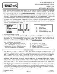
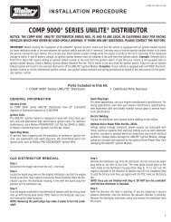
94EXPLODED VIEW OF EDELBROCK FUEL PUMPUpper <strong>Fuel</strong> <strong>Pump</strong> Body14Lower <strong>Fuel</strong> <strong>Pump</strong> Body1138In6101213Proper <strong>Valve</strong>Installation<strong>for</strong> “Outlet”Side of <strong>Pump</strong>5721Pulsator Cover(1) Diaphragm and Pull Rod Assembly(2) Pulsator Diaphragm(3) Diaphragm Spring(4) Mounting Gasket(5) <strong>Valve</strong>(6) <strong>Valve</strong> Gasket(7) <strong>Valve</strong> Retainer(8) Rocker Arm Pin(9) Rocket Arm Lockwasher(10) Rocker Arm Linkage(11) Rocker Arm Spring(12) Oil Seal(13) Oil Seal Retainer(14) Bushing<strong>Edelbrock</strong> Corporation • 2700 Cali<strong>for</strong>nia St. • Torrance, CA 90503Tech Line: 800-416-8628 • E-Mail: <strong>Edelbrock</strong>@<strong>Edelbrock</strong>.comCatalog #<strong>1799</strong>Rev. 4/05 - RS/mc Page 2 of 2©2005 <strong>Edelbrock</strong> CorporationBrochure #63-0385