PERFORMER RPM Camshaft/Lifters/Lube Kit ... - CatalogRack.com
PERFORMER RPM Camshaft/Lifters/Lube Kit ... - CatalogRack.com
PERFORMER RPM Camshaft/Lifters/Lube Kit ... - CatalogRack.com

Create successful ePaper yourself
Turn your PDF publications into a flip-book with our unique Google optimized e-Paper software.
<strong>PERFORMER</strong> <strong>RPM</strong><strong>Camshaft</strong>/<strong>Lifters</strong>/<strong>Lube</strong> <strong>Kit</strong>CATALOG #7122MODEL: 289-302 c.i.d. Ford V8 (not forBoss 302 or 1985 & later roller lifter engines)• PLEASE study these instructions carefully before installingyour new camshaft. If you have any questions or problems, donot hesitate to call our Technical Hotline at: 1-800-416-8628.• CAMSHAFT: Edelbrock Performer <strong>RPM</strong> camshafts are groundspecifically for use with the corresponding Performer <strong>RPM</strong>manifold. The Performer <strong>RPM</strong> manifold #7121, and Performer<strong>RPM</strong> camshaft #7122, are designed to work as a team to giveyou better driveability and performance. They are dyno-matchedand street-proven. For best results, use the Edelbrockmanifold/camshaft package with the carburetor and headers were<strong>com</strong>mend. The Performer <strong>RPM</strong> camshafts are designed for usewith modified or high performance cylinder heads and valvetrain <strong>com</strong>ponents only. Screw-in studs and H.P. adjustable rockerarms must be used.NOTE: Maximum performance is achieved only when theEdelbrock Performer <strong>RPM</strong> Power Package <strong>com</strong>ponents are usedwith the following equipment:• Performer <strong>RPM</strong> manifold/camshaft/timing set/valve springs• Performer Series carb #1405 (600 cfm) or #1407 (750 cfm)• fuel delivery system of sufficient capacity• 1-3/4" headers• aftermarket/re-curved distributors• IMPORTANT: This instruction sheet provides general installationguidelines which can affect your warranty. Read it carefully.It is not our intent to cover each detail of installation here; astep-by-step procedure manual would be far too lengthy. Wewant to caution you that installing a camshaft is a <strong>com</strong>plicatedprocedure that requires a good general knowledge of automotiveengines. If you are not confident that you can <strong>com</strong>plete thecamshaft installation successfully, we suggest you consider havingit installed by an experienced mechanic.CAUTION: Improper installation will result in LOWMILEAGE, POOR PERFORMANCE, COSTLY REIN-STALLATION, and ENGINE DAMAGE.TO AVOID THESE PROBLEMS YOU MUST DO THEFOLLOWING:Carefully study and understand all instructions.Examine the camshaft for possible shipping damage (ifdamaged contact you dealer immediately).PREPARATION CHECKLIST• TOOLS AND EQUIPMENTUse the following checklist for items needed.box and open-end wrenchessocket setdistributor wrenchpliers (channel locks & hose clamp)screw drivers (regular and phillips)torque wrenchhammergasket scraper or putty knifetiming lightvacuum gaugeragswater bucketharmonic balancer pullergear puller- for crankshaft sprocketHARDWARE & PARTS TO BUYgaskets- Fel-Pro #1250, OEM or equivalentpipe plugs, if neededEdelbrock Gasgacinch, #9300RTV Silicone Gasket Sealerchalkpaper and pencilradiator coolantteflon tapeEdelbrock Performer-Link True Rolling Timing Chain and GearSet #7811/#7820 or Accu-Drive Gear Drive #7892Edelbrock Sure Seat Valve Springs, #5722Manifold bolt kit #8524• INSTRUCTIONS FOR ENGINE PARTS REMOVAL BEFORE CAMSHAFT INSTALLATION1. Disconnect battery.2. For ease of installation, keep all parts in some sort of order.WARNING: Do not remove radiator cap or radiator hose ifengine is hot.3. Drain radiator coolant, move fan shroud back and remove fanand spacer from water pump. On air conditioned vehicles,remove bolt, lower idler pulley and <strong>com</strong>pressor-to- water pumpmount. Disconnect hoses and brackets. Most vehicles willrequire radiator removal prior to cam removal. Remove waterpump.4. Disconnect all linkage from carburetor such as throttle, throttlesprings, transmission, cruise control and automatic choke.5. Tag and remove vacuum lines.6. Remove valve covers.7. Remove distributor cap and wires, rotate engine until rotorpoints towards number 1 terminal in cap and pointer on frontcover is on Top Dead Center (TDC) and remove distributor.Note the approximate position of the vacuum advance canisterin relation to the manifold to assist in getting the distributorproperly located during re-installation.©1997 Edelbrock Corp. page 1Rev.1/97
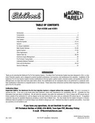
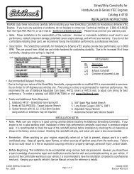
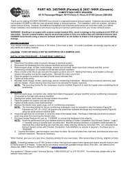
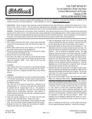
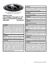
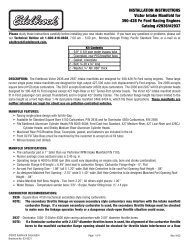
• CAMSHAFT/LIFTER RUN-INCAUTION: Change the engine oil and filter before start-up andagain after the initial break-in. Do not allow the engine to rununder 2000 rpm for the first 1/2 hour. Vary engine speedbetween 2000 and 3000 rpm. Slow idle speeds may result insevere cam and lifter wear.1. Start the engine and bring to break-in rpm.IMPORTANT INSTRUCTIONS AFFECTING YOUR WAR-RANTY• CAM LOBE WEAR- Cam lobe wear is almost non-existentunless mismatched parts are used or installation of the cam andlifters is done improperly. Most cam damage is caused by thetiming gear <strong>com</strong>ing loose due to improper torque on bolt. Boltsholding gear to camshaft should be torqued carefully and a locking<strong>com</strong>pound applied to threads of bolts.• CAM GEARS AND CAMSHAFT END PLAY- If cam gearbe<strong>com</strong>es loose, the cam will slide back in the block, causing thelifters to hit the lobes next to them and also the cam bearingjournals. If the engine is run after this happens, the bottom ofthe lifters and the sides of the lobes will be<strong>com</strong>e clipped.When installing a camshaft, it is always important to check forproper operating clearances, especially when high performance<strong>com</strong>ponents are used. Things to look for that can cause failureand damaged parts are as follows:1. Improper valve-to-piston clearance (this should be no less than0.080").2. Rocker arm stud slot clearance (both ends; valve closed andopen).3. Proper spring settings (see dimensions with spring instructionsheet; correct dimensions mean maximum performance andlonger engine life).• SPECIAL INSTRUCTIONSWith the Edelbrock manifold and camshaft package plus a headerinstallation, a carburetor jet change may be required for bestperformance. Due to the varied applications of year and modelof vehicles, no one <strong>com</strong>bination could suffice for all installations.The following procedure is only a guideline and in manycases, the manufacturing specifications for re<strong>com</strong>mended carburetorsor timing may be best.• IGNITION TIMINGIgnition timing for this package may vary with each application.A good starting figure would be between 10 degrees to 14degrees initial timing at idle with vacuum advance disconnected.Total advance should not exceed 32 degrees to 34 degrees withinitial and centrifugal weights <strong>com</strong>bined and should be at fulladvance at 3000-3500 rpm. After timing is adjusted, re-connectthe vacuum advance line. NOTE: The best <strong>com</strong>bination for anyparticular vehicle or application must be determined by trial anderror using the above information as a guideline.• HEADERSFor best performance, headers are re<strong>com</strong>mended. For this application,they should be 1-5/8" or 1-3/4" diameter, approximately31" long and terminating into a 3" collector. The remainder ofthe exhaust system should consist of dual exhaust and tail pipes,at least 2" diameter with low back-pressure mufflers.• WARNINGIn order for this Performer <strong>RPM</strong> cam and lifter kit to be coveredunder ANY WARRANTY you MUST use the correct EdelbrockSure Seat Valve Springs. The end flap or label from your SureSeat Valve Spring box must be sent in with your camshaft warrantycard.Failure to install new Edelbrock Sure Seat Valve Springs withyour new Performer <strong>RPM</strong> cam and lifter kit could cause the camlobes to wear excessively and could cause additional enginedamage. IF YOU HAVE ANY QUESTIONS ABOUT THISAPPLICATION, PLEASE CONTACT OUR TECHNICALDEPARTMENT IMMEDIATELY.• PLEASE <strong>com</strong>plete and mail your warranty card. Be sure towrite the model number of this product in the “Part #____”space.THANK YOU.Timing MarksTiming ChainSprocket AlignmentFigure 1• CAUTION: Use Edelbrock Performer-Plus Timing Chain andGear Set #7811/#7820 or Accu-Drive gear drive #7892. Do notuse late model timing chain and gear sets that are designed foremission-controlled engines. These timing sets are machined ina retarded position and are not re<strong>com</strong>mended for this camshaftinstallation. Edelbrock Timing Sets feature three keyways forspecific timing selection.page 3Figure 2Firing Order 1-5-4-2-6-3-7-8289-302 c.i.d. Ford V8Turn distributor clockwise to advance timing.NOTE: 5.0 Litre H.O. engines originally have a differentfiring order. This must be changed to the firing order listedabove when installing Performer <strong>RPM</strong> camshaft #7122.
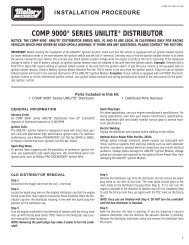
CAMSHAFT: Performer <strong>RPM</strong> HydraulicCATALOG #7122ENGINE: Ford 289-302 c.i.d. V8<strong>RPM</strong> RANGE: 1500-6500CAUTION: Do not use dual valve springs. Use onlyre<strong>com</strong>mended Edelbrock Sure Seat Valve Springs #5722.Use stock ratio (1.6:1) rocker arms only.CAMSHAFT: Performer <strong>RPM</strong> HydraulicCATALOG #7122ENGINE: Ford 289-302 c.i.d. V8<strong>RPM</strong> RANGE: 1500-6500CAUTION: Do not use dual valve springs. Use onlyre<strong>com</strong>mended Edelbrock Sure Seat Valve Springs #5722.Use stock ratio (1.6:1) rocker arms only.Duration at .004" Lift:Duration at .050" Lift:Intake 290Þ Exhaust 300ÞIntake 224Þ Exhaust 234ÞDuration at .004" Lift:Duration at .050" Lift:Intake 290Þ Exhaust 300ÞIntake 224Þ Exhaust 234ÞLift at cam: Intake .310" Exhaust .325"Lift at valve: Intake .496" Exhaust .520"Timing at .050 Lift:Open CloseIntake 5Þ BTDC 39Þ ABDCExhaust54Þ BBDC 0Þ ATDCCenterlines: Lobe Separation: 112°Intake Centerline: 107°• CAUTION: Use Edelbrock Performer-Plus Timing Chainand Steel Gear Set #7811/#7820 or Accu-Drive gear drive#7892. Do not use late model timing chain and gear sets thatare designed for emission-controlled engines. These timingsets are machined in a retarded position and are not re<strong>com</strong>mendedfor this camshaft installation. Edelbrock Timing Setsfeature three keyways for specified timing selection.Lift at cam: Intake .310" Exhaust .325"Lift at valve: Intake .496" Exhaust .520"Timing at .050 Lift:Open CloseIntake 5Þ BTDC 39Þ ABDCExhaust54Þ BBDC 0Þ ATDCCenterlines: Lobe Separation: 112°Intake Centerline: 107°• CAUTION: Use Edelbrock Performer-Plus Timing Chainand Steel Gear Set #7811/#7820 or Accu-Drive gear drive#7892. Do not use late model timing chain and gear sets thatare designed for emission-controlled engines. These timingsets are machined in a retarded position and are not re<strong>com</strong>mendedfor this camshaft installation. Edelbrock Timing Setsfeature three keyways for specified timing selection.CAMSHAFT: Performer <strong>RPM</strong> HydraulicCATALOG #7122ENGINE: Ford 289-302 c.i.d. V8<strong>RPM</strong> RANGE: 1500-6500CAUTION: Do not use dual valve springs. Use onlyre<strong>com</strong>mended Edelbrock Sure Seat Valve Springs #5722.Use stock ratio (1.6:1) rocker arms only.CAMSHAFT: Performer <strong>RPM</strong> HydraulicCATALOG #7122ENGINE: Ford 289-302 c.i.d. V8<strong>RPM</strong> RANGE: 1500-6500CAUTION: Do not use dual valve springs. Use onlyre<strong>com</strong>mended Edelbrock Sure Seat Valve Springs #5722.Use stock ratio (1.6:1) rocker arms only.Duration at .004" Lift:Duration at .050" Lift:Intake 290Þ Exhaust 300ÞIntake 224Þ Exhaust 234ÞDuration at .004" Lift:Duration at .050" Lift:Intake 290Þ Exhaust 300ÞIntake 224Þ Exhaust 234ÞLift at cam: Intake .310" Exhaust .325"Lift at valve: Intake .496" Exhaust .520"Timing at .050 Lift:Open CloseIntake 5Þ BTDC 39Þ ABDCExhaust54Þ BBDC 0Þ ATDCCenterlines: Lobe Separation: 112°Intake Centerline: 107°• CAUTION: Use Edelbrock Performer-Plus Timing Chainand Steel Gear Set #7811/#7820 or Accu-Drive gear drive#7892. Do not use late model timing chain and gear sets thatare designed for emission-controlled engines. These timingsets are machined in a retarded position and are not re<strong>com</strong>mendedfor this camshaft installation. Edelbrock Timing Setsfeature three keyways for specified timing selection.Lift at cam: Intake .310" Exhaust .325"Lift at valve: Intake .496" Exhaust .520"Timing at .050 Lift:Open CloseIntake 5Þ BTDC 39Þ ABDCExhaust54Þ BBDC 0Þ ATDCCenterlines: Lobe Separation: 112°Intake Centerline: 107°• CAUTION: Use Edelbrock Performer-Plus Timing Chainand Steel Gear Set #7811/#7820 or Accu-Drive gear drive#7892. Do not use late model timing chain and gear sets thatare designed for emission-controlled engines. These timingsets are machined in a retarded position and are not re<strong>com</strong>mendedfor this camshaft installation. Edelbrock Timing Setsfeature three keyways for specified timing selection.