Flystick-3_QuickGuid.. - Schneider Digital
Flystick-3_QuickGuid.. - Schneider Digital
Flystick-3_QuickGuid.. - Schneider Digital
- No tags were found...

You also want an ePaper? Increase the reach of your titles
YUMPU automatically turns print PDFs into web optimized ePapers that Google loves.
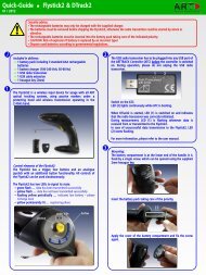
Quick-Guide 01 / 2012<strong>Flystick</strong>3 & DTrack2Security advice:The rechargeable batteries may only be charged with the supplied charger.Before shipping the <strong>Flystick</strong>3 by mail or air transport the batteries must be taken out, otherwise the radio transmitter couldbe started by shock or vibration.CAUTION: Risk of explosion if battery is replaced by an incorrect type!Dispose used batteries according to governmental regulations.iIncluded in delivery:✔ 1 battery pack✔ 1 battery charger (100-240 Volt, 50-60 Hz)✔ 1 charging unit✔ 1 USB radio transceiver✔ 1 USB cable extension✔ 1 hexagon key (2.5mm)3The USB radio transceiver has to be plugged into any USB portof the ARTTRACK Controller (ATC) before the controller isswitched on. During operation, please do not unplug the USBradio transceiver.121The <strong>Flystick</strong>3 is a wireless input device for usage with all ARToptical tracking systems, using active or passive markers andwireless transmission operating in the 2.4GHz band.Switch on the ATC.LED (2) lights continuously while ATC is booting.When DTrack2 is started, LED (1) is switched on and indicatesthat the radio transceiver was correctly initialized.During measurement, LED (1) is flashing whenever data isreceived from or transmitted to the <strong>Flystick</strong>3.In case of unsuccessful data transmission to the <strong>Flystick</strong>3, LED(2) starts flashing.Control elements of the <strong>Flystick</strong>3:The <strong>Flystick</strong>3 is equipped with a trigger, three buttons and ananalogue joystick for wireless and simultaneous interaction in avirtual environment. Synchronization of the active target isprovided wirelessly with a modulated flash by one camera.4Mounting:For inserting the battery into the <strong>Flystick</strong>3, you have to take offthe back cover completely. Therefore, loosen the four screwsusing the 2.5mm hexagon key.Remove the back cover.The <strong>Flystick</strong>3 has two status LEDs to signal its state:● green pulse … data has been transmitted successfully● yellow pulse … data has not been transmitted successfully● yellow flash … indicates low battery – please recharge soon2Charging the <strong>Flystick</strong>3:Place the <strong>Flystick</strong>3 in the charging unit and plug in the batterycharger in the charging jack on the front of the charging unit.Place the battery correctly within the cut-out.Apply the back cover again and tighten the screws.charging jackcharging unitThe status LEDs of the <strong>Flystick</strong>3 will indicate the chargingstatus.21
Quick-Guide <strong>Flystick</strong>3 & DTrack25When using the <strong>Flystick</strong>3 with active target, the modulated flashhas to be activated in “Settings” → “Cameras” → “Advanced”for one camera. This camera has to be in syncgroup #1.<strong>Flystick</strong> configuration:Select “Settings” → “<strong>Flystick</strong>” and the configuration window isopened. Define the desired number of <strong>Flystick</strong>s to be used.7Body calibration:If the <strong>Flystick</strong>3 has been recognized correctly in step 4 pleaseselect “Calibration” → “Body”.In the appearing dialogue, the body to be selected is named“<strong>Flystick</strong> body 01”. Please define the orientation of the bodycoordinate system relative to the body (default setting is due tobody). Make sure that all markers (depending on the target: fouror five) of the <strong>Flystick</strong>3 are seen by the cameras using the“Monitor 2DOF” view which appears in the background.You have to assign your <strong>Flystick</strong>3 to a '<strong>Flystick</strong> ID' by selecting'F1' and selecting your <strong>Flystick</strong>3 out of the “available <strong>Flystick</strong>s”list.If the list “available <strong>Flystick</strong>s” doesn't contain your <strong>Flystick</strong>3(represented by its serial number) although it is already present,just press a button of the <strong>Flystick</strong>3 to register it at the radiotransceiver. Press “Select” and “OK”.Press “Calibrate” → the calibration starts within 5 seconds.➢ NOTE: The radio transmission and the active target areswitched off after 15 minutes without usage. Press any buttonto reactivate the <strong>Flystick</strong>3 and, therefore, tracking.Depending on the ATC, there are two <strong>Flystick</strong>1 entries in the list“available <strong>Flystick</strong>s“, even if no <strong>Flystick</strong>1 is present in thevolume. This is due to the fact that the <strong>Flystick</strong>1 connects viaserial COM-port which cannot be polled automatically. If you areusing a <strong>Flystick</strong>1 please refer to the <strong>Flystick</strong>1 manual.8Display Data:During DTrack measurement the 6DOF results of the tracked<strong>Flystick</strong>3 are listed among the other calibrated bodies in theDisplay Data window.Select “Display” → “<strong>Flystick</strong>” to see which <strong>Flystick</strong>3 buttons arecurrently pressed by the user.These are indicated by blue fields in the corresponding column.The <strong>Flystick</strong>3 with active target emits IR flashes either in onesingle, two or three sync groups (adjustable) depending on yoursetup. Depending on the distance (close / far) between <strong>Flystick</strong>3and cameras the flash intensity (1 / 4) of the <strong>Flystick</strong>3 target isadjustable. The highest flash intensity results in higher powerconsumption.Ticking the checkbox “use 6DOF filter” applies a filter to themeasurement data in order to remove the jitter of the positionmeasurement. If your application has been configured to use theoutput format of the <strong>Flystick</strong>1, you can simply tick the checkbox“use old output format” in order to be compatible. Using theold output format will automatically change the analoguejoystick to digital.9Output settings:In DTrack2, select “Settings“ → “Output“. You can either select“this computer” (remote PC) or enter an IP address of thecomputer you want to send data to.Please make sure that the checkbox for <strong>Flystick</strong> data is ticked.Otherwise, the data will not be transmitted.Press “Start” to start measurement.For more details on the <strong>Flystick</strong>3, please refer to the manual.6MultiUser option (if more than one <strong>Flystick</strong> is used):The MultiUser option is an enhancement especially for VR / ARapplications when working with more than one <strong>Flystick</strong>. Up toten users can be equipped with a <strong>Flystick</strong> and a head target(usually mounted on glasses). The software DTrack2 tracks themall, but only transmits the data pair (<strong>Flystick</strong> and head body) ofone user. Switching between the single users can be done by justpressing one of the <strong>Flystick</strong> buttons.The MultiUser option is available as additional license forDTrack2 if two or more (max. 10) <strong>Flystick</strong>s are participating inthe entire tracking system.iPlease refer to the user manual for a more detailed descriptionof the ART tracking system. If you need further assistance pleasedo not hesitate to contact our support:ART GmbH +49 (0)881-92530-00http://www.ar-tracking.de© Copyright 2012 ART GmbH