3202 Rev A Module Specifications - Advanced Micro Controls Inc
3202 Rev A Module Specifications - Advanced Micro Controls Inc
3202 Rev A Module Specifications - Advanced Micro Controls Inc

You also want an ePaper? Increase the reach of your titles
YUMPU automatically turns print PDFs into web optimized ePapers that Google loves.
<strong>3202</strong> <strong>Rev</strong> A <strong>Module</strong> <strong>Specifications</strong>Two Channel ControlLogix Stepper <strong>Module</strong><strong>Rev</strong>ision 4.0The <strong>3202</strong> module is a two-axis stepper controller that occupies one slot in a ControlLogix rack. This unitreceives profile data from the PLC and outputs Step and Direction signals or Clockwise/CounterClockwise pulses to a stepper driver. Inputs on the module allow homing and emergency stop operations.Differential incremental encoders can be attached to the unit to provide feedback information.The <strong>3202</strong> uses sixteen 32 bit input words and sixteen 32 bit output words. The two channels are totallyindependent from each other and can be configured and programmed to perform different operations.Because the <strong>3202</strong> module does not use a non-volatile memory, it must be configured at every power up.Sample programs showing how to program the <strong>3202</strong> module are available from the following page of ourwebsite.http://www.amci.com/sampleprograms.asp20 Gear Drive, Plymouth Industrial Park, Terryville, CT 06786 page: 1Tel: (860) 585-1254 Fax: (860)584-1973 E-mail: Sales @amci.com
<strong>3202</strong> <strong>Rev</strong> A <strong>Module</strong> <strong>Specifications</strong>Two Channel ControlLogix Stepper <strong>Module</strong><strong>Rev</strong>ision 4.0Table of ContentsInstalling the <strong>3202</strong> <strong>Module</strong> Chapter 1 4Installing the <strong>3202</strong> module 4Configuring a ControlLogix system 4<strong>Module</strong> <strong>Specifications</strong> 5Discrete Input <strong>Specifications</strong> 6Front Panel & LED Functions 7Output Signals 7Connector Pinout and Wiring Notes 8Diagnostic Feedback Wiring 9Differential Output Wiring 9Single Ended Encoder Wiring 10Calculating Move Profiles Chapter 2 11Configuration Programming Chapter 3 13Configuration Bits 15Input Active Level 15Starting Speed 16Invalid Configurations 16Configuration Mode Input Data 17Command Mode Operations Chapter 4 18Absolute & Relative Moves 18Hold Move 19Resume Move 19Immediate Stop 19Find Home +/(CW), Find Home -/(CCW) 20Manual Move +/(CW), Manual 23Move -/(CCW)Preset Current Position 24Preset Encoder Position 24Reset Errors 24Blend Move 25Encoder Move 26Diagnostic Feedback 26Acceleration Types 27Command Mode Output Data Chapter 5 28Command Words 28Command Bits 29Blend Move Programming (message instructions) 30Command Mode Input Data Chapter 6 33Status Bits 33Input Word Functions 34Status & Error Bit Functions 35<strong>Rev</strong>ision History 3820 Gear Drive, Plymouth Industrial Park, Terryville, CT 06786 page: 3Tel: (860) 585-1254 Fax: (860)584-1973 E-mail: Sales @amci.com
Chapter 1: Installing the <strong>3202</strong> module<strong>3202</strong> <strong>Rev</strong> A <strong>Module</strong> <strong>Specifications</strong>Two Channel ControlLogix Stepper <strong>Module</strong><strong>Rev</strong>ision 4.0The <strong>3202</strong> can be installed in any ControlLogix module slot as long as power supply requirements are met.The <strong>3202</strong> module requires 510mA from the 5Vdc supply to operate.1. Align the module’s circuit board with the top and bottom card guides in the rack.2. Gently slide the module into the rack until the top and bottom latches secure the module in place.To remove the module, depress the top and bottom latches and slide the module out of the rack.Note The ControlLogix backplane is hot-swappable. That is, the <strong>3202</strong> module can be inserted andremoved under power.Configuring the ControlLogix system for the <strong>3202</strong> module1. Open RSLogix 5000 and the project in which you want to install the AMCI <strong>3202</strong> module.2. Right click on I/O Configuration in the Project Tree.3. Select New <strong>Module</strong>.4. Select the following module type and description from the list that appears.Type = 1756-MODULEDescription = Generic 1756 <strong>Module</strong> (This module will appear as an Unknown Device when viewedfrom RSNetworx)Click on OK.5. Enter the following module properties.Name: Your Choice (must begin with a letter)Description: Your ChoiceComm Format: Data-DINT (must be Data-DINT)Slot: location of <strong>3202</strong> module6. Enter the Connection Parameters from the following table. (The Listen Only columns will only beused by any additional processors that are installed in the rack chassis.)CONNECTION PARAMETERSOwner ControllerListen OnlyAssemblyInstanceSize in 32bit wordsAssemblyInstanceSize in 32bit wordsINPUT 100 16 101 16OUTPUT 194 16 195 1CONFIGURATION 242 0 2 07. Click on Next >8. Set the RPI (Rate Packet Interval) Time to the desired value. 5ms is the recommended value. Theminimum RPI is 0.5ms. However, below 3ms, the unit may occasionally lose communication withthe PLC.9. Click on Finish >>20 Gear Drive, Plymouth Industrial Park, Terryville, CT 06786 page: 4Tel: (860) 585-1254 Fax: (860)584-1973 E-mail: Sales @amci.com
<strong>3202</strong> <strong>Rev</strong> A <strong>Module</strong> <strong>Specifications</strong>Two Channel ControlLogix Stepper <strong>Module</strong><strong>Rev</strong>ision 4.0Discrete Inputs• Input Type: Sinking• Input Voltage Range: On = 8 to 24VdcOff = 0 to 2Vdc• Input Current: 15mA @ 24Vdc• Response Time (On and Off): 5µs• The module interrogates the Discrete Inputs a maximum of every 250µs.• The Input Functions are described belowCapture InputWith version 3.1 or later firmware, the inactive to active transition of this input will cause either thecurrent encoder data or the current position data to be captured and placed in the input registers. Withversion 2.2 or earlier firmware, only the current encoder can be captured. In either case, this valuewill remain until the next inactive to active transition of the input.External InputWhen this input becomes active during a move operation, the stepper motor will decelerate and stop,while keeping track of the current position. During a Manual Move, the External Input will initiate acontrolled stop. During an Absolute or Relative move, the External Input will cause the module to make acontrolled stop to a hold state.If the External Input is active when a move operation is initiated, the <strong>3202</strong> module will generate only onestep in the specified direction.Emergency StopThe Emergency Stop Input causes the current move operation to stop without any deceleration. Thepulse signal is simply stopped. If the channel was moving when this command was issued, thecurrent position will become invalid, and the Position Invalid Input Bit will be set. The channel willhave to be Preset or Homed again before an Absolute Move operation can be performed. However, itwill be possible to perform a Relative or a Manual Move after the Emergency Stop Input has beenused.Home InputReaching the Home Input during a homing operation will cause the <strong>3202</strong> module to reset both theCurrent Position, and if applicable the Encoder Position, to zero. The Home Input has no functionunless a homing operation is being performed.Each channel of the <strong>3202</strong> module must be configured with the ability to home the module. This istrue even if your system does not require a Home Input.CW & CCW Limit Switch InputsDuring most move operations, the CW and CCW Limit Switches act as an Emergency Stop input.There are two exceptions. The first is during a homing operation, where the direction of motion willbe reversed and the module will start looking for the Home Input in the opposite direction. Thesecond is if the opposite end limit switch is reached during a Manual Move operation. For example ifthe CW limit switch is reached during a CCW Manual Move. In this case the module will ignore theEnd Limit Switch input.Each channel of the <strong>3202</strong> module must be configured with at least one of these Limit Switch Inputs.20 Gear Drive, Plymouth Industrial Park, Terryville, CT 06786 page: 6Tel: (860) 585-1254 Fax: (860)584-1973 E-mail: Sales @amci.com
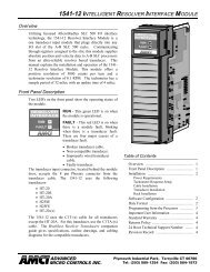
<strong>3202</strong> <strong>Rev</strong> A <strong>Module</strong> <strong>Specifications</strong>Two Channel ControlLogix Stepper <strong>Module</strong><strong>Rev</strong>ision 4.0Front PanelLED FunctionStatus LED (Listed by priority)Solid Red: <strong>Module</strong> failed power up diagnosticsBlinking Red: Configuration Error, Command Error, InputError, Home Invalid Error, or an Invalid ProfileError. Set when error detected on either channel.Blinking Green: Motion on either channelSolid Green: <strong>Module</strong> OK, no motion in progress, at least onechannel configuredOff: Both channels disabledOK LEDSolid Red: <strong>Module</strong> FaultBlinking Red: Communication between module and PLCinterruptedBlinking Green: PLC is in Program Mode or one waycommunication, module only sends data to thePLC, or slot is not correctly configured for themoduleSolid Green: <strong>Module</strong> Owned, two way communicationOutput SignalsThe <strong>3202</strong> module can be programmed to output either Step and Direction signals or CW / CCW steps.There is no advantage to either type; you must simply configure each channel of the <strong>3202</strong> module tomatch the input type of your driver. The two signals types are illustrated below.Step and Direction OutputStep OutputDirection OutputCW Motion or <strong>Inc</strong>reasing CountsCCW Motion or Decreasing CountsCW and CCW Step OutputsCW Output<strong>Inc</strong>reasing CountsCCW OutputDecreasing Counts20 Gear Drive, Plymouth Industrial Park, Terryville, CT 06786 page: 7Tel: (860) 585-1254 Fax: (860)584-1973 E-mail: Sales @amci.com
<strong>3202</strong> <strong>Rev</strong> A <strong>Module</strong> <strong>Specifications</strong>Two Channel ControlLogix Stepper <strong>Module</strong><strong>Rev</strong>ision 4.0Connector Pin Out:The input connector consists of a Removable Terminal Block with the Rockwell Automation Part Numbers1756-TBCH (36 position cage clamp) or 1756-TBS6H (36 position spring clamp). The terminal block isnot supplied with the <strong>3202</strong> module.Channel 1 +A Encoder Input21Channel 2 +A Encoder InputChannel 1 –A Encoder Input43Channel 2 –A Encoder InputChannel 1 +B Encoder Input65Channel 2 +B Encoder InputChannel 1 –B Encoder Input87Channel 2 –B Encoder InputChannel 1 +Z Encoder Input109Channel 2 +Z Encoder InputChannel 1 –Z Encoder Input1211Channel 2 –Z Encoder InputChassis Ground (shields)1413Chassis Ground (shields)Channel 1 +Step or +CW Output1615Channel 2 +Step or +CW OutputChannel 1 –Step or –CW Output1817Channel 2 –Step or –CW OutputChannel 1 +Dir. or +CCW Output2019Channel 2 +Dir. or +CCW OutputChannel 1 –Dir. or –CCW Output2221Channel 2 –Dir. or –CCW OutputChannel 1 Capture Input2423Channel 2 Capture InputChannel 1 External Input2625Channel 2 External InputChannel 1 Home Input2827Channel 2 Home InputChannel 1 Emergency Stop Input3029Channel 2 Emergency Stop InputChannel 1 CW Limit Switch3231Channel 2 CW Limit SwitchChannel 1 CCW Limit Switch3433Channel 2 CCW Limit Switch<strong>Module</strong> Common3635<strong>Module</strong> CommonWiring Notes• The <strong>3202</strong> module uses a DS26LS31 differential line driver in series with a 10Ω resistor for the stepper (+/-step and +/- direction) outputs.• Stepper signals are generally low voltage, low power signals. If you are using A-B guidelines for cablinginstallation, treat the cable as a Category 2 cable. It can be installed in conduit along with other low powercabling such as communication cables and low power ac/dc I/O lines. It cannot be installed in conduit with acpower lines or high power ac/dc I/O lines.• To reduce or eliminate the influence of electrical noise on the system, the step and direction cable shieldsmust be connected to chassis ground terminals 13 or 14. Also, the shields must be connected to only one endof the cable run and treated as conductors at any junctions. Do not ground the shields at the junction box.• If the signal cable must cross power feed lines, it should do so at right angles.• Route the cable at least five feet from high voltage enclosures, or sources of “rf” radiation.• The <strong>Module</strong> Common terminals must be connected to the COM of the supply that powers the discrete inputs.A Stepper Driver with Single Ended Step and Direction inputs can also be referenced here.• The Chassis Ground pin is connected to the PLC’s chassis ground.20 Gear Drive, Plymouth Industrial Park, Terryville, CT 06786 page: 8Tel: (860) 585-1254 Fax: (860)584-1973 E-mail: Sales @amci.com
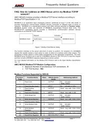
<strong>3202</strong> <strong>Rev</strong> A <strong>Module</strong> <strong>Specifications</strong>Two Channel ControlLogix Stepper <strong>Module</strong><strong>Rev</strong>ision 4.0Diagnostic Feedback WiringPin Numbers Signal Names16 to 2 +Step to +AChannel 1 18 to 4 - Step to -A20 to 6 +Direction to +B22 to 8 -Direction to -B15 to 1 +Step to +AChannel 2 17 to 3 - Step to -A19 to 5 +Direction to +B21 to 7 -Direction to -BDifferential Wiring DiagramThe pulse and direction cable shields must beconnected to chassis ground input pins 13 and 1420 Gear Drive, Plymouth Industrial Park, Terryville, CT 06786 page: 9Tel: (860) 585-1254 Fax: (860)584-1973 E-mail: Sales @amci.com
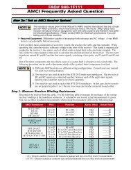
<strong>3202</strong> <strong>Rev</strong> A <strong>Module</strong> <strong>Specifications</strong>Two Channel ControlLogix Stepper <strong>Module</strong><strong>Rev</strong>ision 4.0Single Ended Encoder WiringThe <strong>3202</strong> module is designed to work with +5Vdc differential encoders. Use the following table anddiagrams to attach single ended encoders to the <strong>3202</strong> module. A current limiting resistor RLim must beinstalled for encoders that do not operate at 5Vdc.RLim<strong>3202</strong> module Sourcing Output Encoder+ A, B, or Z inputs- A, B, or Z inputsEncoder OutputEncoder Power Supply Common<strong>3202</strong> module Sinking Output Encoder+ A, B, or Z inputsEncoder Power Supply- A, B, or Z inputsEncoder OutputRLimEncoder PowerSupply5Vdc12Vdc15Vdc24VdcCurrent LimitingResistor RLimnone1KΩ1.2KΩ2.7KΩ20 Gear Drive, Plymouth Industrial Park, Terryville, CT 06786 page: 10Tel: (860) 585-1254 Fax: (860)584-1973 E-mail: Sales @amci.com
Chapter 2: Calculating Move Profiles<strong>3202</strong> <strong>Rev</strong> A <strong>Module</strong> <strong>Specifications</strong>Two Channel ControlLogix Stepper <strong>Module</strong><strong>Rev</strong>ision 4.0Before starting a move operation, the <strong>3202</strong> module completely calculates each portion of the moveprofile. That is, it calculates how many steps of the move profile will be required for acceleration andhow many steps will be required for deceleration. Depending on the data used to define the move profile,this can result in two types of velocity profiles, either a Trapezoidal Profile or a Triangular Profile.A Trapezoidal Profile jumps from rest to the Starting Speed, accelerates to the Programmed Velocity atthe commanded acceleration rate, continues at the Programmed Velocity to a predetermined point, andthen decelerates to the target position at the commanded deceleration rate to the starting speed and stops.VelocityStartingSpeedTrapezoidal ProfileHowever, if the length of a commanded move is not long enough to attain the programmed velocitybefore the deceleration point is reached, a Triangular Velocity profile will be generated.TimeVelocityStartingSpeedTriangular ProfileRegardless of the type of Velocity Profile that is being run, the following equations can be used todetermine both the time to accelerate and the number of steps needed to accelerate. These formulas canalso be used to calculate the time and distance to decelerate.TimeTa = (Vs – Vo)/aDa = Ta * (Vo + Vs)/2VelocityVsVo = Starting Speed (steps/second)Vs = Programmed Speed (steps/second)Ta = Time to accelerate (seconds)Da = Distance to accelerate (steps)a = Acceleration rate (steps/second/second)VoTime20 Gear Drive, Plymouth Industrial Park, Terryville, CT 06786 page: 11Tel: (860) 585-1254 Fax: (860)584-1973 E-mail: Sales @amci.com
<strong>3202</strong> <strong>Rev</strong> A <strong>Module</strong> <strong>Specifications</strong>Two Channel ControlLogix Stepper <strong>Module</strong><strong>Rev</strong>ision 4.0Calculation Notes1. The acceleration and deceleration values sent to the <strong>3202</strong> module as part of the move profile haveunits of steps/second/second.2. The acceleration and deceleration values have a minimum value of 1,000 steps/second/secondand a maximum of 2,000,000 steps/second/second.3. If the number of steps to accelerate plus the number of steps to decelerate is greater than thenumber of steps programmed in the target position registers, than the <strong>3202</strong> module will run aTriangular Velocity Profile.4. If the number of steps to accelerate plus the number of steps to decelerate is less than the numberof steps programmed in the target position, than the <strong>3202</strong> module will run a Trapezoidal VelocityProfile.VelocityVsStartingSpeedDa Ds DdTtDs = (Total Number of Steps) – (Da + Dd)Tt = Ta + Td + Ds/VsDa = Distance to Accelerate (steps)Ds = Distance at the programmed speed (steps)Dd = Distance to decelerate (steps)Vs = Programmed Speed (steps/sec)Tt = Total Profile Time (seconds)Starting SpeedThe starting speed has a range of 1 to 1,000,000 pulses/sec and is the pulse frequency at which everymove begins and ends. That is, the first and last pulses of the move profile will be at the starting speed.Some portions of the homing operations are also performed at the starting speed.The Starting Speed can be any value less than or equal to the programmed speed of the slowest move.Although it is not necessary, the smoothest transition from rest to the programmed speed will be achievedwith a Starting Speed equal to the square root of the acceleration value.You may have the starting speed set to too small a value if you have a larger than expected delay betweentwo of your move operations. For example, a starting speed of 1 step per second will result in a 1 seconddelay between move operations.20 Gear Drive, Plymouth Industrial Park, Terryville, CT 06786 page: 12Tel: (860) 585-1254 Fax: (860)584-1973 E-mail: Sales @amci.com
Chapter 3: Configuration Programming<strong>3202</strong> <strong>Rev</strong> A <strong>Module</strong> <strong>Specifications</strong>Two Channel ControlLogix Stepper <strong>Module</strong><strong>Rev</strong>ision 4.0The Configuration Mode provides the ability to select the proper setup configuration to match the stepperapplication without having to set any switches. The configuration file, consisting of two 32 bit words oneach channel, allows the following parameters to be defined.1. If a CW Limit Switch will be used and its input active state2. If a CCW Limit Switch will be used and its input active state3. If an Emergency Stop will be used and its input active state.4. If an External Input will be used and its active state.The External Input can be used to stop a Manual Move operation, or to place an Absolute or Relativemove in a hold state.If the External Input is active when a move operation is initiated, the <strong>3202</strong> module will generate only onestep in the specified direction.5. If the Capture Input will be used and its active state.6. If a Home Limit Switch will be used and its input active state.7. If a Quadrature Encoder will be used with the system8. If the channel will be configured for Diagnostic Feedback. Diagnostic Feedback allows the unit tocount its own output pulses by wiring the outputs to the encoder inputs.9. The output type, either CW and CCW Pulses or Pulse and Direction.10. The type of homing operation that will be performed. There are four Homing possibilities.1. Home Limit Switch Only2. Home Limit Switch with a backplane bit acting as a Home Proximity.3. Marker Pulse Home with the Home Limit Switch Input acting as a Home Proximity.4. Marker Pulse Home with a backplane bit acting as a Home Proximity.Note 1: When configured to use a Proximity Input, the <strong>3202</strong> module will ignoreany other home inputs until the proximity input is detected.Note 2: The Backplane Proximity bit is a set by the PLC to indicate to the <strong>3202</strong>module that you are nearing the location of either the Home Limit Switchor the encoder’s Marker Pulse.Note 3: The Marker Pulse option also requires the presence of the QuadratureEncoder.11. The Starting Speed. The starting speed is the pulse frequency that every move begins and ends at.Some portions of the homing operations are also performed at the starting speed.20 Gear Drive, Plymouth Industrial Park, Terryville, CT 06786 page: 13Tel: (860) 585-1254 Fax: (860)584-1973 E-mail: Sales @amci.com
<strong>3202</strong> <strong>Rev</strong> A <strong>Module</strong> <strong>Specifications</strong>Two Channel ControlLogix Stepper <strong>Module</strong><strong>Rev</strong>ision 4.0Configuration Mode Consumed Data (Sixteen 32 bit words sent from the PLC to the <strong>3202</strong> module)While in configuration mode, the output registers have the following format.32 bit outputConfigurationChannelWordOutput DataUnitsRange0 1 Configuration Bits See description below1 1 Starting Speed Steps / Second 1 to 1,000,0002 1 0 Must be zero3 1 0 Must be zero4 1 0 Must be zero5 1 0 Must be zero6 1 0 Must be zero7 1 0 Must be zero8 2 Configuration Bits See description below9 2 Starting Speed Steps / Second 1 to 1,000,00010 2 0 Must be zero11 2 0 Must be zero12 2 0 Must be zero13 2 0 Must be zero14 2 0 Must be zero15 2 0 Must be zeroNote 1: At power up, both channels will be disabled. They will remain disabled as long as configurationdata is not written to the module.Note 2: If Configuration Mode is entered while a move is occurring, the Command Error bit will be set,the move will run to completion, and then the module will enter Configuration Mode.20 Gear Drive, Plymouth Industrial Park, Terryville, CT 06786 page: 14Tel: (860) 585-1254 Fax: (860)584-1973 E-mail: Sales @amci.com
<strong>3202</strong> <strong>Rev</strong> A <strong>Module</strong> <strong>Specifications</strong>Two Channel ControlLogix Stepper <strong>Module</strong><strong>Rev</strong>ision 4.0Configuration BitsBit 0: set when the Capture Input will be used. With version 3.1 or higher firmware, the CaptureInput can be used in two ways.1. Using the Capture Input without the Quadrature Encoder will capture the Current PositionData.2. Using the Capture Input with the Quadrature Encoder will capture the Encoder Data.Bit 1: set when an External Input is used. The external input can be used to stop a Manual Moveoperation, or to place an Absolute or Relative move in a hold state.Bit 2: set when a Home Limit Switch Input will be used.Bit 3: set when the Emergency Stop Input will be usedBit 4: set when a CW Limit Switch will be usedBit 5: set when a CCW Limit Switch will be usedEven if they are not required by your application, the ability to home the module and at leastone end limit switch must exist in the configuration data. If this is true in your system, setbits 2, 4, 5,18, 20, and 21. This configures the module for all of the inputs and sets theactive state to active high. Simply do not wire anything to the input terminals and the inputswill be ignored.Bit 6: set for backplane Home Proximity operationsBit 7: reserved for future useBit 8: set when Quadrature encoder will be usedBit 9: set when diagnostic feedback will be usedBit 10: “1” when output pulse type is pulse train and direction“0” when output pulse type is CW pulse train and CCW pulse trainBit 11: reserved for future useBit 12: “0” for limit switch home operations“1” for marker pulse home operationsBits 13 to15: reserved for future useBit 16: determines the active level of the Capture InputBit 17: determines the active level of the External inputBit 18: determines the active level of the Home Limit Switch inputBit 19: determines the active level of the Emergency Stop inputBit 20: determines the active level of the CW Limit SwitchBit 21: determines the active level of the CCW Limit SwitchBits 22 to 27: Reserved for future useBit 28: Set to disable the channelBits 29 and 30: Reserved for future useBit 31: “1” for configuration mode operations, “0” for command mode operationsInput Active LevelDefines the active level of the inputs. These bits will be set for high level active or Normally Open (NO),or reset for low level active or Normally Closed (NC). Please note that the active level of the inputs istaken into account only when the input has been defined as being used.20 Gear Drive, Plymouth Industrial Park, Terryville, CT 06786 page: 15Tel: (860) 585-1254 Fax: (860)584-1973 E-mail: Sales @amci.com
<strong>3202</strong> <strong>Rev</strong> A <strong>Module</strong> <strong>Specifications</strong>Two Channel ControlLogix Stepper <strong>Module</strong><strong>Rev</strong>ision 4.0Starting SpeedThe starting speed has a range of 1 to 1,000,000 pulses/sec and is the pulse frequency at which everymove begins and ends. Some portions of the homing operations are also performed at the starting speed.Note: The Starting Speed can be any value less than or equal to the programmed speed of theslowest move. Although it is not necessary, the smoothest transition from rest to theprogrammed speed will be achieved with a Starting Speed equal to the square root of theacceleration value.You may have the starting speed set to too small a value if you have a larger than expecteddelay between two of your move operations. For example, a starting speed of 1 step persecond will result in a 1 second delay between move operations.Invalid ConfigurationsThe <strong>3202</strong> module will not accept all possible configurations. The following is a list of the invalidconfigurations:1. A configuration without the ability to home the module.2. A configuration without at least one End Limit Switch, either CW or CCW.Note: The ability to home the module and at least one of the end limit switches have to beconfigured. They do not have to actually be used in the stepper application.3. Using Quadrature Encoder and Diagnostic Feedback.4. Using a Marker Pulse Home without the Quadrature Encoder.5. Diagnostic Feedback with CW and CCW pulse outputs.6. A starting speed outside the range of 1 < starting speed < 1,000,000.7. Setting the module to use the Capture Input without configuring the module to use the encoder.(Firmware versions 2.2 or lower. Firmware versions 3.1 or higher do not have this restriction.)8. Setting any of the unused bits in the configuration words.9. Selecting Marker Pulse home without also selecting to use either the Home Input, which will actas a proximity limit, or the Backplane Proximity bit.10. Selecting Marker Pulse home with both the Home Input and the Backplane Proximity bit.11. Setting any of the unused words to a value other than zero.The <strong>3202</strong> has to be configured before starting any operations. When the Configuration Mode bit is set inthe output registers, the stepper controller enters Configuration Mode. When in this mode, the steppercontroller will stop its operations and set the Configuration Mode status bit in the input registers. It thenwaits for the configuration file to be transferred. If there is no current Configuration File present or if thetransferred Configuration File is not valid, the Configuration Error Input bit will be set. If the transferredconfiguration file is accepted, and if it is different from the current configuration, the configuration datawill be mirrored in the input registers.20 Gear Drive, Plymouth Industrial Park, Terryville, CT 06786 page: 16Tel: (860) 585-1254 Fax: (860)584-1973 E-mail: Sales @amci.com
<strong>3202</strong> <strong>Rev</strong> A <strong>Module</strong> <strong>Specifications</strong>Two Channel ControlLogix Stepper <strong>Module</strong><strong>Rev</strong>ision 4.0Configuration Mode Input DataWhile in configuration mode, the input registers will mirror the configuration data that was sent to the<strong>3202</strong> module in the output registers. The exceptions are the <strong>Module</strong> OK bit, status bit 30, the ChannelDisabled bit, status bit 28, and the Configuration Error bit, status bit 13.32 bit InputWordChannelConfiguration Input Data0 1 Mirror of Configuration Bits1 1 Mirror of Starting Speed2 1 03 1 Bits 16 to 31 = Major <strong>Rev</strong>ision, Bits 0 to 15 = Minor <strong>Rev</strong>ision4 1 05 1 06 1 07 1 08 2 Mirror of Configuration Bits9 2 Mirror of Starting Speed10 2 011 2 Bits 16 to 31 = Major <strong>Rev</strong>ision, Bits 0 to 15 = Minor <strong>Rev</strong>ision12 2 013 2 014 2 015 2 020 Gear Drive, Plymouth Industrial Park, Terryville, CT 06786 page: 17Tel: (860) 585-1254 Fax: (860)584-1973 E-mail: Sales @amci.com
Chapter 4: Command Mode Operations<strong>3202</strong> <strong>Rev</strong> A <strong>Module</strong> <strong>Specifications</strong>Two Channel ControlLogix Stepper <strong>Module</strong><strong>Rev</strong>ision 4.0The following is a description of the various commands that the module accepts and the operations that itwill perform while in Command Mode. When switching from Configuration Mode to Command Mode,the position will be invalid and the Current Position will be zero.Absolute/Relative MoveThe current position must be valid in order to perform an ABSOLUTE MOVE. A HOME or PRESEToperation will have to be performed before the position becomes valid. The distance moved, that is thenumber of pulses issued by the <strong>3202</strong>, is equal to the difference between the Target Position and theCurrent Position. For example, if the Current Position is 5000, and the Target Position is 7500, than theunit will output 2500 pulses. After the Absolute Move has been completed, the Current Position will be7500. The direction of motion of an Absolute Move is determined by the relationship between theCurrent Position and Target Position. If the Target Position > Current Position, than CW motion willoccur. If the Target Position < Current Position, than CCW motion will occur.The current position does not have to be valid to perform a RELATIVE MOVE. The Target Positiondefines the distance, in number of pulses, to travel relative to the Current Position. For example, if theCurrent Position is 5000 and the Target Position is 7500, than the unit will output 7500 pulses. After theRelative Move has been completed, the Current Position will be 12,500. The direction of motion of aRelative Move is selected by the sign of the Target Position. A positive Target Position will generate aCW move while a negative Target Position will generate a CCW move.The ABSOLUTE or RELATIVE MOVE operations can produce two different velocity profiles.Normally the move operations start at the Starting Speed, accelerate to the Programmed speed at thedefined acceleration rate, continue at the Programmed speed until it is time to decelerate back to theStarting Speed, and Stop. This generates a trapezoidal velocity profile.However, if the move operation does not reach the Programmed speed by the time the deceleration is tobegin, the move is decelerated to the Starting Speed and Stopped. In this way a triangular velocity profileis generated.If the move operation runs to completion without error, the MOVE COMPLETE FLAG is set. If an errordoes occur, the MOVE COMPLETE FLAG will not be set, and an error flag will be set. The MoveComplete status bit will be reset at the beginning of the next move operation.It is possible to hold both Absolute or Relative moves either by issuing a backplane Hold Command oractivating the External Input. If the External Input is active when the Absolute or Relative move isinitiated, you will get one step in the specified direction before the <strong>3202</strong> module goes into a hold state.20 Gear Drive, Plymouth Industrial Park, Terryville, CT 06786 page: 18Tel: (860) 585-1254 Fax: (860)584-1973 E-mail: Sales @amci.com
<strong>3202</strong> <strong>Rev</strong> A <strong>Module</strong> <strong>Specifications</strong>Two Channel ControlLogix Stepper <strong>Module</strong><strong>Rev</strong>ision 4.0Hold MoveThe HOLD MOVE command causes the move operation to decelerate at the programmed decelerationrate to the Starting Speed and stop. When this operation is successfully completed, the module will setthe Hold State Input status bit. You have two options while the <strong>3202</strong> module is in a Hold state. Eitherthe Resume Move command can be issued, with our without changing the velocity, acceleration, ordeceleration parameters, or an entirely new move profile can be sent to the <strong>3202</strong> module.Note 1: Only the Hold Move bit must be set in the Command Word. A Command Error will begenerated, and the Hold Command ignored, if any other command bits set at the same time.Note 2: Because the module is already decelerating, it will ignore a Hold Move command issued duringthe deceleration part of the profile.Note 3: A Blend Move cannot be held. If a Hold Move command is issued during a Blend Moveoperation, the module will generate a command error, motion will continue until the blend moveis complete, when the Command Error bit will be reset.Note 4: A Hold Move command issued during an Encoder Move operation will be ignored.Note 5: A Hold Move command issued during a manual move generates a command error and will causea controlled stop. The position will not become invalid.Note 6: Issuing a Hold Command during a Homing operation will cause a command error to beimmediately generated, but the home operation will run to completion.Resume MoveThe RESUME MOVE command resumes a previously held Absolute or Relative Move. If the ResumeMove command is the first one issued after a Hold Move operation, and no errors have occurred, motionwill start from the point where it was stopped. The Hold State status bit will also be reset. If Triangular SCurve or Trapezoidal S Curve acceleration is required, the appropriate acceleration type bit(s) must be setat the same time the Resume Move bit is set. When the move operation has been successfully completed,the Move Complete Flag will be set.A move operation can be held and resumed many times until one of the following has occurred:• The move reaches its programmed target position• An error condition has occurred• Some other command is issuedImmediate StopThe Immediate Stop command causes the current move operation to stop without any deceleration. Thestep signal is simply stopped. If the channel was moving when this command was issued, the currentposition will become invalid, and the Position Invalid Input Bit will be set. The channel will have to bePreset or Homed again before an Absolute Move operation can be performed. However, it will bepossible to perform a Relative Move or a Manual Move after an Immediate Stop command has beenissued. There will be no changes to the Status Bits if the Immediate Stop command is issued whenmotion was not occurring.20 Gear Drive, Plymouth Industrial Park, Terryville, CT 06786 page: 19Tel: (860) 585-1254 Fax: (860)584-1973 E-mail: Sales @amci.com
<strong>3202</strong> <strong>Rev</strong> A <strong>Module</strong> <strong>Specifications</strong>Two Channel ControlLogix Stepper <strong>Module</strong><strong>Rev</strong>ision 4.0Find Home +/(CW), Find Home -/(CCW)There are four homing options available. They are,• Home Limit Switch Only• Home Limit Switch with a backplane Home Proximity bit.• Marker Pulse Home with the Home Limit Switch Input acting as a Home Proximity.• Marker Pulse Home with a backplane Home Proximity bit.When the homing operation is complete, the <strong>3202</strong> will set the At Home input bit, and then reset both thecurrent position and the encoder position to zero. If the capture value is present, it too will be reset tozero.The Find Home commands require that at least one End Limit Switch, either CW or CCW, be configured.The <strong>3202</strong> will not accept a Find Home +/(CW) command when there is no CW Limit Switch configured.Likewise, it will not accept a Find Home -/(CCW) command when there is no CCW Limit Switchconfigured. If either of these operations are attempted, the COMMAND ERROR Input bit will be set.S-Curve acceleration profiles are not allowed during a homing operation. Initiating a home operationwith S curve accelerations will cause a command error to be generated.If, during a Home operation, either of the End Limit Switch endpoints are reached, the module will stopoutputting pulses (essentially an emergency stop), wait for two seconds, reverse direction, and startsearching for the appropriate homing signal again. It is important not to have the velocity set to highduring a homing operation. The sudden stop and change in direction at high speeds may cause the motorto lock up.The following diagrams illustrate the different homing options.Home Limit Switch Only1. Accelerates toprogrammed speed2. Runs at theprogrammed speed3. Detects the Home LimitSwitch4. Decelerates to stopand waits 2 seconds.6. Decelerates when the HomeLimit Switch goes On thenOff. Waits 2 seconds5. Accelerates to the programmedspeed opposite to the requesteddirection7. Returns to the Home LimitSwitch at the starting speed20 Gear Drive, Plymouth Industrial Park, Terryville, CT 06786 page: 20Tel: (860) 585-1254 Fax: (860)584-1973 E-mail: Sales @amci.com
Backplane Home Proximity Bit with Home Limit Switch<strong>3202</strong> <strong>Rev</strong> A <strong>Module</strong> <strong>Specifications</strong>Two Channel ControlLogix Stepper <strong>Module</strong><strong>Rev</strong>ision 4.01. Accelerates toprogrammed speed2. Runs at theprogrammed speed3. Detects backplane proximity bit anddecelerates to the starting speed.4. Runs at the starting speed.5. Detects Home LimitSwitch and stops.Marker Pulse and Proximity Switch (Either backplane bit or the Home LimitSwitch treated as a Proximity Switch)1. Accelerates toprogrammed speed2. Runs at theprogrammed speed3. Marker Pulse Ignored4. Detects Proximity Switch andDecelerates to the starting speed5. Runs at the starting speed.6. Detects 1 st Marker Pulse after theProximity and StopsReaching an End Limit Switch during a Homing Operation1. Runs at the Programmed Speed4. Waits for the HomeInput to turn On thenOff.2. Reaches the end Limit Switch,stops without deceleration, andwaits for two seconds3. Turns at the programmed speed oppositeto the requested direction5. Returns at the starting speed to where the HomeInput was detected. Continues to Marker Pulse orHome Limit Switch if applicable.Note: The Home Input shown above can be either the Home Limit Switch or the Backplane Proximity bit.20 Gear Drive, Plymouth Industrial Park, Terryville, CT 06786 page: 21Tel: (860) 585-1254 Fax: (860)584-1973 E-mail: Sales @amci.com
<strong>3202</strong> <strong>Rev</strong> A <strong>Module</strong> <strong>Specifications</strong>Two Channel ControlLogix Stepper <strong>Module</strong><strong>Rev</strong>ision 4.0Home Limit Switch Active when the Home Command is issued1. Home Limit Switch Active(gray used to indicate widthof home limit switch)2. Turns at the programmed speed in the directionopposite to the requested homing operation until thehome limit switch turns off3: Decelerates when the HomeLimit Switch turns off4. Returns at the starting speed to where thehome limit switch was detectedEnd Limit Switch Active when the Home Command is issued4. Motor deceleratesand stops3. Home input is detectedgoing on and off2. Motor turns at the programmed speed in thedirection opposite of the requested homing operation1. End Limit Switch active when homecommand is issued5. Runs at the starting speed until the homeinput again turns on. Continues to MarkerPulse if applicable.Note 1: The Home Input shown above can be either the Home Limit Switch or the Backplane Proximitybit.Note 2: The above diagram is only true if the active End Limit Switch is the same as the issued homecommand, for example if the CW Limit Switch is active and a CW home command is issued. Ifthe CW Limit Switch is active and a CCW home command is issued, than the unit will homenormally, as if the end limit switch was not active.20 Gear Drive, Plymouth Industrial Park, Terryville, CT 06786 page: 22Tel: (860) 585-1254 Fax: (860)584-1973 E-mail: Sales @amci.com
Manual Move +/(CW), Manual Move -/(CCW)<strong>3202</strong> <strong>Rev</strong> A <strong>Module</strong> <strong>Specifications</strong>Two Channel ControlLogix Stepper <strong>Module</strong><strong>Rev</strong>ision 4.0This command performs the Manual Move operation at the programmed speed in the specified direction.Motion will occur as long as the command bit remains set. The Target Position register must be zeroduring all Manual Move operations. The state of the Encoder Move command bit is ignored whenperforming a Manual Move.If the programmed speed is less than or equal to the starting speed, the starting speed is not used and theacceleration and deceleration parameters are ignored. The motor will “jump” to and run at theprogrammed speed without any acceleration. The speed cannot be changed when the module is runningin this “constant speed mode.” If it is, a Command Error will be generated and the motion will bestopped.If the programmed speed is greater than the starting speed, the axis begins the move at the starting speed,accelerates until the programmed speed is reached, and continues to move at the programmed speed untilone of the following occurs:-The Manual Move command bit is turned off-The External Input, if configured, is activated-The Immediate Stop output bit is set-The Emergency Stop Input is activated-The End Limit Switch in the same direction as the motion is reached-The Programmed speed ChangesIf the Manual Move command bit is turned off or if the External Input is active, the axis will decelerate atthe programmed rate to the starting speed and stop, retaining a valid position. If the Immediate StopOutput bit or the Emergency Stop Input is used, the axis will stop without deceleration and the positionwill become invalid.If the initial programmed speed is greater than the starting speed, the speed of a Manual Move operationcan be changed without stopping the motion. If the velocity data is changed while the axis is moving, themodule will accelerate or decelerate to the new speed, which can be less than the starting speed. Theacceleration and or the deceleration parameters can also be changed, although these changes do not takeaffect until the programmed speed is changed. Both the acceleration and deceleration parameters must bevalid when the speed is changed. If the changed velocity, acceleration, or deceleration parameters areinvalid, motion will stop, command and invalid profile errors will be generated, and the position willbecome invalid.An additional feature of the Manual Move parameter is the ability to do a One Shot Manual Move. Withthe programmed speed set to zero, a 0 → 1 transition of the Manual Move bit will cause the steppercontroller to output 1 pulse in the specified direction. Please note that in One Shot Manual Move mode,the motion Direction bit will remain on and the Status LED will flash as long as the Manual Movecommand bit remains set. The Stopped status bit will not be set when the Manual Move command bit isreset.If the End Limit Switch in the same direction as motion is reached during a Manual Move, the axis willstop without deceleration and the input error and position invalid input bits will be set. For example,reaching the CW Limit Switch during a CW Manual Move will stop the motion. However, an End LimitSwitch in the direction opposite to motion will not stop a Manual Move operation. For example, reachingthe CCW Limit Switch during a CW Manual Move. This feature allows the module to be moved off ofan active end limit switch.20 Gear Drive, Plymouth Industrial Park, Terryville, CT 06786 page: 23Tel: (860) 585-1254 Fax: (860)584-1973 E-mail: Sales @amci.com
<strong>3202</strong> <strong>Rev</strong> A <strong>Module</strong> <strong>Specifications</strong>Two Channel ControlLogix Stepper <strong>Module</strong><strong>Rev</strong>ision 4.0Preset Current Position and Diagnostic Feedback PositionThis command will set the Current Position, and the Diagnostic Feedback value if appropriate, to thevalue present in the Target Position Registers. If the position is currently invalid, presetting the positionwill cause the position to become valid. The programmed speed, acceleration, and decelerationparameters must be zero when this command is sent to the module.Preset Encoder PositionThis command will set Current Encoder Value to the value present in the Target Position registers. Theprogrammed speed, acceleration, and deceleration parameters must be zero when this command is sent tothe module.Reset ErrorsThis command clears all nonfatal errors detected by the stepper controller. A nonfatal error is one thatcan be recovered from. For example, requesting an Absolute Move when the position is not valid is anonfatal error. When there is a Command Error, the controller will not perform any other operations untilthe Reset Errors command is issued.General Command Mode Operation Notes1. Only one command bit can be set at any one time.2. A Command Error will be generated if a move operation is started before the previous moveoperation is completed. A move operation should only be started if the Move Complete, Stopped,or Hold status bits are set.3. Only a 0 to 1 transition of any of the control bits listed above will cause the specifiedoperation to take place.4. If either the CW or CCW Limit Switches are reached during a normal move or manualmove operation, the module will treat the input as an emergency stop, meaning thatthe motor will stop and the position will become invalid.5. It is possible to home the <strong>3202</strong> module off of an end limit switch.20 Gear Drive, Plymouth Industrial Park, Terryville, CT 06786 page: 24Tel: (860) 585-1254 Fax: (860)584-1973 E-mail: Sales @amci.com
<strong>3202</strong> <strong>Rev</strong> A <strong>Module</strong> <strong>Specifications</strong>Two Channel ControlLogix Stepper <strong>Module</strong><strong>Rev</strong>ision 4.0Blend MoveThis command allows the user to create more complicated move profiles consisting of two to sixteensegments, as the following diagram illustrates.2. Accelerates from the starting speedto the first programmed speedVelocity3. Runs at the firstprogrammed speed4. Runs at the finalprogrammed speed5. Decelerates to the startingspeed using the final segmentdeceleration parameter andstops1. Jumps to thestarting speedPositionEach segment is defined by four parameters:1. Acceleration Type (Constant, Triangular S Curve, or Trapezoidal S curve)2. Relative Segment Length3. Target speed4. Acceleration/Deceleration RateThe minimum amount of information necessary to define a new move segment is the Target Speed. TheSegment Length and the Acceleration/Deceleration rate do not have to change from one segment to thenext. An Invalid Profile Error will be generated if the Target Speed parameter is not different in twoconsecutive blend move segments.The blend move programming is done at one time using a Message Instruction, with the segments of theblend move profile stored in the internal memory of the <strong>3202</strong>. This data will remain in the module’smemory until power is removed from the module, the configuration data is programmed, or a new blendmove profile is sent to the unit.The Blend Move Profile is programmed as a series of Relative Moves, so the position does not have to bevalid for the blend move operation to take place. The first segment starts at the Starting Speed andaccelerates to the specified Programmed speed. The starting speed for the next segment is equal to theprogrammed speed of the current segment. The final segment will decelerate from the final programmedspeed to the starting speed and then stop. It is not possible to program a direction reversal in the blendmove profile.Because the <strong>3202</strong> stores the data for the Blend Move Profile in its memory, the programmed profile canbe run more than once and from any location. Two command bits allow the blend move profile to be runin either direction. Please note that it is possible to perform other move or home operations betweenperforming the blend move profiles.20 Gear Drive, Plymouth Industrial Park, Terryville, CT 06786 page: 25Tel: (860) 585-1254 Fax: (860)584-1973 E-mail: Sales @amci.com
<strong>3202</strong> <strong>Rev</strong> A <strong>Module</strong> <strong>Specifications</strong>Two Channel ControlLogix Stepper <strong>Module</strong><strong>Rev</strong>ision 4.0Encoder MoveThe <strong>3202</strong> has the ability to perform an Encoder Move, where the number of counts made by anincremental encoder determines the distance of the move. If bit 18 of the command word is set when anabsolute or relative move is initiated, the <strong>3202</strong> module will begin a move profile using the programmedvelocity and acceleration parameters. The programmed position is now the number of encoder counts tomove. When this encoder count is reached, the <strong>3202</strong> module will begin to decelerate at the programmeddeceleration rate, and stop. After motion has stopped, the <strong>3202</strong> module will set status bit 7, the MoveComplete bit.The following must be considered when using the Encoder Move function.• The <strong>3202</strong> module uses X4 decoding on the encoder inputs, so the number of counts per turn ofthe encoder will be four times the encoder’s resolution. For example, if a 1000 line encoder isbeing used, the <strong>3202</strong> will report 4000 counts per turn. This is the number that must be used whendetermining the position data of your encoder move.• Absolute Encoder moves will be negative, motion in the Counter Clockwise direction, if thetarget position is less than the current encoder position.• Relative Encoder moves will be negative, motion in the Counter Clockwise direction, only if thetarget position is negative.• If the <strong>3202</strong> module is not configured to accept encoder inputs, attempting an encoder move willcause a command error to be generated.• It is not possible to hold an encoder move. A backplane hold command issued during an encodermove will be ignored.• Activating the External Input during an encoder move will cause the module to execute acontrolled stop, but will not put the channel in a hold state.• Setting bit 18 of the command word during a manual move or home operation will not have anyaffect on the <strong>3202</strong> module’s profile.• Before performing a Target Position absolute or relative move it will be necessary to reset bit 18the command word.• An Encoder Move will take place even if a working encoder is not attached to the module. If thisoccurs, motion will continue until it is stopped by an Emergency Stop Input, the External Input,or an Immediate Stop command.• If the Encoder Move bit, bit 18, is reset while an Encoder Move is occurring, the move will notstop at the encoder count and the Emergency Stop Input or Immediate Stop command bit willhave to be used to stop the move.Diagnostic FeedbackBy wiring the pulse and direction outputs to the encoder inputs, this feature can be used to verify programand module operation. When in diagnostic feedback mode, the module counts its own pulses and reportsthe position data in the Current Encoder/Diagnostic Feedback input register.The maximum input frequency that the module can accurately measure in Diagnostic Feedback mode is500kHz.20 Gear Drive, Plymouth Industrial Park, Terryville, CT 06786 page: 26Tel: (860) 585-1254 Fax: (860)584-1973 E-mail: Sales @amci.com
<strong>3202</strong> <strong>Rev</strong> A <strong>Module</strong> <strong>Specifications</strong>Two Channel ControlLogix Stepper <strong>Module</strong><strong>Rev</strong>ision 4.0Acceleration TypesWith the exception of homing operations, all of the move operations defined above allow the type ofacceleration to be selected. The three options are described below.Constant Acceleration: The module accelerates at a constant rate until the programmed speed is reached.This is the only option for homing operations.VelocityAccelerationTTimeTTimeTriangular S Curve Acceleration: The module accelerates slowly at the beginning of the acceleration,faster at the middle of the acceleration, and again slowly at the end ofthe acceleration. The acceleration rate is never constant.VelocityAccelerationTTimeT/2 T/2TimeTrapezoidal S Curve Acceleration: The module accelerates slowly at the beginning of the acceleration, ata constant rate at the middle of the acceleration, and again slowly atthe end of the acceleration.VelocityAccelerationTTimeT/4 T/2 T/4TimeNotes:1. The defined acceleration type is also applied to the deceleration.2. Constant acceleration has the shortest acceleration time and Triangular S Curve has the longestacceleration time.3. The constant portion of the Trapezoidal S Curve Acceleration is 50% of the total acceleration time.20 Gear Drive, Plymouth Industrial Park, Terryville, CT 06786 page: 27Tel: (860) 585-1254 Fax: (860)584-1973 E-mail: Sales @amci.com
Chapter 5: Command Mode Output Data(Sixteen 32 bit words sent from the PLC to the <strong>3202</strong> module)<strong>3202</strong> <strong>Rev</strong> A <strong>Module</strong> <strong>Specifications</strong>Two Channel ControlLogix Stepper <strong>Module</strong><strong>Rev</strong>ision 4.0All stepper motor operations are performed in command mode. This mode is entered, after a successfulconfiguration file has been transferred to the stepper controller, by resetting the Mode Flag bit 31. InCommand Mode, the PLC program can issue commands and activate different operations or moves. Amove profile typically consists of a Target Position, Programmed Speed, Acceleration, and Decelerationparameters. The following table shows the function of the output words.32 bitOutput WordChannel Function Units Range0 1 Command Word See description below1 1 Target Position Steps -8,388,608 to 8,388,6072 1 Programmed Speed Steps/Second Starting Speed to 1,000,0003 1 Acceleration Steps/Second/Second 1,000 to 2,000,0004 1 Deceleration Steps/Second/Second 1,000 to 2,000,0005 1 Reserved6 1 Reserved7 1 Reserved8 2 Command Word See description below9 2 Target Position Steps -8,388,608 to 8,388,60710 2 Programmed Speed Steps/Second Starting Speed to 1,000,00011 2 Acceleration Steps/Second/Second 1,000 to 2,000,00012 2 Deceleration Steps/Second/Second 1,000 to 2,000,00013 2 Reserved14 2 Reserved15 2 ReservedCommand Mode Programming Information1. Only a single bit can be set at any one time in the Most Significant Command Word.2. A Command Error will be generated if a move operation is started before the previous moveoperation has completed. A move operation should only be started if the Move Complete,Stopped, or Hold status bits are set.3. A negative Target Position value will be programmed as a negative decimal number. If viewed inbinary, this will be 2s compliment format.4. The Position parameter has a range of -8,388,608 < Target Position < 8,388,607.5. The Programmed Speed has a range of Starting Speed < Programmed Speed < 1,000,000steps/sec.6. The acceleration and deceleration parameters have a range of 1,000 < acceleration / deceleration< 2,000,000 and is measured in steps/sec/sec.7. Switching the PLC to Program Mode will cause any move operation to stop and the position tobecome invalid.20 Gear Drive, Plymouth Industrial Park, Terryville, CT 06786 page: 28Tel: (860) 585-1254 Fax: (860)584-1973 E-mail: Sales @amci.com
<strong>3202</strong> <strong>Rev</strong> A <strong>Module</strong> <strong>Specifications</strong>Two Channel ControlLogix Stepper <strong>Module</strong><strong>Rev</strong>ision 4.0Command Word Layoutbit 0 = set to start an ABSOLUTE MOVE operationbit 1 = set to start a RELATIVE MOVE operationbit 2 = set to perform a HOLD MOVE operationbit 3 = set to perform a RESUME MOVE operationbit 4 = set to perform an IMMEDIATE STOP operationbit 5 = set to start a FIND HOME +/(CW) operationbit 6 = set to start a FIND HOME -/(CCW) operationbit 7 = set to start a MANUAL MOVE +/(CW) operation. Reset this bit to stop the Manual MoveOperation.bit 8 = set to start a MANUAL MOVE -/(CCW) operation Reset this bit to stop the Manual MoveOperation.bit 9 = set to PRESET the Current Position and if appropriate the Diagnostic Feedback data. This bitdoes not reset the Move Complete input bit.bit 10 = set to PRESET optical encoderbit 11 = set to perform a RESET ERRORS operation on this channel. (Errors on the other channelwill be unaffected)bit 12 = set to RUN BLEND MOVE PROFILE in the positive directionbit 13 = set to RUN BLEND MOVE PROFILE in the negative directionbits 14 & 15 = reservedbit 16 = reset for CONSTANT ACCELERATION, set for S CURVE ACCELERATIONbit 17 = reset for TRIANGULAR S CURVE ACCELERATION, set for TRAPOZOIDAL SCURVE ACCELERATION. This bit is ignored if bit 16 is not set.bit 18 = reset for a TARGET POSITION move, set for an ENCODER COUNT movebits 19 to 28 = Reservedbit 29: Backplane Home Proximity bit.• The backplane proximity bit is a set by the PLC to indicate to the <strong>3202</strong> module that you arenearing the location of the Home Limit Switch.• The <strong>3202</strong> module will ignore the state of this bit unless the module was configured to acceptbackplane home proximity operations, and if there is no homing operation taking placebit 30 = reservedbit 31 = MODE FLAG: "1" for Configuration Mode "0" for Command Mode20 Gear Drive, Plymouth Industrial Park, Terryville, CT 06786 page: 29Tel: (860) 585-1254 Fax: (860)584-1973 E-mail: Sales @amci.com
<strong>3202</strong> <strong>Rev</strong> A <strong>Module</strong> <strong>Specifications</strong>Two Channel ControlLogix Stepper <strong>Module</strong><strong>Rev</strong>ision 4.0Blend Move ProgrammingA Blend Move consists of up to sixteen segments consisting of a Relative Segment Length, a TargetVelocity, the Acceleration and Deceleration parameters. The entire Blend Move profile is made up of 5232 bit words, 208 bytes, and is programmed all at one time using a Message Instruction. The blend moveoperation will be run each time bit 12 or 13 in the output Command word transitions from 0 to 1.The following is an example of the Message InstructionInput ConditionMSGType – CIP GenericMessage Control user_defined_tagButton to MessageConfigurationENDNER1. Programming the configuration data clears the stored blend profile data.2. The message instruction sends data to the <strong>3202</strong> module only when the rung transitions from false totrue.3. The user_defined_tag used for Message Instruction Control must have the MESSAGE data type.4. Clicking on the button in the Message Instruction opens the Message Configuration Window, shownbelow.Message Configuration – user defined tag(Configuration Tab)User defined tagwith a DINTdata type.Note: The Source Element is a user defined tag at least 208 bytes in length with a DINT data type. All ofthe other Message Instruction parameters should be programmed as shown above.20 Gear Drive, Plymouth Industrial Park, Terryville, CT 06786 page: 30Tel: (860) 585-1254 Fax: (860)584-1973 E-mail: Sales @amci.com
<strong>3202</strong> <strong>Rev</strong> A <strong>Module</strong> <strong>Specifications</strong>Two Channel ControlLogix Stepper <strong>Module</strong><strong>Rev</strong>ision 4.0Message Configuration – user defined tag(Communication Tab)When the Configuration window shown above is completed, click on the Communication tab and set thepath parameter to the <strong>3202</strong> module. All of the remaining Communication parameters can remain at theirdefault settings.The following table shows the layout of the Blend Move data sent with the Message Instruction.BLEND MOVE DATAWord Segment Function Word Segment Function0 ALL Channel Number 25 8 Segment Length1 N/A Number of Segments 26 8 Target Speed2 ALL Acceleration Type 27 8 Acceleration/Deceleration3 N/A Final Deceleration28 9 Segment Length& Deceleration Type4 1 Segment Length 29 9 Target Speed5 1 Target Speed 30 9 Acceleration/Deceleration6 1 Acceleration/Deceleration 31 10 Segment Length7 2 Segment Length 32 10 Target Speed8 2 Target Speed 33 10 Acceleration/Deceleration9 2 Acceleration/Deceleration 34 11 Segment Length10 3 Segment Length 35 11 Target Speed11 3 Target Speed 36 11 Acceleration/Deceleration12 3 Acceleration/Deceleration 37 12 Segment Length13 4 Segment Length 38 12 Target Speed14 4 Target Speed 39 12 Acceleration/Deceleration15 4 Acceleration/Deceleration 40 13 Segment Length16 5 Segment Length 41 13 Target Speed17 5 Target Speed 42 13 Acceleration/Deceleration18 5 Acceleration/Deceleration 43 14 Segment Length19 6 Segment Length 44 14 Target Speed20 6 Target Speed 45 14 Acceleration/Deceleration21 6 Acceleration/Deceleration 46 15 Segment Length22 7 Segment Length 47 15 Target Speed23 7 Target Speed 48 15 Acceleration/Deceleration24 7 Acceleration/Deceleration 49 16 Segment Length50 16 Target Speed51 16 Acceleration/DecelerationWord 0: Channel NumberThis parameter has a range of 1 or 2 and defines which of the two channels the blend move data isassigned to. A value other than 1 or 2 will generate an Invalid Profile error.Word 1 Number of SegmentsThis parameter defines the number of blend move segments that are being programmed. This parameterhas a range of 2 to 16. A value outside of this range will generate an Invalid Profile Error. Any datacontained in the segments beyond the number defined by this parameter will be ignored.20 Gear Drive, Plymouth Industrial Park, Terryville, CT 06786 page: 31Tel: (860) 585-1254 Fax: (860)584-1973 E-mail: Sales @amci.com
<strong>3202</strong> <strong>Rev</strong> A <strong>Module</strong> <strong>Specifications</strong>Two Channel ControlLogix Stepper <strong>Module</strong><strong>Rev</strong>ision 4.0Word 2 Acceleration TypeEvery two bits in this word define the acceleration type of each segment. When the least significant bit ofthe two is reset, the acceleration type of the segment will be Constant. When the least significant bit ofthe two is set, the state of the most significant bit determines the type of S curve acceleration. If the mostsignificant bit is reset, triangular S curve acceleration will be used. If the most significant bit is set,trapezoidal S curve acceleration will be used. The following table shows an example of how the bits inthis word are used.Segment MSB of pair LSB of pair Function0 0 Constant Acceleration1 0 1 Triangular S Curve AccelerationBits 1 & 0 1 1 Trapezoidal S Curve Acceleration0 0 Constant Acceleration2 0 1 Triangular S Curve AccelerationBits 3 & 2 1 1 Trapezoidal S Curve Acceleration0 0 Constant Acceleration15 0 1 Triangular S Curve AccelerationBits 29 & 28 1 1 Trapezoidal S Curve Acceleration0 0 Constant Acceleration16 0 1 Triangular S Curve AccelerationBits 31 & 30 1 1 Trapezoidal S Curve AccelerationWord 3: Final Segment Deceleration Value & Deceleration Type BitsThis word defines both the deceleration rate and type between the final segments programmed speed andthe starting speed. The two Most Significant bits in this 32 bit are used to define the deceleration type.Segment LengthBit 31 Bit 30 Function0 0 Constant Acceleration0 1 Triangular S Curve Acceleration1 1 Trapezoidal S Curve Acceleration• The sum of all of the segment lengths cannot exceed 8,388,607.• The segment lengths must be positive.Acceleration/Deceleration ParametersThis parameter defines the rate of change of the speed between two adjacent segments. If the speed in thenext segment is greater than the speed in the current segment, then this parameter will be used as anacceleration value. If the speed in the next segment is less than the speed in the current segment, then thisparameter will be used as a deceleration value.20 Gear Drive, Plymouth Industrial Park, Terryville, CT 06786 page: 32Tel: (860) 585-1254 Fax: (860)584-1973 E-mail: Sales @amci.com
Chapter 6: Command Mode Input Data(Sixteen 32 bit words sent from the <strong>3202</strong> module to the PLC)<strong>3202</strong> <strong>Rev</strong> A <strong>Module</strong> <strong>Specifications</strong>Two Channel ControlLogix Stepper <strong>Module</strong><strong>Rev</strong>ision 4.0Sample Programs showing how to program the <strong>3202</strong> module are available from the following page ofour website; http://www.amci.com/sampleprograms.asp32 bitInputWordStatus Word LayoutChannelCommand Mode InputDataUnits0 1 Status Word See Description Below1 1 Current Position Counts (# of steps output)2 1 Current Encoder /Diagnostic Feedback DataEncoder Counts using X4decoding3 1 Captured Data Counts4 1 0 05 1 0 06 1 0 07 1 0 08 2 Status Word See Description Below9 2 Current Position Counts (# of steps output)10 2 Current Encoder /Diagnostic Feedback Data11 2 Captured Data Counts12 2 0 013 2 0 014 2 0 015 2 0 0Encoder Counts using X4decodingbit 0 = set when the axis is moving CWbit 1 = set when the axis is moving CCWbit 2 = set when the stepper controller is in a HOLD STATEbit 3 = set when the axis is STOPPED (This bit will not be set if the Move Complete, At Home, or Holdbits are set)bit 4 = set when the axis is AT HOME at the completion of a homing operationbit 5 = set when the axis is ACCELERATINGbit 6 = set when the axis is DECELERATINGbit 7 = set when MOVE COMPLETE. Valid for Absolute, Relative, and Blend Movesbit 8 = set when the stepper controller is running a BLEND MOVE profilebit 9 = reservedbit 10 = set when POSITION INVALIDbit 11 = set when there is an INPUT ERROR (A move can be initiated when there is an Input Error)bit 12 = set when there is a COMMAND ERROR, must be reset before another command, including anImmediate Stop, will be acceptedbit 13 = set when there is a CONFIGURATION ERROR (This bit is not set when the channel is disabled)bit 14 = set when there is a HOME INVALID ERRORbit 15 = set when there is an INVALID PROFILE20 Gear Drive, Plymouth Industrial Park, Terryville, CT 06786 page: 33Tel: (860) 585-1254 Fax: (860)584-1973 E-mail: Sales @amci.com
<strong>3202</strong> <strong>Rev</strong> A <strong>Module</strong> <strong>Specifications</strong>Two Channel ControlLogix Stepper <strong>Module</strong><strong>Rev</strong>ision 4.0Status Word Layout (Continued)bit 16 = set when the CAPTURE INPUT is activebit 17 = set when the EXTERNAL INPUT is activebit 18 = set when the HOME LIMIT SWITCH input is activebit 19 = set when the EMERGENCY STOP input is activebit 20 = set when the CW LIMIT SWITCH input is activebit 21 = set when the CCW LIMIT SWITCH input is activebits 22 to 27: Reservedbit 28 = channel disabled (set when the channel has not been configured after power up)bit 29 = set when the backplane home proximity output bit is set, even if no home operation is occurring.bit 30 = MODULE OK bit, set when the module is working correctlybit 31 = MODE FLAG "1" configuration mode, "0" for command modeCURRENT POSITIONThis word reports the Current Position based on the number of pulses that have been output to the stepperdriver. This value may be different from the Encoder Position. A negative Current Position value will bedisplayed as a negative decimal number. If viewed in binary, this will be 2s compliment format. Whenswitching from Configuration Mode to Command Mode, the Current Position will be reset to zero.The current position data is not limited by the +8,388,607 range of the output parameters. It instead usesall 32 bits in the data word and has a range of 0 to ffff_ffffh. Please note that because the MostSignificant Bit is used to indicate the sign, the value will become negative when it changes from7fff_ffffh to 1000_0000h.ENCODER POSITIONThis word reports the position based on the feedback from an encoder attached to the stepper motor. Thisvalue may be different from the Current Position. A negative Encoder Position value will be displayed as anegative decimal number. If viewed in binary, this will be 2s compliment format.As with the current position data, the Encoder Position uses all 32 bits in the data word and has a range of0 to ffff_ffffh.CAPTURED DATAThis word reports the data captured when the Capture Input transitions from inactive to active. The valuecaptured will depend on how the <strong>3202</strong> module is configured. If the module’s configuration did notinclude the Quadrature Encoder, the Current Position Data will be captured. If the module’sconfiguration did include the Quadrature Encoder, the Encoder Data will be captured.Only modules with firmware versions 3.1 or later can capture the Current Position data. Firmwareversions 2.2 or lower can only capture the encoder data.Negative Captured Data value will be displayed as a negative decimal number. If viewed in binary, thiswill be 2s compliment format. As with the current and encoder position data, the Captured EncoderPosition uses all 32 bits in the data word and has a range of 0 to ffff_ffffh.The Captured Data value cannot be reset from the PLC and will be cleared by a homing operation.20 Gear Drive, Plymouth Industrial Park, Terryville, CT 06786 page: 34Tel: (860) 585-1254 Fax: (860)584-1973 E-mail: Sales @amci.com
The Stopped Bit will be set under the following conditions<strong>3202</strong> <strong>Rev</strong> A <strong>Module</strong> <strong>Specifications</strong>Two Channel ControlLogix Stepper <strong>Module</strong><strong>Rev</strong>ision 4.01. When a CW or CCW Manual Move operation has been completed.2. When the Emergency Stop input has been used to stop a move operation.3. When the Immediate Stop command bit has been used to stop a move operation4. When either the CW or CCW Limit switches have been reached during any move operation exceptHoming.The Stopped bit will not be set after an Absolute or Relative Move, after a Homing Operation, after aBlend Move, or when a move operation is in a Hold State.The Move Complete Bit will be set under the following conditionsAfter an Absolute Move, a Relative Move, or a Blend Move have been successively completed. TheMove Complete bit will be reset when the next move operation is initiated.The Position Invalid will be set under the following conditions1. After a configuration operation has occurred. This will be true even if the position was validbefore the configuration operation occurred.2. After an Immediate Stop command has been issued.3. If the Emergency Stop input has been activated.4. If either of the End Limit Switches become active during any move operation except for homing andif the same end limit is reached during a Manual Move. For example, if the CW Limit Switch isreached during a CW Manual Move.5. If both End Limit Switches are reached during a homing operation. This error will only occur whenthe motor has reversed direction after encountering the first End Limit switch.6. If the opposite End Limit Switch is reached during a homing operation. For example, if the CCWLimit Switch is first reached during a CW homing operation. Improper wiring or placement of thelimit switch would most likely cause this error.The Input Error bit will be set under the following conditions1. If the Emergency Stop input has been activated2. If either of the End Limit Switches become active during any move operation except for homing andif the same end limit is reached during a Manual Move. For example, if the CW Limit Switch isreached during a CW Manual Move.3. Starting a manual move in the same direction as an active end limit switch.4. If both End Limit Switches are reached during a homing operation. This error will only occur whenthe motor has reversed direction after encountering the first End Limit switch.5. If the opposite End Limit Switch is reached during a homing operation. For example, if the CCWLimit Switch is first reached during a CW homing operation. Improper wiring or placement of thelimit switch would most likely cause this error.20 Gear Drive, Plymouth Industrial Park, Terryville, CT 06786 page: 35Tel: (860) 585-1254 Fax: (860)584-1973 E-mail: Sales @amci.com
A Command Error will be generated under the following conditions<strong>3202</strong> <strong>Rev</strong> A <strong>Module</strong> <strong>Specifications</strong>Two Channel ControlLogix Stepper <strong>Module</strong><strong>Rev</strong>ision 4.01. Configuring the unit while a move operation is occurring. The move will run to completion andthen the Configuration will be allowed to occur, clearing the command error.2. If more than one Command bit is set. The exceptions are bits 16 and 17, the acceleration type bits,and bit 18, the encoder move bit. Bit 29, the backplane home proximity bit, can be set at any time.3. If the Target Position, Programmed Speed, Acceleration, or Deceleration parameters are outside oftheir valid ranges.4. If the programmed speed is less than the starting speed. This applies to Absolute Moves, RelativeMoves, Homing operations, and Blend Moves. However, Manual Moves can be run at speeds lessthan the starting speed.5. If any of the reserved output registers are not set to zero.6. Performing an Absolute Move when the Current Position is not valid.7. Issuing a Hold Command when there is no Absolute or Relative move in progress. For example,during Manual Moves, Blend Moves, or Home operations.8. Issuing a Resume command when the channel is not in a Hold state.9. A Preset Command, including Encoder Preset, that has data in the registers that contain theProgrammed Speed, Acceleration, or Deceleration parameters.10. Issuing a Homing Command with S-Curve Acceleration selected.11. Attempting to Preset the Encoder position when the module has not been configured to use anencoder.Command Errors generated by Manual Move Operations12. Performing a Manual Move with data in the Target Position registers.13. Placing a non zero value in the Target Position registers for a Manual Move that is occurring.14. If the speed of a Manual Move is changed to zero.15. Changing the speed of a Manual Move whose initial speed was less than or equal to the startingspeed.16. If invalid changes are made to the velocity, acceleration, or deceleration parameters of a ManualMove that is occurring. Note that changes to the Acceleration and Deceleration parameters are onlytaken into account when the <strong>3202</strong> module detects a change in the Velocity parameter.Command Errors generated by Blend Move Operations17. If a Blend Move operation was initiated before the profile was programmed using a messageinstruction.18. If a blend move profile is started with data in the target position, programmed speed, acceleration,or deceleration parameters.19. If a blend move profile is programmed while a blend move operation is in progress. If this occurs,the final segments deceleration will be used to immediately stop the motion.20. If the hold command is issued while a blend move profile is running. If this occurs, the commanderror bit will be set while the blend move profile runs to completion, when the Command Error bitwill be reset.The Configuration Error bit will be set under the following conditions1. If an invalid configuration has been sent to the module.20 Gear Drive, Plymouth Industrial Park, Terryville, CT 06786 page: 36Tel: (860) 585-1254 Fax: (860)584-1973 E-mail: Sales @amci.com
The Home Invalid bit will be set under the following conditions<strong>3202</strong> <strong>Rev</strong> A <strong>Module</strong> <strong>Specifications</strong>Two Channel ControlLogix Stepper <strong>Module</strong><strong>Rev</strong>ision 4.01. Issuing a Homing command with the Target Position registers not equal to zero.2. Issuing a Home command if the Programmed Speed is less than the starting speed.3. Issuing a Home command in a direction that does not have an End Limit Switch configured.4. Issuing a Home command with the reserved words not equal to zero.5. If both End Limit Switches are reached during a homing operation. This error will only occur whenthe motor has reversed direction after encountering the first End Limit switch.6. If the opposite End Limit Switch is reached during a homing operation. For example, if the CCWLimit Switch is first reached during a CW homing operation. Improper wiring or placement of thelimit switch would most likely cause this error.The Invalid Profile bit will be set under the following conditions1. If the Programmed Speed is less than the starting speed.2. If any of the move parameters are outside of their valid ranges.3. If any of the reserved output registers are not set to zero.4. If the defined profile overflows the internal registers of the <strong>3202</strong> module.5. Changing the speed of a Manual Move whose initial speed was less than or equal to the startingspeed.6. Changing the Manual Move Speed to zero.7. Starting a Manual Move with the Target Position not equal to zero.8. Placing a non zero value in the Target Position registers for a Manual Move that is occurring.9. If invalid changes are made to the velocity, acceleration, or deceleration parameters of a ManualMove that is occurring. Note that changes to the Acceleration and Deceleration parameters are onlytaken into account when the <strong>3202</strong> module detects a change in the Velocity parameter10. Initiating an Encoder Move when the module has not been configured to use an encoder.11. If the blend move channel number is not equal to 1 or 2.12. Setting the number of Blend Move Segments to be less than 2 or greater than 16.13. If a Blend Move segment does not reach the Programmed Speed. That is, if the distance that ittakes to accelerate to the programmed speed exceeds the length of the segment.14. Programming a Blend Move segment with no change in the Programmed Speed from the previoussegment.15. Programming a Blend Move Profile before configuring the module.16. If the sum of the Blend Move Segment Lengths exceeds 8,388,607.The <strong>Module</strong> OK FlagThis bit will be set as long as the module is operating. This bit may briefly be reset when the modulechanges from Configuration Mode to Command Mode.20 Gear Drive, Plymouth Industrial Park, Terryville, CT 06786 page: 37Tel: (860) 585-1254 Fax: (860)584-1973 E-mail: Sales @amci.com
<strong>3202</strong> <strong>Rev</strong> A <strong>Module</strong> <strong>Specifications</strong>Two Channel ControlLogix Stepper <strong>Module</strong><strong>Rev</strong>ision 4.0<strong>Rev</strong>ision History<strong>Rev</strong>ision 0.0 was released on 2/6/02 and was the initial version of the specifications.<strong>Rev</strong>ision 0.1 was released on 6/14/02. The following changes were made to the specifications.1. The ability to disable an unused channel at power up was added.2. A channel disabled status bit was added (status word, bit 28).3. The backplane home proximity bit was moved from bit 30 to bit 29. Input Status bit 29 nowindicates when the home proximity output bit set.4. The function of the LEDs was changed. A solid red status LED now indicates when the modulefailed power up diagnostics. A solid red OK LED now indicates a module fault.5. The requirement of an external 24Vdc power supply has been removed. The unit now has aninternal isolated power supply to drive the pulse and direction output signals. Connector pins 35and 36 are now External Common.<strong>Rev</strong>ision 1.0 was released on 9/18/02. The following changes were made to the specification.1. Blend Move operations were changed from being absolute to relative moves.2. The ability to perform blend moves in either direction was added. There are now two command bitsthat initiate a blend move, bit 12 performs a blend move in the positive direction and bit 13 performsa blend move in the negative direction.3. The acceleration type bits were moved from bits 13 and 14 to bits 16 and 17.4. The type of move, target position or encoder move, was moved from bit 15 to bit 18.5. The reserved input was changed to the capture input. The encoder capture function was movedfrom the external input to the capture input.6. The rack configuration data was added to the specifications.7. The M<strong>3202</strong> rev – board had incorrect encoder wiring and the wiring information was changed toreflect this.8. An example program was added.9. The Preset Position Command text was changed because it also affects the Diagnostic Feedbackdata. The Preset Encoder command does not affect the diagnostic feedback data.10. The Captured Encoder value will now be cleared by a home operation.11. The Backplane Home Proximity configuration bit was moved from bit 13 to bit 6.<strong>Rev</strong>ision 1.2 was released on 10/1/02. The following changes were made to the specification1. A note on how the acceleration type must be selected when resuming a move was added.2. A note on how changing the speed of a manual move that was started less than or equal to thestarting speed was added.3. Acceleration vs. time plots were added to the acceleration type information.4. S Curve Acceleration is not allowed during homing operations.<strong>Rev</strong>ision 1.3 was released on 10/4/02. The following change was made.1. The example program was incorrect. The current position data is in Local:3:I.data[1] notLocal:3:I.data[0].20 Gear Drive, Plymouth Industrial Park, Terryville, CT 06786 page: 38Tel: (860) 585-1254 Fax: (860)584-1973 E-mail: Sales @amci.com
<strong>Rev</strong>ision 2.0 was released on 10/22/01. The following changes were made.<strong>3202</strong> <strong>Rev</strong> A <strong>Module</strong> <strong>Specifications</strong>Two Channel ControlLogix Stepper <strong>Module</strong><strong>Rev</strong>ision 4.01. The <strong>3202</strong> is now a <strong>Rev</strong> A module.2. The module’s connector pin layout was changed. The location of the encoder inputs has beenchanged and the unit no longer requires an external power supply.3. Errors in the Blend Move programming word layout were corrected.4. Diagrams showing how to wire single ended encoders that operate at different voltage levels wereadded.5. The power supply requirements were changed.<strong>Rev</strong>ision 3.0 was released on 2/26/03. The following changes were made.1. The minimum RPI time was changed from 0.3ms to 0.5ms. A recommended RPI time of 3ms wasalso added. This change was made because there is a chance of a momentary loss of communicationbetween the module and the PLC at the faster times.2. A wiring diagram showing how to connect the step and directions signals to a driver with differentialinputs was added to the specifications.3. The cause of the various error bits was updated. There was no change to the functionality, just to thedocumentation.4. Information was added on the maximum input frequency of the encoder inputs.5. A note was added on how the module will be displayed in RSNetworx.6. Information on what will cause the configuration error and position invalid bit to be set was added.7. The ability to capture either the encoder data or the current position data was added to the module.<strong>Rev</strong>ision 3.1 was released on 8/13/03. The following changes were made.1. The Assembly Instance and Input Size for Listen Only operations was added.2. Details on the Stopped Bit were added.3. Details on the Move Complete bit were added.4. Added details that a Home Invalid and Invalid Profile error will cause the Status LED to flash red.<strong>Rev</strong>ision 3.2 was released on 12/11/03. The following changes were made.1. A note was added that RPI times below 3ms might occasionally cause the <strong>3202</strong> module totemporarily stop communicating with the PLC.2. The stepper output specifications were changed from 5V to 5V differential. A note was also addedthat the typical voltage level of the outputs will be 3.5 to 4Vdc.<strong>Rev</strong>ision 4.0 was released on 7/3/06. The following changes were made.1. General Information was added2. Table of Contents was added3. <strong>Module</strong> <strong>Specifications</strong>, wiring information, and front panel description was moved to the front ofthe specifications.4. A diagram of output signals types was added.5. A chapter on calculating move profiles was added.6. The recommended RPI time was changed from 3ms to 5ms.7. The sample programs were removed from the specifications and replaced with links to the onlineversions of the sample programs.File: <strong>3202</strong>_specifications_rev_4.0 Date: 7/6/0620 Gear Drive, Plymouth Industrial Park, Terryville, CT 06786 page: 39Tel: (860) 585-1254 Fax: (860)584-1973 E-mail: Sales @amci.com