ultra 2 under sink filter installation instructions - Watergroup
ultra 2 under sink filter installation instructions - Watergroup
ultra 2 under sink filter installation instructions - Watergroup

You also want an ePaper? Increase the reach of your titles
YUMPU automatically turns print PDFs into web optimized ePapers that Google loves.
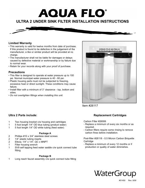
ULTRA 2 UNDER SINK FILTER INSTALLATION INSTRUCTIONSLimited Warranty• This warranty is valid for twelve months from date of purchase.If this product is found to be defective in the judgement of themanufacturer, a like or similar product will be provided at nocharge.• The manufacturer shall not be liable for damages or delayscaused by defective material or workmanship or by failure dueto normal wear.• Retain for your records along with your proof of purchase.Precautions• This <strong>filter</strong> is designed to operate at water pressure up to 100psi. Normal municipal water pressure is 40 - 60 psi.• Plastic housing parts must not be subjected to freezing,excessive heat or direct sunlight. These conditions may causefailure.• Install <strong>filter</strong> with a minimum of 3” clearance - top, bottom andsides.• Do not overtighten fittings when installing this unit.Item #26117Ultra 2 Parts include:1 Two housing bracket c/w housing and cartridges1 5 foot length 1/4” OD blue tubing (product water)1 5 foot length 1/4” OD white tubing (feed water)Package A2 Phillips #10 x 3/4” stainless steel screws2 1/4” plastic tubing inserts2 Elbow, 1/4” x 1/4”, QC x MNPT1 Filter housing wrench1 SV9 self tapping feed water saddle c/w quick connect tubefittingReplacement CartridgesCarbon Filter #26006- Replace a minimum of every six months or asrequired.- Carbon <strong>filter</strong>s require some rinsing to removecarbon fines before <strong>installation</strong>.Post-<strong>filter</strong> #26118 - 0.5 Micron Carbon BriquetteCartridge- Replace a minimum of every 12 months or ifproduction or quality of water diminishes.Package B1 Long reach faucet assembly c/w quick connect tube fitting#51450 Rev. 8/08
ULTRA 2 UNDER SINK FILTER INSTALLATION INSTRUCTIONSThis unit is not intended for use where water is microbiologically unsafe or withwater of unknown quality without adequate disinfection before or after the unit.Step 1 - Choose a LocationPosition the <strong>filter</strong> housing bracket on wallof cabinet nearest cold water linebeneath <strong>sink</strong>. Leave at least 3” clearancebetween the bottom of the <strong>filter</strong> housingand the floor. Mark bracket slots on thewall.For drilling through a metal <strong>sink</strong>, firstmake a small indentation with a punchwhere you want to install the faucet.(Caution - Wear Eye Protection WhenDrilling)For drilling through porcelain, place apiece of masking tape over the location,then score with a punch before drilling.Step 8 - Connect the Product WaterTubingFirmly push one end of the blue productwater tubing into the quick connect fittingof faucet connector as shown below. Formore details on quick connect fitting, seeinstruction #2.(1)(2)Step 2 - Install Filter CartridgesFor sanitization procedures, refer toInstructions #1. Install the Carbon <strong>filter</strong> inthe (1) sump and 0.5 Micron CarbonBriquette cartridge in the (2) sump.Step 3 - Install Screws - Package ADrill a 1/8” hole on each mark, then insertthe screws. Leave each screwapproximately 1/4” out from the wall formounting the head assembly later in the<strong>installation</strong>.Step 4 - Installing the Ultra 2 FaucetThe faucet may be installed into the holenormally used for the <strong>sink</strong> sprayer. If youhave a <strong>sink</strong> sprayer installed and plan touse it or do not have a hole, you willhave to drill a hole for the faucet. Thefaucet will fit through a 7/16” hole orlarger.Step 5 - Insert the Faucet - Package BRemove the hardware from the faucetstem for later use. Slide the large chromeplated washer onto the stem, then thelarge plastic washer. Place the faucetstem through the hole on the <strong>sink</strong>.Step 6 - Secure the FaucetSlide the small rubber washer, then thelarge metal washer and lock nut onto thefaucet stem. Tighten the lock nut tosecure the faucet in place.Step 7 - Install Faucet ConnectorApply NSF 61 grade tape over thethreads of the faucet and install thefaucet connector. Do not overtighten.Step 9 - Install Feed Water Saddle -Package ALocate a suitable area on the cold line.Following the <strong>instructions</strong> #3 supplied,attach the self tapping feed water saddleto the cold water line.Step 10 - Install Connector and theFeed Water TubingInstall the connector (PACKAGE A) to thevalve body of the saddle valve as shownin step 7 (If not using compression nutfittings). Firmly push the one end of thewhite tubing to the quick connect fitting ofthe connector as shown in Step 8.Step 11 - Install White 90 DegreeElbowsApply NSF 61 grade tape to the threadsof the white 90 degree elbow fitting andinstall them in the <strong>filter</strong> inlet and outletports.Step 12Firmly push the other end of white tubingand the other end of the blue tubing intothe quick connect fittings of elbow at theinlet and outlet side respectively. Formore details on quick connect fittings,see <strong>instructions</strong> # 2.Step 13 - Activating the SystemOpen feed water saddle and faucet.Flush unit for 2 - 3 minutes or until all theair has been expelled and the waterappears clear at the faucet.
Instruction #1 - Cleaning, Sanitizing and Cartridge Replacement Procedure1. Mix mild cleaning solution of dishsoap and clean potable water inplastic bowl.2. Relieve presure by closing feed watersupply valve and open product waterfaucet.Icemaker: Transfer ice cubes frombin/tray to clean freezer container forstorage until procedure is done.3. CAUTION: Do not attempt to remove<strong>filter</strong> housings until water flow stops.This reduces pressure insidethe system so housings may safelybe removed.CAUTION: Additional point-of-usedevices (i.e., icemakers) may use<strong>filter</strong>s along their supply line. Removeany <strong>filter</strong> or treatment device installedbetween module and device beforeproceeding.Remove each <strong>filter</strong>/membranehousing by turning it counterclockwise.Remove each <strong>filter</strong>cartridge as its housing is removed.Discard <strong>filter</strong>s.4. CAUTION: Use sanitary rubbergloves for this procedure to avoidcontaminating sanitizing solution,<strong>filter</strong>s, or membrane. Wear gloveswhenever cleaning/ sanitizing systemcomponents or handling new<strong>filter</strong>/membrane cartridges.5. Remove <strong>filter</strong> housing "O" rings andwash them with cleaning solution.Rinse them well with clean potablewater. Inspect them for damage (i.e.,nicks, scratches). Replace damaged"O" rings.6. Clean <strong>filter</strong> housings ports, inside andoutside, with washcloth and cleaningsolution. Do not use abrasivematerials.7. Rinse manifold/housings with cleanpotable water.9. Place a small amount of "O" ringlubricant over surface of <strong>filter</strong> housing"O" ring. Install "O" ring into <strong>filter</strong>housing groove.TO SANITIZE THE SYSTEM: CompleteSteps 12-20.TO INSTALL FILTERS: Complete Steps19-20.WARNING: WEAR SAFETY GLASSESWHILE PERFORMING THISPROCEDURE.READ "WARNINGS" INFORMATIONON BLEACH CONTAINER BEFOREUSING CONTENTS.HANDLE SANITIZING SOLUTIONCAREFULLY. AVOID CONTACT WITHUNPROTECTED AREAS.10. CAUTION: Excessive concentrationsof bleach will damage plastic andrubber components. Rinse all partsthat contact bleach thoroughly withclean potable water.Mix sanitizing solution of 1.5 ml (1/3teaspoon) of household bleach and3.8 L (1 gallon) of clean, potablewater in the bucket. Mix solution well.11. CAUTION: Tighten <strong>filter</strong> housings byhand only. Do not use tools as theywill over-tighten and damagehousings. Take care not to cut orpinch o-rings.Add 236 ml (one cup or 8 oz.) ofsanitizing solution to each <strong>filter</strong>housing and install them onto themanifold (do not install <strong>filter</strong>s ormembrane at this time). Tighten each<strong>filter</strong> housing by hand only.12. Slowly open source water supplyvalve.13. Open product water faucet. Closefaucet as soon as water begins toflow from spout.15. Wait 25 minutes, then open productwater faucet and let water flow todrain.16. CAUTION: Do not attempt to remove<strong>filter</strong> housings until water flow stops.This reduces pressure inside thesystem so housings may be removedsafely.Remove <strong>filter</strong> housings and disposeof water. Rinse <strong>filter</strong> housings andmanifold ports thoroughly with cleanpotable water.17. CAUTION: Do not remove protectiveplastic bag from replacement <strong>filter</strong>cartridges until so instructed.Install "O" rings into <strong>filter</strong> housings.Open top of <strong>filter</strong> bag enough toexpose <strong>filter</strong> cap and "O" ringgrooves. Place a small amount of "O"ring lubricant on surface of each "O"ring.18. CAUTION: TIGHTEN FILTERHOUSINGS BY HAND ONLY. Do notuse tools as they will over-tighten anddamage housings. Take care not tocut or pinch o-rings.CAUTION: Refer to InstallationInstructions for the location of eachcartridge.Install <strong>filter</strong> cartridges. Hold cartridgeby its protective plastic bag and insertcartridge into manifold turning it 1/4turn as it enters the port. Slide bagfrom cartridge and discard. Replaceeach <strong>filter</strong> housing as each cartridgeis installed.19. Turn feed water valve slowly to openposition.20. Confirm system is producing water.Unit will be sending rinse water todrain.8. Inspect manifold and <strong>filter</strong> housing"O" ring groove area for damage (i.e.,nicks or scratches). Replacedamaged components.14. Wait 5 minutes, then close sourcewater supply valve.