View manual - Hydrotech
View manual - Hydrotech
View manual - Hydrotech

Create successful ePaper yourself
Turn your PDF publications into a flip-book with our unique Google optimized e-Paper software.
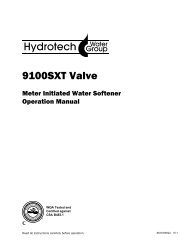
<strong>Hydrotech</strong> Taste & Odor Filter (Carbon)Performance and SpecificationsItem Model Pipe Service Peak Backwash Mineral ShippingNumber Number Media Size Flow Rate Flow Rate Flow Rate Tank size Weightcu. ft. (litres) inches (mm) USGPM (LPM) inches (mm) Lbs. (kg)7615 5600SXTM-847AC 0.75 (21) 3/4 (19) 4.0 (15) 5.0 (19) 3.5 (13) 8 x 47 (203 x 1194) 45 (20)7616 5600SXTM-948AC 1.00 (28) 3/4 (19) 4.0 (15) 6.0 (23) 4.0 (15) 9 x 48 (229 x 1219) 60 (27)7617 5600SXTM-1054AC 1.50 (42) 3/4 (19) 5.0 (19) 7.0 (27) 5.0 (19) 10 x 54 (254 x 1372) 78 (35)<strong>Hydrotech</strong> Turbidity Filter (Multi-Media)Item Model Pipe Service Peak Backwash Mineral ShippingNumber Number Media Size Flow Rate Flow Rate Flow Rate Tank size Weightcu. ft. (litres) inches (mm) USGPM (LPM) inches (mm) Lbs. (kg)7618 5600SXTM-847MM 0.75 (21) 3/4 (19) 4.0 (15) 5.0 (19) 4.0 (15) 8 x 47 (203 x 1194) 95 (43)7619 5600SXTM-948MM 1.00 (28) 3/4 (19) 5.0 (19) 7.0 (38) 5.0 (19) 9 x 48 (229 x 1219) 145 (66)7620 5600SXTM-1054MM 1.50 (42) 3/4 (19) 7.0 (38) 10.0 (38) 7.0 (38) 10 x 54 (254 x 1372) 213 (97)Caution: These water conditioners are not intended to be used for treating water that is microbiologically unsafe or of unknown quality without adequatedisinfection before or after the system.Notes:Operating Temperature Range: 34° to 110°F (1° to 43°C)Operating Pressure Range: 20 to 120psi (137 to 827 kPa)Electrical: 24V/60Hz with a supplied 120V/60Hz Wall Mount CSA Approved Transformer1. The manufacturer reserves the right to make product improvements which deviate from thespecifications and descriptions stated herein without obligation to change previously manufacturedproducts or to note the change.2. Peak flow rates are intended for intermittent use only and are for residential application only.How Your 5600 SXT Water Filter WorksRaw water enters your home through the main supply line, enters your filter, and passes downward through the mediabed. Impurities such as turbidity and sediment (multi-media filter) and organics and chlorine (taste and odor filter) areremoved from the water. The filtered water then flows into your household water lines.Periodic regeneration is required to flush entrapped material from the system.In normal operation, the Time of Day display will alternate being viewed with the Volume Remaining display. This displaywill be in gallons, liters or cubic meters. As treated water is used, the Volume Remaining display will count down from amaximum value to zero or (---). Once this occurs, a regeneration cycle will be initiated at the Set Regeneration Time. Waterflow through the valve is indicated by the Flow Indicator that will flash in direct relationship to flow rate.Example833 Gallons of TreatedWater RemainingPM IndicatorFlow Indicator(Flashing with water flow)0 Gallons of TreatedWater RemainingPM IndicatorFlow Indicator(Flashing with water flow)Control Operation During RegenerationIn regeneration, the control will display a special regeneration display. In this display, the control will show the currentregeneration step number the valve is advancing to or has reached and the time remaining in that step. The stepnumber displayed will flash until the valve has completed driving into this regeneration step position. Once allregeneration steps have been completed, the valve will return to Service and resume normal operation.ExampleLess than 6 minutesremaining in RegenStep Rapid RinsePushing the Extra Cycle Button during a regeneration cycle will immediately advance the valve to the next cycle stepposition and resume normal step timing.51
Control Operation During ProgrammingThe control will only enter the Program Mode with the valve in Service. While in the Program Mode, the control will continue tooperate normally, monitoring water usage and keeping all displays up to date. Control programming is stored in memorypermanently, eliminating the need for battery back-up power.Meter Immediate ControlA meter immediate control measures water usage and regenerates the system as soon as the calculated system capacity isdepleted. The control calculates the system capacity by dividing the unit capacity (typically expressed in grains/unit volume) bythe feedwater hardness and subtracting the reserve. Meter Immediate systems generally do not use a reserve volume.However, in twin tank systems with soft-water regeneration, the reserve capacity should be set to the volume of water usedduring regeneration to prevent hard water break-through. A Meter Immediate control will also start a regeneration cycle at theprogrammed regeneration time if a number of days equal to the regeneration day override pass before water usage depletesthe calculated system capacity.Meter Delayed ControlA Meter Delayed Control measures water usage and regenerates the system at the programmed regeneration time after thecalculated system capacity is depleted. As with Meter Immediate systems, the control calculates the system capacity bydividing the unit capacity by the feedwater hardness and subtracting the reserve. The reserve should be set to insure that thesystem delivers treated water between the time the system capacity is depleted and the actual regeneration time. A MeterDelayed control will also start a regeneration cycle at the programmed regeneration time if a number of days equal to theregeneration day override pass before water usage depletes the calculated system capacity.Time Clock Delayed ControlA Time Clock Delayed Control regenerates the system on a timed interval. The control will initiate a regeneration cycle at theprogrammed regeneration time when the number of days since the last regeneration equals the regeneration day overridevalue.Day of the Week ControlThis control regenerates the system on a weekly schedule. The schedule is defined in Master Programming by setting eachday to either “off” or “on.” The control will initiates a regeneration cycle on days that have been set to “on” at the specifiedregeneration time.Control Operation During a Power FailureThe SXT includes integral power backup. In the event of power failure, the control shifts into a power-saving mode. The controlstops monitoring water usage, and the display and motor shut down, but it continues to keep track of the time and day for aminimum of 48 hours.The system configuration settings are stored in a non-volatile memory and are stored indefinitely with or without line power.The Time of Day flashes when there has been a power failure. Press any button to stop the Time of Day from flashing.If power fails while the unit is in regeneration, the control will save the current valve position before it shuts down. When poweris restored, the control will resume the regeneration cycle from the point where power failed. Note that if power fails during aregeneration cycle, the valve will remain in it’s current position until power is restored. The valve system should include allrequired safety components to prevent overflows resulting from a power failure during regeneration.The control will not start a new regeneration cycle without line power. If the valve misses a scheduled regeneration due to apower failure, it will queue a regeneration. Once power is restored, the control will initiate a regeneration cycle the next timethat the Time of Day equals the programmed regeneration time. Typically, this means that the valve will regenerate one dayafter it was originally scheduled. If the treated water output is important and power interruptions are expected, the systemshould be setup with a sufficient reserve capacity to compensate for regeneration delays.2
Installation InstructionsAll government codes and regulations governing the installation of these devices must be observed.CAUTION: If the ground from the electrical panel or breaker box to the water meter or underground copper pipe is tiedto the copper water lines and these lines are cut during installation of the Noryl bypass valve and/or poly pipe, anapproved grounding strap must be used between the two lines that have been cut in order to maintain continuity. Thelength of the grounding strap will depend upon the number of units being installed and/or the amount of copper pipebeing replaced with poly. See Figure 1.In all cases where metal pipe was originally used and is later interrupted by poly pipe or the Noryl bypass valve as inFigure 1 or by physical separation as in Figure 2, an approved ground clamp with no less than #6 copper conductor mustbe used for continuity, to maintain proper metallic pipe bonding.Check your local electrical code for the correct clamp and cable size.Figure 1Figure 2Electrical PanelGround StrapCopper PipeOutside Water Line For Outside & 3rd Tap Comes From MeterGroundFromPanelPoly PipePoly PipeFilterc/w Plastic BypassWater MeterUnfiltered Water BypassLoop Cut & CappedFiltered Water Line in HomeGround Strap RequiredBecause of Break in Continuity1. Determine the best location for your water filter, bearing in mind the location of your water supply lines, drain lineand 120 volt AC electrical outlet. Subjecting the softener to freezing or temperatures above 110°F (43° C) will voidthe warranty.NOTE: Some units are shipped with the media bed in separate bags. To install, unscrew the control valve from thetop of the fibreglass tank, position the riser tube in the center of the tank lugging the tube with a cloth and pour themedia into the tank in the following order: coarse, fine gravel and then the filter media. Remove the cloth andcarefully screw the valve into the tank (When replacing the media, the tank must first be inverted and the old mediabed removed. See instructions provided with the replacement media).3
2. Attach the bypass valve to the control valve. Connect the inlet and outlet of the water filter to the plumbing in thehouse. The control valve must not be submitted to temperatures above 71°C (110°F). When sweatfittings are used, to avoid damaging the control valve, solder the threaded copper adapters to thecopper pipe and then, using Teflon tape, screw the assembly onto the bypass valve.CAUTION: Do not use pipe thread compound as it may attack the material in the valve body.3. Using teflon tape, screw the 1/2” hose barb into the drain port in the valve. Attach 1/2” drain hose tothe hose barb and tighten securely with a hose clamp. Run the drain line to a floor drain or alaundry drain. Complete any necessary plumbing.4. Make sure the bypass valve is in the service position.5. Plug the 24-volt transformer into a 120 VAC 60 Hz outlet. This valve has four positions: 1)Backwash 2) Brine/Rinse (not used) 3) Rapid Rinse and 4) Brine Refill (not used). When the valveis in the Service position, the extra cycle button (far left button as shown on Figure 4) must bepressed and held for 5 seconds before it activates. Press and hold the extra cycle button for 5seconds to advance the valve to the “1” Backwash position. Slowly turn on the water supply andallow the unit to backwash until the air purges out of the tank and clears the system.NOTE: On taste and odor filters, the initial water running to the drain will be very black. This iscreated by the carbon fines being flushed from the bed. Backwash all filters until the water runningto the drain is clear.6. Press the extra cycle button to advance the valve to the “2” position (not used). Press once more toadvance to the “3” position. Press once more to advance to the “4” Brine refill position. Press theextra cycle button to advance the valve back into the service position indicated by the red dot in the upper leftcorner of the display.4
Operating InstructionsFigure 3The valve has been pre-programmed with factory settings as follows:Capacity between Regenerations............1,500 gallonsRegeneration Cycle Step Programming1. Backwash ............................................6 minutes2. Brine Rinse ............................................0 minutes (not used)3. Rapid Rinse ..........................................4 minutes4. Brine Refill ............................................0 minutes (not used)Whenever the valve is in Service the current time of day can be set, the control programmed, or an extra regenerationinitiated at any time.Set Time of Day1. Press and hold either the Up or Down buttons until the programming icon replaces the service icon and theparameter display reads TD.2. Adjust the displayed time with the Up and Down buttons.3. When the desired time is set, press the Extra Cycle button to resume normal operation. The unit will also return tonormal operation after 5 seconds if no buttons are pressed.Queueing a Regeneration1. Press the Extra Cycle button. The service icon will flash to indicate that a regeneration is queued.2. To cancel a queued regeneration, press the Extra Cycle button.Regenerating ImmediatelyPress and hold the Extra Cycle button for five seconds.5
User Programming Mode OptionsAbbreviation Parameter DescriptionDO Day Override The timer’s day override settingTHIS IS AN OPTION ONLY. PLEASE DO NOT ADJUSTBEFORE CONSULTING AN AUTHORIZED DEALER.RT Regeneration Time The time of day that the system will regenerate (meter delayed,timeclock, and day-of-week systems)RC Reserve Capacity The fixed reserve capacityCD Current Day The current day of weekNOTES:Some items may not be shown depending on timer configuration.The timer will discard any changes and exit User Mode if any button is not pressed for sixty seconds.User Programming Mode Steps1. Press the Up and Down buttons for five seconds while inservice, and the time of day is NOT set to 12:01 PM.2. Use this display to adjust the Day Override. This optionsetting is identified by “DO” in the upper left hand cornerof the screen.THIS IS AN OPTION ONLY. PLEASE DO NOT ADJUSTBEFORE CONSULTING AN AUTHORIZED DEALER.3. Press the Extra Cycle button. Use this display to adjustthe Regeneration Time. This option setting is identifiedby “RT” in the upper left hand corner of the screen.4. Press the Extra Cycle button. Use this display to adjust the Fixed Reserve Capacity. This option setting is identifiedby “RC” in the upper left-hand corner of the screen.75 gallons X # of people in the house = RC # of People RC1 752 1503 2255. Press the Extra Cycle button to end User Programming Mode.6
Set treated water capacity (only available in metered systems)1. Set time of day to 12:01 PM.2. Press Extra Cycle button to exit the time of day display.3. Press and hold the Up and Down buttons together until the programming icon replaces the service icon.4. Press Extra Cycle button till “C” is displayed in the upper left corner of the screen.5. Use Up and Down buttons to set the amount of treated water that can flow through the unit before a regeneration isrequired.650 gallon capacity6. Press Extra Cycle button until it shows the “Time of Day” display.THIS IS AN OPTION ONLY. PLEASE DO NOT ADJUST BEFORE CONSULTING AN AUTHORIZED DEALER.Error CodesNote: Error codes appear on the In Service displayError Code Probable Cause Recover and Resetting[Err 0][Err 1][Err 2][Err 3]Drive motor is stalledDrive motor is running continuouslyThere have been more than 99 days sincethe last Regeneration. If the Day of theWeek mode of regeneration is selectedand days since last regeneration exceeds7 days.[ 7 - - 5 ]: There have been more than 7days since the last regeneration. Allindividual settings (d1, d2, d3, d4, d5, d6,d7) are set to 0.Control board memory failure.Unplug the unit from the power sourceWhen power is restored to the unit, the Err _ displaycode clears. If the condition causing the error hasnot been resolved the Err _ code reappears in thefour digit display. Do not attempt to troubleshoot thisproblem any further.Regeneration must occur for the unit to recover, thedisplay to clear and the valve tofunction normally.[ 7 - - 5 ]: To recover from [Err2], the user mustinitiate a regeneration or set at least one individualday to 1.Perform a Master Reset. If the error returns,do not attempt to troubleshoot this problem anyfurther.Error Display ExampleNOTE: Unit will flash when an error exists.7
Operating InstructionsWater PressureYour water filter is designed to operate under normal water pressures from 20 psi to 100 psi.Regeneration and Automatic BypassWater filters are factory set to regenerate at 11:00 p.m. during a period of little or no water use. The regeneration cyclelasts approximately 15 minutes, after which filtered water service is restored. While regeneration is taking place,"rawwater" automatically bypasses the filter if required. If possible, avoid using water during regeneration to preventunfiltered water entering your household plumbing system.(Installation Tip: The 5600SXT Filter should not be allowed to regenerate at the same time as any other watertreatment units. If adjustment is required, consult programming chart to adjust default regeneration time.)New SoundsYou will notice new sounds such as the hum of the timer, as your filter operates. During regeneration, it will not beuncommon to hear water running to the drain.Manual BypassIn case of an emergency you can isolate your water filter from the watersupply using the bypass valve located at the back of the control.In normal operation the bypass is open with the ON/OFF knobs in line withthe INLET and OUTLET pipes. To isolate the filter, simply rotate the knobsclockwise (as indicated by the word BYPASS and arrow) until they lock.You can use your water related fixtures and appliances as the water supplyis bypassing the filter. However, the water you use will be untreated.To resume filter water service, open the bypass valve by rotating the knobscounter-clockwise.OUTLETINLETManual Regeneration CycleIf you run out of filtered water because of inadequate regeneration frequency, inadequate reserve capacity, power failureor unusually high water usage, you can initiate a <strong>manual</strong> regeneration simply by pressing the extra cycle button. Thefilter will now automatically complete a regeneration cycle and return to service. If possible, avoid water use during theregeneration cycle.Once you have set your filter and you experience frequent loss of water pressure, you may have to increase thefrequency of regeneration by resetting the gallons between regeneration.Maintenance InstructionsMaintenance of your new water filter requires very little time or effort but it is essential. Regular maintenance will ensuremany years of efficient and trouble free operation.Care of all Water FiltersTo retain the attractive appearance of your new water filter, clean occasionally with a mild soap solution. DO NOT useabrasive cleaners, ammonia or solvents. Never subject your filter to freezing.Replacing Media BedTaste and Odor Filter (Carbon)Under normal operating conditions the effective life of the filter media is approximately three (3) years, after which, tasteand odor problems may return. When this occurs, contact your dealer for a replacement media bed.Turbidity Filter (Multi-Media)Under normal operating conditions the media should never need to be replaced. If you experience pressure loss andcannot correct it with a <strong>manual</strong> regeneration, your media bed may need replacing - contact your dealer.8
Trouble Shooting GuidePROBLEM CAUSE CORRECTION1. Filter bleeds taste and odor A. Bypass valve is open A. Close bypass valveor sediment B. Electrical service to unit has B. Assure permanent electrical service (checkbeen interruptedfuse, plug or switch)C. Defective or stripped media bed C. Replace mediaD. Quality of water has worsened D. Have water sample analyzed to determineany changeE. Filter capacity too small E. Replace with larger unit or add another filterF. Filter not backwashing enough F. Be sure flow control is not clogged or drainline restricted. Be sure water pressure hasnot dropped and that pump has sufficientcapacityG. Excessive water usage - G. Increase frequency of regeneration. Makecalendar clock modelssure there are no leaks in toilets or sinks2. Filter fails to regenerate A. Electrical service to unit has A. Assure permanent electrical service (checkbeen interruptedfuse, plug or switch)B. Timer is defective B. Replace timerC. Power failure C. Reset time of dayD. Timer motor does not run D. Replace defective motor3. Filter regenerates every day A. Faulty gear train A. Check the mechanical linkage on the timercontrol to eliminate possible binding in thegear train4. Loss of water pressure A. Iron or turbidity build-up in filter A. Clean control and treat bed with Iron Out.Increase frequency of regenerationB. Filter not regenerating oftenenoughB. Increase frequency of regenerationC. Not enough water volume or C. Correct water supply problempressure to backwash properly5. Loss of media through A. Air in water system A. Assure that well system has proper airdrain lineeliminator control. Check for dry wellconditionB. Backwash rate too fast B. Check drain flow control for proper flowrates6. Drain flows continuously A. Foreign material in control A. Remove piston assembly and inspect bore.Remove foreign material and check controlin various regeneration positionsB. Timer motor stopped or jammed B. Replace timer motor9
GUARANTEEHYDROTECH guarantees that your new water conditioner is built of quality material and workmanship. When properlyinstalled and maintained, it will give years of trouble-free service.FIVE YEAR COMPLETE PARTS GUARANTEEHYDROTECH will replace any part which fails within 60 months from date of manufacture, provided the failure is due to adefect in material or workmanship. The only exception shall be when proof of purchase or installation is provided and thenthe warranty period shall be from the date thereof.TEN YEAR GUARANTEE ON MINERAL TANKSHYDROTECH will provide a replacement mineral tank to any original equipment purchaser in possession of a tank that failswithin 120 months, provided that the water conditioner is at all times operated in accordance with specifications and notsubject to freezing or exposure to direct sunlight.GENERAL PROVISIONSHYDROTECH assumes no responsibility for consequential damage as a result of escaped water from the water filter; laboror expense incurred as a result of a defect or for failure to meet the terms of these guarantees because of circumstancesbeyond its control.WaterGroup Inc.Regina, SaskatchewanFridley, MinnesotaCambridge, OntarioDurham, North Carolina Calgary, Alberta1-800-354-7867 1-877-299-5999www.hydrotechwater.com