ProFloSXT Upflow Service Manual 42773 - Pentair Residential ...
ProFloSXT Upflow Service Manual 42773 - Pentair Residential ...
ProFloSXT Upflow Service Manual 42773 - Pentair Residential ...

You also want an ePaper? Increase the reach of your titles
YUMPU automatically turns print PDFs into web optimized ePapers that Google loves.
Model <strong>ProFloSXT</strong> <strong>Upflow</strong><strong>Service</strong> <strong>Manual</strong>IMPORTANT: Fill in Pertinent Information on Page 3 for Future Reference
Table of ContentsIMPORTANT PLEASE READ:• The information, specifi cations and illustrations in this manual are based on the latest information available at the time ofprinting. The manufacturer reserves the right to make changes at any time without notice.• This manual is intended as a guide for service of the valve only. System installation requires information from a number ofsuppliers not known at the time of manufacture. This product should be installed by a plumbing professional.• This unit is designed to be installed on potable water systems only.• This product must be installed in compliance with all state and municipal plumbing and electrical codes. Permits may berequired at the time of installation.• If daytime operating pressure exceeds 80 psi, nighttime pressures may exceed pressure limits. A pressure reducing valve mustbe installed.• Do not install the unit where temperatures may drop below 32°F (0°C) or above 110°F (43°C).• Do not place the unit in direct sunlight. Black units will absorb radiant heat increasing internal temperatures.• Do not strike the valve or any of the components.• Warranty of this product extends to manufacturing defects. Misapplication of this product may result in failure to properlycondition water, or damage to product.• A prefilter should be used on installations in which free solids are present.• In some applications local municipalities treat water with Chloramines. High Chloramine levels may damage valve components.• Correct and constant voltage must be supplied to the control valve to maintain proper function.
Job Specification SheetJob Number: __________________Model Number: ________________Water Hardness: ___________________ ppm or gpgCapacity Per Unit: ______________Mineral Tank Size: ___________ Diameter: ___________ Height:Salt Setting per Regeneration: _____________________________________________1. Type of Timer:A. 7 Day or 12 Day B. Meter Initiated2. Downflow <strong>Upflow</strong> <strong>Upflow</strong> Variable3. Meter Size:A. 3/4” Std Range (125 - 2,100 gallon setting)B. 3/4” Ext Range (625 - 10,625 gallon setting)C. 1” Std Range (310 - 5,270 gallon setting)D. 1” Ext Range (1,150 - 26,350 gallon setting)E. 1 1/2” Std Range (625 - 10,625 gallon setting)F. 1 1/2” Ext Range (3,125 - 53,125 gallon setting)G. 2” Std Range (1,250 - 21,250 gallon setting)H. 2” Ext Range (6,250 - 106,250 gallon setting)I. 3” Std Range (3,750 - 63,750 gallon setting)J. 3” Ext Range (18,750 - 318,750 gallon setting)K. Electronic __________ Pulse Count __________ Meter Size4. System Type:A. System #4: 1 Tank, 1 Meter, Immediate, or Delayed RegenerationB. System #4: Time ClockC. System #4: Twin TankD. System #5: 2-5 Tanks, 2 Meters, InterlockE. System #6: 2-5 Tanks, 1 Meter, Series RegenerationF. System #7: 2-5 Tanks, 1 Meter, AlternatingG. System #9: Electronic Only, 2-4 Tanks, Meter per Valve, AlternatingH. System #14: Electronic Only, 2-4 Tanks, Meter per Valve. Brings units on and offl ine based on flow.5. Timer Program Settings:A. Backwash: ____________________ MinutesB. Brine and Slow Rinse: ___________ MinutesC. Rapid Rinse: __________________ MinutesD. Brine Tank Refill: _______________ MinutesE. Pause Time: __________________ MinutesF. Second Backwash: _____________ Minutes6. Drain Line Flow Control: ____________ gpm7. Brine Line Flow Controller: __________________ gpm8. Injector Size#: _____________________9. Piston Type:A. Hard Water BypassB. No Hard Water BypassPage D
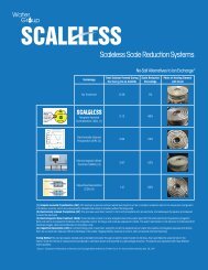
Installation InstructionsWATER PRESSURE: A minimum of 20 pounds of water pressure is required for regeneration valve to operate effectively.ELECTRICAL FACILITIES: An uninterrupted alternating current (A/C) supply is required. Note: Other voltages are available.Please make sure your voltage supply is compatible with your unit before installation.EXISTING PLUMBING: Condition of existing plumbing should be free from lime and iron buildup. Piping that is built up heavilywith lime and/or iron should be replaced. If piping is clogged with iron, a separate iron filter unit should be installed ahead ofthe water softener.LOCATION OF SOFTENER AND DRAIN: The softener should be located close to a drain to prevent air breaks and back fl ow.BY-PASS VALVES: Always provide for the installation of a by-pass valve if unit is not equipped with one.CAUTION: Water pressure is not to exceed 125 psi, water temperature is not to exceed 110°F, and the unit cannot besubjected to freezing conditions.Installation Instructions1.2.3.4.5.6.7.8.9.Place the softener tank where you want to install the unit making sure the unit is level and on a firm base.During cold weather, the installer should warm the valve to room temperature before operating.All plumbing should be done in accordance with local plumbing codes. The pipe size for residential drain line should bea minimum of 1/2”. Backwash flow rates in excess of 7 gpm or length in excess of 20’ require 3/4” drain line. Commercialdrain lines should be the same size as the drain line flow control.Refer to the dimensional drawing for cutting height of the distributor tube. If there is no dimensional drawing, cut thedistributor tube flush with the top of the tank.Lubricate the distributor o-ring seal and tank “o” ring seal. Place the main control valve on tank.Note: Only use silicone lubricant.Solder joints near the drain must be done prior to connecting the Drain Line Flow Control fitting(DLFC). Leave at least 6” between the DLFC and solder joints when soldering pipes that areconnected on the DLFC. Failure to do this could cause interior damage to the DLFC.Teflon tape is the only sealant to be used on the drain fitting. The drain from twin tank units maybe run through a common line.Make sure that the floor is clean beneath the salt storage tank and that it is level.Place approximately 1” of water above the grid plate. If a grid is not utilized, fill to the top of theair check in the salt tank. Do not add salt to the brine tank at this time.10. On units with a by-pass, place in by-pass position. Turn on the main water supply. Open a coldsoft water tap nearby and let run a few minutes or until the system is free from foreign material(usually solder) that may have resulted from the installation. Once clean, close the water tap.11. Slowly place the by-pass in service position and let water flow into the mineral tank. When waterflow stops, slowly open a cold water tap nearby and let run until the air is purged from the unit.12. Plug unit into an electrical outlet. Note: All electrical connections must be connected according tolocal codes. (Be certain the outlet is uninterrupted).NOTE: <strong>Residential</strong>Air Check ValvePictured AbovePage 4
Start-Up InstructionsThe water softener should be installed with the inlet, outlet, and drain connections made in accordance with themanufacturer’s recommendations, and to meet applicable plumbing codes.1.2.3.4.5.6.7.Turn the manual regeneraton knob slowly in a clockwise direction until the program micro switch lifts on top ofthe fi rst set of pins. Allow the drive motor to move the piston to the fi rst regeneration step and stop. Each timethe program switch position changes, the valve will advance to the next regeneration step. Always allow themotor to stop before moving to the next set of pins or spaces.NOTE: For electronic valves, please refer to the manual regeneration part of the timer operationsection. If the valve came with a separate electronic timer service manual, refer to the timer operationsection of the electronic timer service manual.Position the valve to backwash. Ensure the drain line fl ow remains steady for 10 minutes or until the waterruns clear (see above).Position the valve to the brine / slow rinse position. Ensure the unit is drawing water from the brine tank (thisstep may need to be repeated).Position the valve to the rapid rinse position. Check the drain line flow, and run for 5 minutes or until the waterruns clear.Position the valve to the start of the brine tank fill cycle. Ensure water goes into the brine tank at the desiredrate. The brine valve drive cam will hold the valve in this position to fi ll the brine tank for the first regeneration.Replace control box cover.Put salt in the brine tank.NOTE: Do not use granulated or rock salt.Page 5
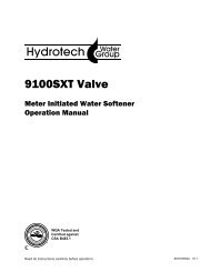
Timer FeaturesError/InformationIconParameterDisplayDataDisplayPMIndicator<strong>Service</strong>IconFlow Indicatorx1000 IndicatorProgrammingIconExtra CycleButtonUpButtonDownButtonFeatures of the SXT:• Power backup that continues to keep time and the passage of days for a minimum of 48 hours in the event ofpower failure. During a power outage, the control goes into a power-saving mode. It does not monitor waterusage during a power failure, but it does store the volume remaining at the time of power failure.• Settings for both valve (basic system) and control type (method used to trigger a regeneration).• Day-of-the-Week controls.• While in service, the display alternates between time of day, volume remaining or days to regeneration, andtank in service (twin tank systems only).• The Flow Indicator fl ashes when outlet flow is detected.• The <strong>Service</strong> Icon fl ashes if a regeneration cycle has been queued.• A Regeneration can be triggered immediately by pressing the Extra Cycle button for five seconds.• The Parameter Display displays the current Cycle Step (BW, BF, RR, etc) during regeneration, and the datadisplay counts down the time remaining for that cycle step. While the valve is transferring to a new cycle step,the display will fl ash. The parameter display will identify the destination cycle step (BW, BF, RR, etc) and thedata display will read “----”. Once the valve reaches the cycle step, the display will stop fl ashing and the datadisplay will change to the time remaining. During regeneration, the user can force the control to advance tothe next cycle step immediately by pressing the extra cycle button.Page 6
Setting the Time of Day1.2.3.Timer FeaturesPress and hold either the Up or Down buttons until the programming icon replaces the service icon and theparameter display reads TD.Adjust the displayed time with the Up and Down buttons.When the desired time is set, press the Extra Cycle button to resume normal operation. The unit will alsoreturn to normal operation after 5 seconds if no buttons are pressed.Queueing a Regeneration1.2.Press the Extra Cycle button. The service icon will flash to indicate that a regeneration is queued.To cancel a queued regeneration, press the Extra Cycle button.Regenerating ImmediatelyPress and hold the Extra Cycle button for fi ve seconds.Page 7
Timer OperationMeter Immediate ControlA meter immediate control measures water usage and regenerates the system as soon as the calculated systemcapacity is depleted. The control calculates the system capacity by dividing the unit capacity (typically expressedin grains/unit volume) by the feedwater hardness and subtracting the reserve. Meter Immediate systems generallydo not use a reserve volume. However, in twin tank systems with soft-water regeneration, the reserve capacityshould be set to the volume of water used during regeneration to prevent hard water break-through. A MeterImmediate control will also start a regeneration cycle at the programmed regeneration time if a number of daysequal to the regeneration day override pass before water usage depletes the calculated system capacity.Meter Delayed ControlA Meter Delayed Control measures water usage and regenerates the system at the programmed regenerationtime after the calculated system capacity is depleted. As with Meter Immediate systems, the control calculates thesystem capacity by dividing the unit capacity by the feedwater hardness and subtracting the reserve. The reserveshould be set to insure that the system delivers treated water between the time the system capacity is depletedand the actual regeneration time. A Meter Delayed control will also start a regeneration cycle at the programmedregeneration time if a number of days equal to the regeneration day override pass before water usage depletesthe calculated system capacity.Time Clock Delayed ControlA Time Clock Delayed Control regenerates the system on a timed interval. The control will initiate a regenerationcycle at the programmed regeneration time when the number of days since the last regeneration equals theregeneration day override value.Day of the Week ControlThis control regenerates the system on a weekly schedule. The schedule is defi ned in Master Programming bysetting each day to either “off” or “on.” The control will initiates a regeneration cycle on days that have been set to“on” at the specifi ed regeneration time.Control Operation During RegenerationDuring regeneration, the control displays a special regeneration display. In this display, the control shows thecurrent regeneration step number the valve is advancing to, or has reached, and the time remaining in that step.The step number that displays fl ashes until the valve completes driving to this regeneration step position. Once allregeneration steps are complete the valve returns to service and resumes normal operation.Pressing the Extra Cycle button during a regeneration cycle immediately advances the valve to the next cyclestep position and resumes normal step timing.Control Operation During ProgrammingThe control only enters the Program Mode with the valve in service. While in the Program Mode, the controlcontinues to operate normally monitoring water usage and keeping all displays up to date. Control programming isstored in memory permanently, eliminating the need for battery backup power.<strong>Manual</strong>ly Initiating a Regeneration1. When timer is in service, press the Extra Cycle button for 5 seconds on the main screen.2. The timer advances to Regeneration Cycle Step #1 (backwash), and begins programmed time count down.3. Press the Extra Cycle button once to advance valve to Regeneration Cycle Step #2 (brine draw & slow rinse).4. Press the Extra Cycle button once to advance valve to Regeneration Cycle Step #3 (rapid rinse).5. Press the Extra Cycle button once to advance valve to Regeneration Cycle Step #4 (brine refi ll).6. Press the Extra Cycle button once more to advance the valve back to in service.NOTE: If the unit is a fi lter or upfl ow, the cycle step order may change.NOTE: A queued regeneration can be initiated by pressing the Extra Cycle button. To clear a queued regeneration,press the Extra Cycle button again to cancel. If regeneration occurs for any reason prior to the delayedregeneration time, the manual regeneration request shall be cleared.Page 8
Control Operation During A Power FailureTimer OperationThe SXT includes integral power backup. In the event of power failure, the control shifts into a power-savingmode. The control stops monitoring water usage, and the display and motor shut down, but it continues to keeptrack of the time and day for a minimum of 48 hours.The system confi guration settings are stored in a non-volatile memory and are stored indefinitely with or withoutline power. The Time of Day fl ashes when there has been a power failure. Press any button to stop the Time ofDay from fl ashing.If power fails while the unit is in regeneration, the control will save the current valve position before it shuts down.When power is restored, the control will resume the regeneration cycle from the point where power failed. Notethat if power fails during a regeneration cycle, the valve will remain in it’s current position until power is restored.The valve system should include all required safety components to prevent overfl ows resulting from a powerfailure during regeneration.The control will not start a new regeneration cycle without line power. If the valve misses a scheduledregeneration due to a power failure, it will queue a regeneration. Once power is restored, the control will initiatea regeneration cycle the next time that the Time of Day equals the programmed regeneration time. Typically,this means that the valve will regenerate one day after it was originally scheduled. If the treated water output isimportant and power interruptions are expected, the system should be setup with a sufficient reserve capacity tocompensate for regeneration delays.Page 9
Master Programming Mode ChartAbbreviation Parameter OptionAbbreviationDFVTCTNTDisplay FormatValve TypeControl TypeNumber of TanksMaster Programming OptionsGALLtrCuSt1bSt2bFltrUFbFOthrFdFItcdAYGallonsLitersCubic MetersOptionsStandard Downfl ow/<strong>Upflow</strong> Single BackwashStandard Downfl ow/<strong>Upflow</strong> Double BackwashFilterUpfl ow Brine FirstOtherMeter (Flow) DelayedMeter (Flow) ImmediateTime ClockDay of Week1 Single Tank System2 Two Tank SystemU1Tank 1 in <strong>Service</strong>TSTank in <strong>Service</strong>U2Tank 2 in <strong>Service</strong>C Unit Capacity Unit Capacity (Grains)HFeedwaterHardnessHardness of Inlet WaterRS Reserve Selection SF Percentage Safety FactorSFRCSafety FactorFixed ReserveCapacityrcFixed Reserve CapacityPercentage of the system capacity to be used as areserveFixed volume to be used as a reserveDO Day Override The system’s day override settingRT Regen Time The time of day the system will regenerateBW, BD, RR,BFD1, D2, D3, D4,D5, D6, & D7Regen Cycle StepTimesDay of WeekSettingsThe time duration for each regeneration step. Adjustablefrom OFF and 0-199 minutes.NOTE: If “Othr” is chosen under “Valve Type”, thenR1, R2, R3, etc, will be displayed insteadRegeneration setting (On or OFF) for each day of theweek on day-of-week systemsCD Current Day The Current day of the weekCAUTION: Before entering Master Programming, please contact your local professional water dealer.Page 10
Master Programming Mode ChartFMFlow Meter TypeMaster Programming Optionst0.7 3/4” Turbine MeterP0.7 3/4” Paddle Wheel Metert1.0 1” Turbine MeterP1.0 1” Paddle Wheel Metert1.5 1.5” Turbine MeterP1.5 1.5” Paddle Wheel MeterGenGeneric or Other MeterK Meter Pulse Setting Meter pulses per gallon for generic/other flow meterNOTES:Some items may not be shown depending on timer configuration.The timer will discard any changes and exit Master Programming Mode if any button is not pressed forsixty seconds.CAUTION: Before entering Master Programming, please contact your local professional water dealer.Page 11
Master Programming ModeWhen the Master Programming Mode is entered, all available option setting displays may be viewed and set asneeded. Depending on current option settings, some parameters cannot be viewed or set.Entering Master Programming ModeSet the Time Of Day display to 12:01 P.M. Then press and hold the Up and Down buttons together until theprogramming icon replaces the service icon and the Display Format screen appears.Exiting Master Programming ModePress the Extra Cycle button to accept the displayed settings and cycle to the next parameter. Press theExtra Cycle button at the last parameter to save all settings and return to normal operation. The controlwill automatically disregard any programming changes and return to normal operation if it is left in MasterProgramming mode for 5 minutes without any keypad input.Resets:Soft Reset: Press and hold the Extra Cycle and Down buttons for 25 seconds while in normal <strong>Service</strong> mode.This resets all parameters to the system default values, except the volume remaining in meter immediate or meterdelayed systems and days since regeneration in the time clock system.Master Reset: Hold the Extra Cycle button while powering up the unit. This resets all of the parameters in theunit. Check and verify the choices selected in Master Programming Mode.1. Display Format (Display Code DF)This is the fi rst screen that appears when entering Master Programming Mode. The Display Format settingspecifi es the unit of measure that will be used for volume and how the control will display the Time of Day. Thisoption setting is identifi ed by “DF” in the upper left hand corner of the screen. There are three possible settings:Display Format Setting Unit of Volume Time DisplayGAL U.S. Gallons 12-Hour AM/PMLtr Liters 24-HourCu Cubic Meters 24-HourCAUTION: Before entering Master Programming, please contact your local professional water dealer.Page 12
Master Programming Mode2. Valve Type (Display Code VT)Press the Extra Cycle button. Use this display to set the Valve Type. The Valve Type setting specifies the type ofcycle that the valve follows during regeneration. Note that some valve types require that the valve be built withspecifi c subcomponents. Ensure the valve is configured properly before changing the Valve Type setting. Thisoption setting is identifi ed by “VT” in the upper left hand corner of the screen. There are 5 possible settings:AbbreviationSt1bSt2bFltrUFbFOthrParameterStandard Downfl ow/<strong>Upflow</strong>, Single BackwashStandard Downfl ow/<strong>Upflow</strong>, Double BackwashFilterUpfl ow Brine FirstOther3. Control Type (Display Code CT)Press the Extra Cycle button. Use this display to set the Control Type. This specifi es how the control determineswhen to trigger a regeneration. For details on how the various options function, refer to the “Timer Operation”section of this service manual. This option setting is identified by “CT” in the upper left hand corner of the screen.There are four possible settings:Meter Delayed:Meter Immediate:Time Clock:Day of Week:FdFItcdAY4. Number of Tanks (Display Code NT)Press the Extra Cycle button. Use this display to set the Number of Tanks in your system. This option setting isidentifi ed by “NT” in the upper left hand corner of the screen. There are two possible settings:Single Tank System: 1Two-Tank System: 2CAUTION: Before entering Master Programming, please contact your local professional water dealer.Page 13
Master Programming Mode5. Tank in <strong>Service</strong> (Display Code TS)Press the Extra Cycle button. Use this display to set whether tank one or tank two is in service. This option settingis identifi ed by “TS” in the upper left hand corner of the screen. This parameter is only available if the number oftanks has been set to 2. There are two possible settings:Tank One in <strong>Service</strong>:Tank Two in <strong>Service</strong>:U1U26. Unit Capacity (Display Code C)Press the Extra Cycle button. Use this display to set the Unit Capacity. This setting specifies the treatmentcapacity of the system media. Enter the capacity of the media bed in grains of hardness when confi guring asoftener system, and in the desired volume capacity when configuring a filter system. This option setting isidentifi ed by “C” in the upper left hand corner of the screen. The Unit Capacity parameter is only available if thecontrol type has been set to one of the metered options. Use the Up and Down buttons to adjust the value asneeded.Range: 1-999,9900 grain capacity7. Feedwater Hardness (Display Code H)Press the Extra Cycle button. Use this display to set the Feedwater Hardness. Enter the feedwater hardness ingrains per unit volume for softener systems, or 1 for fi lter systems. This option setting is identifi ed by “H” in theupper left hand corner of the screen. The feedwater hardness parameter is only available if the control type hasbeen set to one of the metered options. Use the Up and Down buttons to adjust the value as needed.Range: 4-199 hardnessCAUTION: Before entering Master Programming, please contact your local professional water dealer.Page 14
Master Programming Mode8. Reserve Selection (Display Code RS)Press the Extra Cycle button. Use this display to set the Safety Factor. Use this display to select the type ofreserve to be used in your system. This setting is identified by “RS” in the upper left-hand corner of the screen.The reserve selection parameter is only available if the control type has been set to one of the metered options.There are two possible settings.FSrcSafety FectorFixed Reserve Capacity9. Safety Factor (Display Code SF)Press the Extra Cycle button. Use this display to set the Safety Factor. This setting specifies what percentage ofthe system capacity will be held as a reserve. Since this value is expressed as a percentage, any change to theunit capacity or feedwater hardness that changes the calculated system capacity will result in a correspondingchange to the reserve volume.This option setting is identifi ed by “SF” in the upper left hand corner of the screen.Use the Up and Down buttons to adjust the value from 0 to 50% as needed.Range: 0-50%10. Fixed Reserve Capacity (Display Code RC)Press the Extra Cycle button. Use this display to set the Reserve Capacity. This setting specifi es a fixedvolume that will be held as a reserve. The reserve capacity cannot be set to a value greater than one-half of thecalculated system capacity. The reserve capacity is a fixed volume and does not change if the unit capacity orfeedwater hardness are changed. This option setting is identifi ed by “RC” in the upper left-hand corner of thescreen. Use the Up and Down buttons to adjust the value as needed.Range: 0-half the calculated capacityCAUTION: Before entering Master Programming, please contact your local professional water dealer.Page 15
Master Programming Mode11. Day Override (Display Code DO)Press the Extra Cycle button. Use this display to set the Day Override. This setting specifi es the maximumnumber of days between regeneration cycles. If the system is set to a timer-type control, the day override settingdetermines how often the system will regenerate. A metered system will regenerate regardless of usage if thedays since last regeneration cycle equal the day override setting. Setting the day override value to “OFF” disablesthis function. This option setting is identifi ed by “DO” in the upper left hand corner of the screen. Use the Up andDown buttons to adjust the value as needed.Range: Off-99 days12. Regeneration TimePress the Extra Cycle button. Use this display to set the Regeneration Time. This setting specifi es the time of daythe control will initiate a delayed, manually queued, or day override triggered regeneration. This option setting isidentifi ed by “RT” in the upper left hand corner of the screen. Use the Up and Down buttons to adjust the value asneeded.13. Regeneration Cycle Step TimesPress the Extra Cycle button. Use this display to set the Regeneration Cycle Step Times. The differentregeneration cycles are listed in sequence based on the valve type selected for the system, and are identifiedby an abbreviation in the upper left-hand corner of the screen. The abbreviations used are listed below. If thesystem has been confi gured with the “OTHER” valve type, the regeneration cycles will be identified as R1, R2,R3, R4, R5, and R6. Each cycle step time can be set from 0 to 199 minutes, or “OFF.” Setting a cycle step to“OFF” will disable all of the following steps. Setting a cycle step time to 0 will cause the control to skip that stepduring regeneration, but keeps the following steps available. Use the Up and Down buttons to adjust the value asneeded. Press the Extra Cycle button to accept the current setting and move to the next parameter.Cycle StepBDBFBWRRSVAbbreviationBrine DrawBrine FillBackwashRapid Rinse<strong>Service</strong>Range: 0-199 minutesCAUTION: Before entering Master Programming, please contact your local professional water dealer.Page 16
Master Programming Mode14. Day of Week SettingsPress the Extra Cycle button. Use this display to set the regeneration schedule for a system confi gured as a Dayof Week control. The different days of the week are identified as D1, D2, D3, D4, D5, D6, and D7 in the upperleft-hand corner of the display. Set the value to “ON” to schedule a regeneration or “OFF” to skip regeneration foreach day. Use the Up and Down buttons to adjust the setting as needed. Press the Extra Cycle button to acceptthe setting and move to the next day. Note that the control requires at least one day to be set to “ON.” If all 7 daysare set to “OFF”, the unit will return to Day One until one or more days are set to “ON.”15. Current Day (Display Code CD)Press the Extra Cycle button. Use this display to set the current day on systems that have been confi gured asDay of Week controls. This setting is identifi ed by “CD” in the upper left-hand corner of the screen. Use the Upand Down buttons to select from Day 1 through Day 7.16. Flow Meter Type (Display Code FM)Press the Extra Cycle button. Use this display to set the type of fl ow meter connected to the control. This optionsetting is identifi ed by “FM” in the upper left-hand corner of the screen. Use the Up and Down buttons to selectone of the 7 available settings.t0.7 Fleck 3/4” Turbine MeterP0.7 Fleck 3/4” Paddle Wheel Metert1.0 Fleck 1” Turbine MeterP1.0 Fleck 1” Paddle Wheel Metert1.5 Fleck 1 1/2” Turbine MeterP1.5 Fleck 1 1/2” Paddle Wheel MeterGEn Generic/Other MeterCAUTION: Before entering Master Programming, please contact your local professional water dealer.Page 17
Master Programming Mode17. Meter Pulse Setting (Display Code K)Press the Extra Cycle button. Use this display to specify the meter pulse setting for a non-standard fl ow meter.This option setting is identifi ed by “K” in the upper left-hand corner of the screen. Use the Up and Down buttons toenter the meter constant in pulses per unit volume.18. Press the Extra Cycle button to save all settings and exit Master Programming Mode.Page 18
User Programming ModeUser Programming Mode OptionsAbbreviation Parameter DescriptionDO Day Override The timer’s day override settingRT Regeneration Time The time of day that the systemwill regenerate (meter delayed,timeclock, and day-of-weeksystems)H Feed Water Hardness The hardness of the inlet water- used to calculate system capacityfor metered systemsRC Reserve Capacity The fixed reserve capacityCD Current Day The current day of weekNOTES:Some items may not be shown depending on timer configuration.The timer will discard any changes and exit User Mode if any button is not pressed for sixty seconds.User Programming Mode Steps1.2.Press the Up and Down buttons for fi ve seconds while in service, and the time of day is NOT set to 12:01 PM.Use this display to adjust the Day Override. This option setting is identified by “DO” in the upper left handcorner of the screen.3.Press the Extra Cycle button. Use this display to adjust the Regeneration Time. This option setting is identifi edby “RT” in the upper left hand corner of the screen.4.Press the Extra Cycle button. Use this display to adjust the Feed Water Hardness. This option setting isidentifi ed by “FH” in the upper left hand corner of the screen.Range: 4-199 hardnessPage 19
User Programming Mode1.Press the Extra Cycle button. Use this display to adjust the Fixed Reserve Capacity. This option setting isidentifi ed by “RC” in the upper left-hand corner of the screen.2.Press the Extra Cycle button. Use this display to set the Current Day of the Week. This option setting isidentifi ed by “CD” in the upper left hand corner of the screen.3.Press the Extra Cycle button to end User Programming Mode.Page 20
Diagnostic Programming Mode1.Press the Up button. Use this display to view the Reserve Capacity. This option setting is identifi ed by “RC” inthe upper left hand corner of the screen.2.Press the Up button. Use this display to view the Software Version. This option setting is identified by “SV” inthe upper left hand corner of the screen.3.Press the Extra Cycle button to end Diagnostic Programming Mode.Page 22
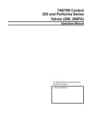
Powerhead Assembly1209101112161716151314316216181191645678Item No. Quantity Part No. Description1 .......................1 ........................ 40269 ............................PLATE, FRONT2 .......................2 ........................ 10218 ............................SWITCH, MICRO3 .......................2 ........................ 17876 ............................SCREW, PHIL PAN, 4-40 X 1-1/8”4 .......................1 ........................ 40326 ............................LABEL, COVER-UP, PROFLOSE5 .......................1 ........................ 42196 ............................CIRCUIT BOARD, SXT CONTROL6 .......................1 ........................ 42635-01 .......................FRONT COVER, SXT, SQUARE, BLACK7 .......................1 ........................ 42637 ............................LABEL, DISPLAY, SXT8 .......................1 ........................ 18260 ............................COVER, FRONT9 .......................1 ........................ 19928 ............................CAM, SWITCH, UPFLOW10 .....................1 ........................ 18211-01 .......................GEAR MAIN, DOWNFLOW, MACHD11 .....................1 ........................ 18252 ............................CAM, BRINE VALVE, UPFLOW12 .....................1 ........................ 18202 ............................BACK PLATE13 .....................1 ........................ 40251 ............................MOTOR, 24V - 50/60HZ14 .....................2 ........................ 13602 ............................SCREW, PHIL RD HD, 6-32 X 5/1615 .....................1 ........................ 18655 ............................PIN, ROLL, 3/32 X 1/216 .....................6 ........................ 13296 ............................SCREW, HEXWASHER, 6-20 X 1/217 .....................1 ........................ 13363 ............................WASHER, PLAIN, .145 ID SS18 .....................1 ........................ 13547 ............................STRAIN RELIEF, ROUND CORD19 .....................1 ........................ 18259-02 .......................COVER, BACK, BLACK20 .....................2 ........................ 18261 ............................SCREW, HEXWASHER HEAD, #10-24 X .81For <strong>Service</strong> Assembly Numbers, See the Back of this <strong>Manual</strong>Page 23
Control Valve AssemblyPage 24
Control Valve AssemblyItem No. Quantity Part No. Description1 .......................1 ........................ 18815-20 .......................VALVE BODY ASSY,5000,W/MIXING2 .......................1 ........................ 18264 ............................Spacer, End, 50003 .......................4 ........................ 14241 ............................Spacer, 56004 .......................5 ........................ 13242 ............................Seal, 56005 .......................1 ........................ 18266 ............................PISTON,5000,UPFLOW6 .......................1 ........................ 14309 ............................Retainer, Piston Rod7 .......................1 ........................ 18268 ............................End Plug Assy8 .......................3 ........................ 18261 ............................Screw, Hex Wsh Hd, 10-24 x 13/169 .......................1 ........................ 18267 ............................Rod, Piston10 .....................1 ........................ 17978 ............................Brine Valve Stem, 5600, Plastic11 .....................1 ........................ 18755 ............................O-ring, Brine Seat12 .....................1 ........................ 13167 ............................Spacer, Brine Valve13 .....................1 ........................ 12550 ............................Quad Ring, -00914 .....................2 ........................ 13302 ............................O Ring, -01415 .....................1 ........................ 13165 ............................Cap, Brine Valve16 .....................1 ........................ 11973 ............................Spring, Brine Valve17 .....................1 ........................ 16098 ............................Washer, Nylon, Brine18 .....................1 ........................ 11981-01 .......................Ring, Retaining19 .....................1 ........................ 11183.............................O-Ring, -01720 .....................1 ...............................................................Flow Washer (specify size)21 .....................1 ........................ 11385-01 .......................Housing, Flow Control, Plastic22 .....................1 ........................ 18312 ............................Retainer, Drain23 .....................1 ........................ 13304 ............................O-Ring, -12124 .....................1 ........................ 18303 ............................O-Ring, -33625 .....................2 ........................ 10141 ............................O-Ring, -01026 .....................1 ........................ 18276 ............................Plug, Injector27 .....................2 ........................ 13771 ............................O-Ring, -01228 .....................1 ........................ 18275-X ........................Throat, Injector (specify size) 000, 00, 0, 1, 2, 329 .....................1 ........................ 18274-X ........................Nozzle, Injector (specify size) 000, 00, 0, 1, 2, 330 .....................1 ........................ 18273 ............................Vortex, Generator31 .....................1 ........................ 18271 ............................Screen, Injector, 500032 .....................1 ........................ 40064 ............................Seal, Injector, 420033 .....................1 ........................ 18278-20 .......................INJECTOR CAP ASSY,1610, REGULATED,5000,20 PSI,BLACK.........................1 ........................ 18278-30 .......................INJECTOR CAP ASSY,1610, REGULATED,5000 30 PSI,GRAY34 .....................2 ........................ 18262 ............................Screw, Hex Wsh Hd, 10-24 x 135 .....................1 ........................ 12977 ............................O-Ring, -01536 .....................1 ........................ 13245 ............................Retainer, BLFC37 .....................1 ...............................................................Flow Washer (specify size)38 .....................1 ........................ 13244 ............................Adapter, BLFC39 .....................1 ........................ 13308 ............................Fitting, Hose Barb, Black.........................1 ........................ 12338 ............................Fitting, Elbow, 90 Deg, 1/2 Black40 .....................1 ........................ 18280 ............................Collector, Top, 1” x .011 Gray Bayonet.........................1 ........................ 18280-01 .......................Collector, Top, 1” x .020, White Wide Slot, Bayonet.........................1 ........................ 18280-02 .......................Collector, Top, 1” x .008, Red Narow Slot, Bayonet41 .....................1 ........................ 14613 ............................Flow StraightenerFilter Only (Not Shown).........................1 ........................ 13857 ............................Injector Plug Assy, w/O-ring.........................1 ........................ 13918 ............................Plug, BLFC Module.........................1 ........................ 18276-01 .......................INJECTOR ASSY,PLUG,W/O-RINGSOPTION - Adapter Coupling Day Clock Only45 .....................2 ........................ 19228 ............................Coupling, Adapter46 .....................4 ........................ 13305 ............................O-Ring, -11947 .....................2 ........................ 13255 ............................Clip, Mounting48 .....................2 ........................ 13314 ............................Screw, Slot Ind Hex, 18-8 x .60For <strong>Service</strong> Assembly Numbers, See the Back of this <strong>Manual</strong>Page 25
3/4” Turbine Meter AssemblyItem No. Quantity Part No. Description1 ................... 2 .................... 13314 ......................Screw, Hex Washer, 8-18 x 5/82 ................... 2 .................... 19569 ......................Clip, Flow Meter3 ................... 1 .................... 19797 ......................Meter Body Assembly, 3/4” Turbine4 ................... 4 .................... 13305 ......................O-ring, 1195 ................... 1 .................... 19791-01 .................Harness Assembly, Flow Meter..................... 1 .................... 19791-02 .................Meter Cable Assy, 35”Not Shown:..................... 1 .................... 14613 ......................Flow StraightenerPage 26For <strong>Service</strong> Assembly Numbers, See the Back of this <strong>Manual</strong>
Bypass Valve Assembly (Plastic)Item No. Quantity Part No. Description1 ..................2 ...................13305 ......................O-ring, -1192 ..................2 ...................13255 ......................Clip, Mounting3 ..................2 ...................13314 ......................Screw, Slot Ind Hex, 8-18 x .604A ...............1 ...................18706 ......................Yoke, 1”, NPT, Plastic..........................................18706-02 .................Yoke, 3/4”, NPT, Plastic4B ...............1 ...................13708-40 .................Yoke, 1”, Sweat..........................................13708-45 .................Yoke, 3/4”, Sweat..........................................19275 ......................Yoke, Angle 90 Deg, 3/4”, NPT..........................................19275-45 .................Yoke, Angle 90 Deg, 3/4” Sweat..........................................19620-01 .................Yoke Assy, 3/4”, R/Angle, 90 Deg w/O-rings, Clips & screws..........................................40636 ......................Yoke, 1 1/4”, NPT..........................................40636-49 .................Yoke, 1 1/4”, Sweat..........................................41027-01 .................Yoke, 3/4”, NPT, Cast, Machd..........................................41026-01 .................Yoke, 1”, NPT, Cast, Machd, SSFor <strong>Service</strong> Assembly Numbers, See the Back of this <strong>Manual</strong>Page 27
Bypass Valve Assembly (Metal)Item No. Quantity Part No. Description1 ................... 1 .................... 40614 ......................By-Pass Body, 3/4”............................................ 40634 ......................By-Pass Body, 1”, SS2 ................... 1 .................... 14105 ......................Seal, By-Pass, 560CD3 ................... 1 .................... 11972 ......................Plug, Bypass, w/Wax4 ................... 1 .................... 11978 ......................Plate, Bypass, Top5 ................... 1 .................... 13604-01 .................Label, Bypass, Standard Mount6 ................... 8 .................... 15727 ......................Screw, Hex Wsh Hd, 10-24 x 1/27 ................... 1 .................... 11986 ......................Plate, Bypass, Bottom8 ................... 1 .................... 11979 ......................Lever, Bypass9 ................... 1 .................... 11989 ......................Screw, Sltd Indent, 1/4 - 14 x 1 1/210 ................. 1 .................... 60040SS .................Bypass Valve, 5600, 3/4” NPT Blk Grip Lever,.............................................................................Stainless Steel............................................ 60041SS .................Bypass Valve, 5600, 1” NPT Blk Grip Lever,.............................................................................Stainless SteelPage 28For <strong>Service</strong> Assembly Numbers, See the Back of this <strong>Manual</strong>
2300 Safety Brine ValveItem No. Quantity Part No. Description1 ................... 1 .................... 60027-00 .................Safety Brine Valve, 2300, Less Elbow2 ................... 1 .................... 10138 ......................Ball, 3/8”, Brass3 ................... 1 .................... 11566 ......................Ball Stop, Slow Fill4 ................... 1 .................... 10328 ......................Fitting, Elbow, 90 Deg. 1/4 NPT x 3/8T5 ................... 1 .................... 10332 ......................Fitting, Insert, 3/86 ................... 1 .................... 10330 ......................Fitting, Sleeve, 3/8 Celcon7 ................... 1 .................... 10329 ......................Fitting, Tube, 3/8 Nut, Brass8 ................... 1 .................... 10186 ......................Nut, Hex, 10-329 ................... 1 .................... 60002-34 .................Air Check, #500, 34” Long............................................ 60003-34 .................Air Check, #500, HW, 34” Tube10 ................. 1 .................... 10149 ......................Rod, Float11 ................. 1 .................... 10700 ......................Float Assy, White12 ................. 3 .................... 10150 ......................Grommet, .30 DiaFor <strong>Service</strong> Assembly Numbers, See the Back of this <strong>Manual</strong>Page 29
2310 Safety Brine ValveItem No. Quantity Part No. Description1 ..................1 ...................19645 ......................Body, Safety Brine Valve, 23102 ..................1 ...................19803 ......................Safety Brine Valve Assy3 ..................1 ...................19804 ......................Screw, Sckt Hd, Set, 10-24 x .754 ..................1 ...................19805 ......................Nut, Hex, 10-24, Nylon Black5 ..................1 ...................19652-01 .................Poppet Assy, SBV w/O-Ring6 ..................1 ...................19649 ......................Flow Dispenser7 ..................1 ...................11183 .......................O-Ring, -0178 ..................1 ...................19647 ......................Elbow, Safety Brine Valve9 ..................2 ...................19625 ......................Nut Assy, 3/8” Plastic10 ................1 ...................18312 ......................Retainer, Drain11 ................1 ...................60014 ......................Safety Brine Valve Assy, 231012 ................2 ...................10150 ......................Grommet, .30 Dia13 ................1 ...................60068-30 .................Float Assy, 2310, w/30” Rod14 ................1 ...................60002-34 .................Air Check, #500, 34” LongPage 30For <strong>Service</strong> Assembly Numbers, See the Back of this <strong>Manual</strong>
TroubleshootingProblem Cause Correction1. Water conditioner fails toregenerate.A. Electrical service to unit hasbeen interruptedB. Timer is defective. B. Replace timer.A. Assure permanent electrical service(check fuse, plug, pull chain, or switch)C. Power failure. C. Reset time of day.2. Hard water. A. By-pass valve is open. A. Close by-pass valve.B. No salt is in brine tank. B. Add salt to brine tank and maintainsalt level above water level.C. Injector screen plugged. C. Clean injector screen.D. Insuffi cient water flowing intobrine tank.D. Check brine tank fi ll time and cleanbrine line fl ow control if plugged.E. Hot water tank hardness. E. Repeated flushings of the hot watertank is required.F. Leak at distributor tube. F. Make sure distributor tube is notcracked. Check O-ring and tube pilot.G. Internal valve leak. G. Replace seals and spacers and/orpiston.3. Unit used too much salt. A. Improper salt setting. A. Check salt usage and salt setting.B. Excessive water in brine tank. B. See problem 7.4. Loss of water pressure. A. Iron buildup in line to waterconditioner.5. Loss of mineral through drainline.B. Iron buildup in water conditioner.C. Inlet of control plugged dueto foreign material broken loosefrom pipes by recent work done onplumbing system.A. Clean line to water conditioner.B. Clean control and add mineral cleanerto mineral bed. Increase frequency ofregeneration.C. Remove piston and clean control.A. Air in water system. A. Assure that well system has properair eliminator control. Check for dry wellcondition.B. Improperly sized drain line fl owcontrol.B. Check for proper drain rate.6. Iron in conditioned water. A. Fouled mineral bed. A. Check backwash, brine draw, andbrine tank fill. Increase frequency of regeneration.Increase backwash time.7. Excessive water in brinetank.A. Plugged drain line flow control. A. Clean flow control.B. Plugged injector system. B. Clean injector and screen.C. Timer not cycling. C. Replace timer.D. Foreign material in brine valve. D. Replace brine valve seat and cleanvalve.E. Foreign material in brine linefl ow control.E. Clean brine line flow control.Page 31
TroubleshootingProblem Cause Correction8. Softener fails to draw brine. A. Drain line fl ow control isplugged.A. Clean drain line flow control.B. Injector is plugged. B. Clean injectorC. Injector screen plugged. C. Clean screen.D. Line pressure is too low. D. Increase line pressure to 20 P.S.I.E. Internal control leak E. Change seals, spacers, and pistonassembly.F. <strong>Service</strong> adapter did not cycle. F. Check drive motor and switches.9. Control cycles continuously. A. Misadjusted, broken, or shortedswitch.10. Drain fl ows continuously. A. Valve is not programming correctly.A. Determine if switch or timer is faultyand replace it, or replace completepower head.A. Check timer program and positioningof control. Replace power head assemblyif not positioning properly.B. Foreign material in control. B. Remove power head assembly andinspect bore. Remove foreign materialand check control in various regenerationpositions.C. Internal control leak. C. Replace seals and piston assembly.Page 32
TroubleshootingError CodesNote: Error codes appear on the In <strong>Service</strong> display.Error Code Probable Cause Recover and Resetting[Err 0] Drive motor is stalled Unplug the unit from the power source[Err 1] Drive motor is running continuously When power is restored to the unit, the Err _display code clears. If the condition causingthe error has not been resolved the Err _ codereappears in the four digit display. Do not attemptto troubleshoot this problem any further.[Err 2] There have been more than 99days since the last Regeneration.If the Day of the Week mode ofregeneration is selected and dayssince last regeneration exceeds 7days.[ 7 - - 5 ]: There have been morethan 7 days since the last regeneration.All individual settings (d1,d2, d3, d4, d5, d6, d7) are set to 0.Regeneration must occur for the unit torecover, the display to clear and the valve tofunction normally.[ 7 - - 5 ]: To recover from [Err2], the usermust initiate a regeneration or set at least oneindividual day to 1.[Err 3] Control board memory failure. Perform a Master Reset. If the error returns,do not attempt to troubleshoot this problemany further.Error Display ExampleNOTE: Unit will flash when an error exists.Page 33
Water Conditioner Flow Diagrams<strong>Service</strong> Position1. Brine Draw / Slow Rinse PositionPage 34
Water Conditioner Flow Diagrams2. Backwash3. Rapid RinsePage 35
Water Conditioner Flow Diagrams4. Brine Tank FillPage 36
Flow Data, Injector Draw & Slow Rinse RatesPage 37
Dimensional DrawingPage 38
Wiring DiagramN.O.N.C.CN.O.N.C.SW2CSCAMSW1HCAMVDMT1PURPLEORANGEBLACKBLUEWHITEWT/BLKYELLOWBLACKREDGREENWT/BLKYELLOWBLUEBLUEBLACKPURPLEBLACKORANGECB150/60 HZSH/SH-P2PWRH NNVDON.O.P1METER- +SBLUEBLACK (BROWN)WHITEWHITE (BLUE)TMCB1 - SXT TimerT1 - 24V TransformerTM - 3/4” Turbine Flow Meter (Optional)VDM - Valve Drive MotorSW1 - Valve Homing SwithSW2 - Valve Step SwitchHCAM - Valve HomingSCAM - Valve StepPage 39
<strong>Service</strong> InstructionsReplacing Brine Valve, Injectors and Screen1.2.3.4.5.Turn off water supply to conditioner:If the conditioner installation has a “three valve” bypass system, fi rst open the valve in the bypassline, then close the valves at the conditioner inlet and outlet.If the conditioner has an integral bypass valve, put it in the Bypass position.If there is only a shut-off valve near the conditioner inlet, close it.Relieve water pressure in the conditioner by stepping the control into the Backwash position momentarily.Return the control to the In <strong>Service</strong> position.Unplug electrical cord from outlet.Disconnect brine tube and drain line connections at the injector body.Remove the two injector body mounting screws. The injector and brine module can now be removed from thecontrol valve. Remove and discard brine body o-rings.Brine Valve Replacement1.2.3.Pull brine valve from injector body. Also remove and discard o-ring at bottom of brine valve hole.Apply silicone lubricant to new o-ring and reinstall at bottom of brine valve hole.Apply silicone lubricant to o-ring on new valve assembly and press into brine valve hole. Be sure shoulder onbushing is fl ush with injector body.Injectors/Screen Replacement1.2.3.4.5.6.7.8.9.Remove injector cap and screen, discard o-ring. Unscrew injector nozzle and throat from injector body.Screw in new injector throat and nozzle, be sure they are sealed tightly. Install a new screen.Apply silicone lubricant to new o-ring and install around oval extension on injector cap.Apply silicone lubricant to three new o-rings and install over three bosses on injector body.Insert screws thorough injector cap and injector. Place this assembly thorough hole in timer housing and intomating holes in the valve body. Tighten screws.Reconnect brine tube and drain line.Return bypass or inlet valving to normal In <strong>Service</strong> position. Water pressure automatically builds in the conditioner.NOTE: Be sure to shut off any bypass line.Check for leaks at all seal areas. Check drain seal with the control in the Backwash position.Plug electrical cord into outlet.10. Set Time Of Day and cycle the control valve manually to assure proper function. Make sure control valve isreturned to the In <strong>Service</strong> position.11.Be sure there is enough salt in the brine tank.12. Start regeneration cycle manually if water is hard.Page 40
Timer ReplacementTo replace timer refer to Replacing Brine Valve, Injectors and Screen, steps 1–3.1.2.3.4.5.6.7.<strong>Service</strong> InstructionsRemove the control valve back cover. Disconnect the meter cable from the meter assembly.Remove screw and washer at drive yoke. Remove timer mounting screws. The entire timer assembly then liftsoff easily.Put new timer on top of valve. Be sure drive pin on main gear engages slot in drive yoke.Replace timer mounting screws. Replace screw and washer at drive yoke. Replace meter signal wire.Return bypass or inlet valving to normal In <strong>Service</strong> position. Water pressure automatically builds in the conditioner.NOTE: Be sure to shut off any bypass line.Replace the control valve back cover.Follow Injectors/Screen Replacement, steps 9–12.Piston Assembly ReplacementTo replace piston assembly refer to Replacing Brine Valve, Injectors and Screen, steps 1–3.1.2.3.4.5.6.7.8.9.Remove the control valve back cover. Disconnect the meter cable from the meter assembly.Remove screw and washer at drive yoke. Remove timer mounting screws. The entire timer assembly will nowlift off easily. Remove end plug retainer plate.Pull upward on end of piston yoke until assembly is out of valve.Inspect the inside of the valve to make sure that all spacers and seals are in place, and that there is no foreignmatter that would interfere with the valve operation.Take new piston assembly as furnished and push piston into valve by means of the end plug. Twist yoke carefullyin a clockwise direction to properly align it with drive gear. Replace end plug retainer plate.Place timer on top of valve. Be sure drive pin on main gear engages slot in drive yoke.Replace timer mounting screws. Replace screw and washer at drive yoke.Return bypass or inlet valving to normal In <strong>Service</strong> position. Water pressure automatically builds in the conditioner.NOTE: Be sure to shut off any bypass line.Replace the control valve back cover.10. Follow Injectors/Screen Replacement, steps 9–12.Page 41
<strong>Service</strong> InstructionsSeal and Spacer ReplacementTo replace seals and spacers, refer to Replacing Brine Valve, Injectors and Screen, steps 1–3.1.2.3.4.5.6.7.8.9.Remove the control valve back cover. Disconnect the meter cable from the meter assembly.Remove screw and washer at drive yoke. Remove timer mounting screws. The entire timer assembly will nowlift off easily. Remove end plug retainer plate.Pull upward on end of piston rod yoke until assembly is out of valve. Remove and replace seals and spacers.Take piston assembly and push piston into valve by means of the end plug. Twist yoke carefully in a clockwisedirection to properly align it with drive gear. Replace end plug retainer plate.Place timer on top of valve. Be sure drive pin on main gear engages slot in drive yoke.Replace timer mounting screws. Replace screw and washer at drive yoke.Return bypass or inlet valving to normal In <strong>Service</strong> position. Water pressure automatically builds in the conditioner.NOTE: Be sure to shut off any bypass line.Replace the control valve back cover.Follow Injectors/Screen Replacement, steps 9–12.Meter ReplacementTo replace meter refer to Replacing Brine Valve, Injectors and Screen, steps 1–3.1.2.3.4.5.6.7.8.9.Remove two screws and clips at bypass valve or yoke. Pull resin tank away from plumbing connections.Pull meter module out of control valve.Remove the meter cable from the meter module.Apply silicone lubricant to four new o-rings and assemble to four ports on new meter module.Install signal wire into new meter module.Assemble meter to control valve. Note, meter portion of module must be assembled at valve outlet.Push resin tank back to the plumbing connections and engage meter ports with bypass valve or yoke.Attach two clips and screws at bypass valve or yoke. Be sure clip legs are fi rmly engaged with lugs.Return bypass or inlet valving to normal In <strong>Service</strong> position. Water pressure automatically builds in the conditioner.NOTE: Be sure to shut off any bypass line.10. Check for leaks at all seal areas.11. Follow Injectors/Screen Replacement, steps 9–12.Page 42
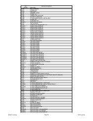
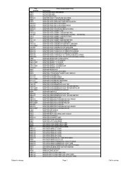
<strong>Service</strong> AssembliesAIR CHECK60002-34 .................AIR CHECK,#500,34” LONGBRINE LINE FLOW CONTROLS (BLFC)60022-12 .................BLFC,.125 GPM,5000/5600/900060022-25 .................BLFC,.25 GPM,5000/5600/900060022-50 .................BLFC,.50 GPM,5000/5600/900060022-100 ...............BLFC,1.0 GPM,5000/5600/900060022-12 .................BLFC,.125 GPM,5000/5600/900060022-25 .................BLFC,.25 GPM,5000/5600/900060022-50 .................BLFC,.50 GPM,5000/5600/9000BRINE LINE FLOW CONTROL WASHERS17307.......................WASHER,FLOW,.125 GPM12094.......................WASHER,FLOW,.25 GPM10759.......................LABEL,.5 GPM,1.5 LBS SALT/MIN12097.......................WASHER,FLOW,1.0 GPMBRINE VALVE60032.......................BRINE VALVE,4600/5600BYPASSES60040SS ..................BYPASS VALVE,5600,3/4” NPT, BLK GRIP.................................LEVER,STAINLESS STEEL60041SS ..................BYPASS VALVE,5600,1” NPT, BLK GRIP.................................LEVER,STAINLESS STEEL60049.......................3/4” BYPASS, PLASTICCOLLECTORS, UPPER18280.......................COLLECTOR,TOP,1” X .011,GRAY BAYONET18280-01 .................COLLECTOR,TOP,1” X .020,WHITE.................................WIDE SLOT BAYONET18280-02 .................COLLECTOR,TOP,1” X .008,RED.................................NARROW SLOT,BAYONETCOVER18260-00 .................COVER,FRONT,SMOKEDISTRIBUTORS60795-00 .................DISTRIBUTOR ASSY,1”,STD, GRAY,.011,.................................W/72”TUBE60795-01 .................DISTRIBUTOR ASSY,1”,WIDE, WHITE,..................................020,W/72”TUBE60795-02 .................DISTRIBUTOR ASSY,1” NARROW, RED..................................008, W/72” TUBEDRAIN LINE FLOW CONTROLS60705-XX ................DRAIN LINE FLOW CONTROL.................................(FROM .6 - 7.0 GPM)60706-XX ................DRAIN LINE FLOW CONTROL W/QUICK.................................CONNECT (FROM 8-15 GPM)60700-XX ................DRAIN LINE FLOW CONTROL (8-15 GPM)DRAIN LINE FLOW CONTROL WASHERS19153........................06 GPM19152........................08 GPM19151.......................1.0 GPM12085.......................1.2 GPM19150.......................1.3 GPM12086.......................1.5 GPM19149.......................1.7 GPM12087.......................2.0 GPM12088.......................2.4 GPM12089.......................3.0 GPM12090.......................3.5 GPM12091.......................4.0 GPM19147.......................4.5 GPM12092.......................5.0 GPM17814.......................6.0 GPM12408.......................7.0 GPM17943.......................8.0 GPM17944.......................9.0 GPM16529.......................10 GPM16735.......................12 GPM16736.......................15 GPMFLOATS60068-30 .................FLOAT ASSY,2310,W/30” RODMETER MODULE60626.......................METER ASSY,TURBINE,ELECTRONIC, 3/4”.................................WITH CLIPS AND SCREWS19797.......................METER ASSY,3/4” DUAL PORT,SLP,.................................ELEC,PLAS,TURB,W/O CLPS&SCRSINJECTORS (1610)18272-000 ...............#000 BROWN INJECTOR18272-00 .................#00 VIOLET INJECTOR18272-0 ...................#0 RED INJECTOR18272-1 ...................#1 WHITE INJECTOR18272-2 ...................#2 BLUE INJECTORPISTON60115-10 .................. PISTON ASSEMBLYSAFETY BRINE VALVE60014.......................2310 PLASTICSALES & SERVICE AIDS40734.......................SPEC SHEET40272.......................SERVICE MANUALSEALS & SPACERS60120.......................SEAL AND SPACER KITSERVICE EQUIPMENT12763.......................STUFFER TOOL ASSY,5600/900012874.......................HOOK,SEAL13061.......................PULLER ASSY,PORT RING16174.......................SILICONE GREASE, 2 OZ. TUBE16586-8 ...................SILICONE GREASE, 8 LB. PAIL41891.......................WRENCH, PLASTIC BY-PASSTIMER42739.......................TIMER ASSY, SXT, PROFLOYOKES13708.......................3/4” NPT13708-10 .................3/4” BSP13708NP ..................3/4” NPT, NICKEL PLATED13708-10NP ............3/4” BSP, NICKEL PLATED13708-45 .................3/4” SWEAT13708-45NP ............3/4” SWEAT, NICKEL PLATED13708-40 .................1” SWEAT13708-40NP ............1” SWEAT, NICKEL PLATED13398.......................1” NPT13398-10 .................1” BSP13398NP ..................1” NPT, NICKEL PLATED13398-10NP ............1” BSP, NICKEL PLATED18706.......................1” PLASTIC, MNPT18706-10 .................1” PLASTIC, MBSP18706-02 .................3/4” PLASTIC, MNPT18706-12 .................3/4” PLASTIC, MBSP19275.......................3/4” 90 DEG ANGLE, NPT19275-10 .................3/4” 90 DEG ANGLE, BSP19275NP ..................3/4” 90 DEG ANGLE, NPT, NICKEL PLATED19275-10NP ............3/4” 90 DEG ANGLE, BSP, NICKEL PLATED19275-45 .................3/4” 90 DEGANGLE SWEAT19275-45NP ............3/4” 90 DEG ANGLE SWEAT, NICKEL PLATED19620-01 .................90 DEG ADAPTER COUPLINGPage 43
P/N <strong>42773</strong> Rev. A 8/08