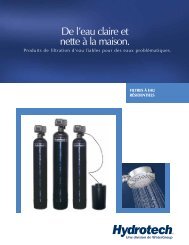
5600SE Valve - Hydrotech
5600SE Valve - Hydrotech
5600SE Valve - Hydrotech

Create successful ePaper yourself
Turn your PDF publications into a flip-book with our unique Google optimized e-Paper software.
<strong>5600SE</strong> <strong>Valve</strong>Iron & Sulfur FilterOperation ManualRead all instructions carefully before operation.#51404 03/05
<strong>Hydrotech</strong> Iron & Sulfur (Manganese Greensand) FilterPerformance and SpecificationsItem Model Pipe Max. Bed Iron removal Service Peak Backwash Mineral KMnO4 ShippingNumber Number Media Size Capacity Capacity Flow Rate Flow Rate Flow Rate Tank size Regeneration Weightcu. ft. (litres) inches (mm) (ppm) (ppm) USGPM (LPM) inches (mm) (oz) Lbs. (kg)7621 <strong>5600SE</strong>M-847IF 0.75 (21) 3/4 (19) 6000 4500 3.0 (7.6) 4.0 (15) 3.5 (13) 8 x 47 (203 x 1194) 2 120 (55)7622 <strong>5600SE</strong>M-948IF 1.00 (28) 3/4 (19) 8000 6000 3.0 (11) 5.0 (19) 4.0 (15) 9 x 48 (229 x 1219) 4 135 (61)7623 <strong>5600SE</strong>M-1054IF 1.50 (42) 3/4 (19) 12000 9000 5.0 (19) 8.0 (30) 5.0 (19) 10 x 54 (254 x 1372) 6 185 (84)Caution: These water conditioners are not intended to be used for treating water that is microbiologically unsafe or of unknown quality without adequatedisinfection before or after the system.Notes:Operating Temperature Range: 34° to 110°F (1° to 43°C)Operating Pressure Range: 20 to 120psi (137 to 827 kPa)Electrical: 24V/60Hz with a supplied 120V/60Hz Wall Mount CSA Approved Transformer1. The manufacturer reserves the right to make product improvements which deviate from thespecifications and descriptions stated herein without obligation to change previously manufacturedproducts or to note the change.2. Peak flow rates are intended for intermittent use only and are for residential application only.3. KMnO4 refers to Potassium Permanganate.How Your <strong>5600SE</strong> Water Filter WorksYour automatic iron filter is an ingeniously simple and reliable design. The unit consists of a bed of filter media containedin a fiberglass tank; a specially designed feeder containing potassium permanganate for the regeneration of the filterand a proven automatic control.Raw water enters your home through the main supply line, enters your iron filter and passes down through the filtermedia. Any iron, manganese or hydrogen sulfide present in your water supply is exposed to oxygen stored in the filtermedia. The oxygen causes precipitation of the minerals and they are trapped in the filter media. Only clean filtered waterflows to your household water line. The filter media is periodically regenerated, automatically backwashing the trappedminerals to the drain and replacing the oxygen. This is done by introducing potassium permanganate to the media.1. Your automatic iron filter can be programmed to operate according to your needs by making the appropriate settingson the timer. On the days your filter regenerates, the operating cycles will be automatically performed. In the serviceposition, filtered water is supplied for household use.2. The automatic control reverses the flow of the water through the filter, backwashing minerals trapped in the filter tothe drain.3. The control pulls a vacuum on the feeder. This causes an exact volume of saturated potassium permanganatesolution to be drawn into the filter tank.4. The control slowly rinses the chemical through the media tank. The potassium permanganate supplies oxygen to thefilter media.5. The control fast rinses the media bed to settle it and to ensure that all the chemical and mineral precipitate isremoved.6. The control adds water to entirely fill the previously evacuated feeder. The feeder is now ready for the nextregeneration. The control puts the system into service, supplying iron-free water to the household. All this isperformed automatically over a period of 2 ¾ hours. Water runs to the drain for approximately 80 minutes.1
In normal operation, the Time of Day display will alternate being viewed with the Volume Remaining display. This displaywill be in gallons. As treated water is used, the Volume Remaining display will count down from a maximum value to zeroor (---). Once this occurs, a regeneration cycle will be initiated at the Set Regeneration Time. Water flow through the valveis indicated by the Flow Dot that will flash in direct relationship to flow rate.Example833 Gallons of TreatedWater RemainingServiceProgram833 FlowP.M.• •0 Gallons of TreatedWater RemainingServiceProgram•- - - •FlowP.M.In regeneration, the control will display a special regeneration display. In this display, the control will show the currentregeneration step number the valve is advancing to or has reached and the time remaining in that step. The stepnumber displayed will flash until the valve has completed driving into this regeneration step position. Once allregeneration steps have been completed, the valve will return to Service and resume normal operation.ExampleLess than 6 minutesremaining in RegenStep #1ServiceProgram1 - - 5Pushing the Extra Cycle Button during a regeneration cycle will immediately advance the valve to the next cycle stepposition and resume normal step timing.FlowP.M.Control Operation During ProgrammingThe control will only enter the Program Mode with the valve in Service. While in the Program Mode, the control willcontinue to operate normally, monitoring water usage and keeping all displays up to date. Control programming is storedin memory permanently, eliminating the need for battery back-up power.Control Operation During a Power FailureDuring a power failure, all control displays and programming will be stored for use upon power re-application. Thecontrol will retain these values for years, if necessary, without loss. The control will be fully inoperative and any calls forregeneration will be delayed. The control will, upon power re-application, resume normal operation from the point whereit was interrupted. An indication that a power outage has occurred will be an inaccurate Time of Day display.2
Sizing and Operating RequirementsWater PressureThe water system must have a pump big enough to deliver the recommended backwash rate with a minimum pressure at the inlet ofthe filter of 20 psi (137 kPa). If the existing system cannot do this, it must be upgraded to do so. Whenever possible, the water systemshould be adjusted to deliver at least 30 psi (206.8 kPa) for even more satisfactory results. Maximum pressure should not exceed 100psi (689 kPa).Backwash Flow RatesThe most important criteria in sizing an iron filter is the capacity of the pump. The water must pass through the filter media at aservice flow rate that allows it to oxidize and collect the iron. The filter must also be backwashed at a flow rate sufficient to dislodgeand remove the captured iron. Failure to provide sufficient water will cause a build-up of iron in the filter media, impairing its ironremoving ability and resulting in iron bleeding out into the service water.In order for your filter to backwash and rinse properly, your pump must be capable of providing the backwash flow rates indicated inthe above specification chart.CapacityAn iron filter with one cubic foot of filter media regenerated with one Potassium Permanganate feeder will work well for mostresidential applications. For example, with iron in the range of 3-6 ppm, most filters will need to regenerate every two or three daysproviding an average family size of four or five people.The specification chart above shows the iron removal capacity in ppm that can be expected on automatic iron filters. Thespecifications are based on obtaining 6,000 ppm of capacity for each cubic foot of filter media. Two different Potassium Permanganatefeeders are available – one feeding 2 oz. per regeneration, the other feeding 4 oz.In order to obtain the above capacities, the pH of the water being treated must be 7.0 or above. In the event the water is below 7.0, itmust be treated with the appropriate equipment before going through the filter.Removal of Iron, Manganese & Hydrogen SulfideFor the purpose of sizing a filter, consider 1 ppm of manganese equal to 2 ppm of iron and 1 ppm of hydrogen sulfide equal to 3 ppmof iron. Manganese and hydrogen sulfide (sulfur) are more difficult to oxidize than iron. Therefore, we suggest that, when making yoursizing calculations and regeneration frequency calculations, calculate iron x 1, manganese x 2 and hydrogen sulfide x 3. All threemust equal less than 10 ppm. Manganese is often present in water when iron is present. Hydrogen sulfide can normally be identifiedby a strong rotten egg odor.Installation InstructionsAll government codes and regulations governing the installation of these devices must be observed.CAUTION: If the ground from the electrical panel or breaker box to the water meter or underground copper pipe is tied to the copperwater lines and these lines are cut during installation of the Noryl bypass valve and/or poly pipe, an approved grounding strap mustbe used between the two lines that have been cut in order to maintain continuity. The length of the grounding strap will depend uponthe number of units being installed and/or the amount of copper pipe being replaced with poly. See Figure 1.In all cases where metal pipe was originally used and is later interrupted by poly pipe or the Noryl bypass valve as in Figure 1 or byphysical separation as in Figure 2, an approved ground clamp with no less than #6 copper conductor must be used for continuity, tomaintain proper metallic pipe bonding.Check your local electrical code for the correct clamp and cable size.Figure 1Electrical PanelFigure 2Ground StrapCopper PipeOutside Water Line For Outside & 3rd Tap Comes From MeterGroundFromPanelPoly PipePoly PipeFilterc/w Plastic BypassWater MeterUnfiltered Water BypassLoop Cut & CappedFiltered Water Line in HomeGround Strap RequiredBecause of Break in Continuity3
1. Place the iron filter and the chemical feeder container on a flat surface in desired location, near a drain and 120 volt ACoutlet. Subjecting your filter to freezing or to water temperatures above 110°F (43°C) will void the warranty.NOTE: Some units are shipped with the media bed in separate bags. To install, unscrew the control valve from the top ofthe fiberglass tank, position the riser tube in the center of the tank plugging the tube with a cloth and pour the media intothe tank in the following order: coarse, fine gravel and then the filter media. Remove the cloth and carefully screw thevalve into the tank (When replacing the media, the tank must first be inverted and the old media bed removed. Seeinstructions provided with the replacement media).Rural Well Supply - Iron & Hardness Removal2. Attach the installation kit or bypass to the control valve. Make the inlet and outlet connections to meet applicableplumbing codes. A 3/4” inlet line is recommended. When sweat fittings are used, solder the adapters for the inlet andoutlet to a short length of copper pipe first. This procedure is necessary because the controls MUST NOT be subjectedto temperatures above 160°F (71°C). Then, using Teflon tape, screw the adapters for the inlet, outlet and drain into thevalve.CAUTION: Do not use pipe thread compound as it may attack the material in the valve body.3. On the drain, use the 1/2" hose barb supplied and a full 1/2" ID hose (not supplied) for the drain line and make theshortest run to a suitable drain. The drain lines must be secured in position at the ends which discharges into the drainso it cannot be inadvertently moved from the drain, resulting in chemical spillage.4. Connect the feeder container to the control valve with the flexible polyethylene tubing provided. The connection to thecontainer is made with the fitting nut provided (do not overtighten).5. Attach the 5/8” hose (supplied) to the over flow fitting on the feeder and run the hose to the floor drain.6. Make sure the bypass valve is in the service position.7. Plug the 24-volt transformer into a 120 VAC 60 Hz outlet. This valve has four positions: 1) Backwash 2) Brine/Rinse3) Rapid Rinse and 4) Brine Refill. When the valve is in the Service position, the extra cycle button (far left button asshown on Figure 4) must be pressed and held for 5 seconds before it activates. Press and hold the extra cycle button for5 seconds to advance the valve to the “1” Backwash position. Slowly turn on the water supply and allow the unit tobackwash until the air purges out of the tank and clears the system.8. Advance to the brine refill position “4”. Allow to fill for 5 minutes. Make sure there are no leaks in the top connection tothe feeder container.9. Advance to the Brine/Rinse position “2”. Proper draw is indicated by upward motion of water droplets in the tubeconnected to the feeder container. Allow to draw for 5 minutes to pull the air out of the feeder container.10. Put control into the service position.11. Set the time of day and gallons between regeneration following the information on Pages 5-8.12. Make sure any bypass is in the service position.13. Cautiously pour the Potassium Permanganate into the feeder and replace the cover and safety screws. (See the refillinginstructions on page 10).14. Manually initiate regeneration after about one hour for the potassium permanganate to activate the manganesegreensand.ALL STATE AND LOCAL GOVERNMENT CODES GOVERNING INSTALLATIONS OF THESE DEVICES MUST BE OBSERVED.4
Operating InstructionsService Indicator:<strong>Valve</strong> in Service - Dot OnExtra Cycle Tonight - Flashing DotSet Up ButtonFlow Indicator:Flashing Dot With Water FlowP.M. IndicatorSet Down ButtonFigure 3The valve has been pre-programmed with factory settings as follows:Regeneration Cycle Step Programming1. Backwash ..................................10 minutes2. Brine Rinse..................................50 minutes3. Rapid Rinse ................................10 minutes4. Brine Refill ..................................4 minutesInstallation Tip: The <strong>5600SE</strong> Filter should not be allowed to regenerate at the same time as any other watertreatment units. If adjustment is required, consult programming chart to adjust default regeneration time.Default setting is 11:00 pm.)5
Operating InstructionsWhenever the valve is in Service the current time of day can be set, the control programmed, or an extraregeneration initiated at any time.Service Indicator:<strong>Valve</strong> In Service - Dot OnExtra Cycle Tonight - Flashing DotSet Up ButtonFlow Indicator:Flashing Dot with Water FlowP.M. IndicatorSet Down ButtonPush either the Up or Down Set Button once to adjust Time of Day Display by one digit.Push and hold either Up or Down Set Button to adjust Time of Day Display by several digits.Program Mode Indicator:Program Mode Entered - Dot OnExtra Cycle Button1. Push and hold for 5 seconds both the Up and Down Set Buttons to enter Programming Mode.2. Push the Extra Cycle Button once per display until all have been viewed and this mode is exited andnormal operation is resumed.6
Program Mode Indicator:Program Mode Entered - Dot OnExtra Cycle ButtonSet UpButtonSet DownButton1. The first option setting display that appears in the Program Mode is Treated Water Capacity. Using theSet Up or Down Buttons, set the amount of treated water that can flow through the unit before aregeneration is required. For Example:650 Gallons CapacityServiceProgram• 650FlowP.M.2. Push the Extra Cycle Button. The second option setting display that appears is Regeneration Time. Usingthe Set Up or Down Buttons, set the desired time of day when a regeneration can occur, is required. ForExample:2:00 A.M. Regeneration TimeServiceProgram•2:00FlowP.M.3. Push the Extra Cycle Button. The third option setting display that appears is Regeneration Day Override.Using the Set Up or Down Buttons, set the maximum number of days before a regeneration cycle mustoccur. For Example:Regenerate Every7 Days MinimumServiceProgram• A--7FlowP.M.This is an option only. Please do not adjust before consulting an authorized dealer.7
To determine the frequency of regeneration, use this procedure:Days:Total amount of iron to be removed between regenerations -÷ ppm of iron to be removed per day= NUMBER OF DAYS BETWEEN REGENERATIONSExample:5 people in the householdx 60 gallons of filtered water per person= 300 gallons of filtered per dayx 8 ppm of iron= 2400 PPM OF IRON TO BE REMOVED PER DAYUsing 5600 SEM-948IF + 1 Feeder6000 ppm capacity÷ 2400 ppm to be removed per day= 2 DAYS BETWEEN REGENERATIONSSetting the Frequency of Automatic Regeneration (SE Models)The number of gallons of filtered water your iron filter can supply between regenerations must first bedetermined using the following calculations.Gallons:ppm of capacity between regenerations (see Specifications - Page 1)÷ ppm of iron in the water sample*= number of gallons supplied between regenerations- reserve capacity (number of people x 60 gallons)Example - Using 5600 SEM-948IF + 1 Feeder6000 ppm between regenerations÷ 8 ppm of iron= 750 gallons between regenerations- 300 gallons reserve capacity (5 people x 60 gallons)= 450 GALLONS - BETWEEN REGENERATIONS* 1 ppm of manganese = 2 ppm of iron; 1 ppm of hydrogen sulfide = 3 ppm of iron8
Manual Regeneration CycleIf you run out of filtered water because of inadequate regeneration frequency, inadequate reserve capacity, power failureor unusually high water usage, you can initiate a manual regeneration simply by pressing the extra cycle button. Thefilter will now automatically complete a regeneration cycle and return to service. If possible, avoid water use during theregeneration cycle.Once you have set your filter you may experience frequent loss of water pressure, you may have to increase thefrequency of regeneration by decreasing the number of gallons between regeneration.Potassium Permanganate FeederThe potassium permanganate feeder assembly incorporates a non-pressurized storage tank and innovative new griddesign along with a dependable float valve.The attractive 10" x 16" black tank is made of touch blow-molded high density polyethylene. It has a potassiumpermanganate capacity of 30 lbs. and a liquid capacity of 5 gallons.The black injection molded cover is securely fastened with three stainless steel safety screws to prevent access bychildren and pets. Also, the potassium chemical tank should be placed where it is free from possible upset or access bychildren or pets.Chemical warning label and drain caution label are affixed to unit.The unique polypropylene grid pad refuses to allow even the finest grade of undissolved potassium permanganate topass through the grid. This permits efficient use of our assembly with all grades of potassium permanganate. Standardgrid platform height is 6". Additional heights are available - consult factory.9
The unit is shipped fully tested and assembled and weighs approximately 7 lbs. The feeder assembly includes:10” x 16 “ black tank Black injection molded cover3 Stainless steel safety screws Grid with polypropylene grid pad4” Well and cap Float valve15 ft of 5/8” x 1/2” poly drain tubing* Chemical warning labelDrain caution label4 ft of 1/4” or 3/8” suction tubing1/4” PVC riser pipe 1/2” Overflow fitting1/4” or 3/8” poly tube elbowThe potassium storage tank placement should be such to permit the installation of the overflow line to a permanent drainfacility.To<strong>Valve</strong>Poly TubeElbowSafety ScrewsLocation ofWarningLabelLocation ofThree SafetyScrews2 PieceOverflowDry PotassiumPermanganateStoragePolypropyleneGrid PadWet PermanganateSolution1_” Min.To ApprovedDrainLocation ofDrain LabelToApprovedDrainPolyethyleneGrid Plate &SupportsDimensions - InchesA = 16-1/2” E = See TableB = 14-1/2” F =5-3/4” (2 oz. to 4 oz.)C = 10-1/2” 7-5/8” (6 oz.)D = 5-1/4” G = 10-1/2”H = 1/8”Correct water temperature is important for obtaining properly dissolved potassium permanganate.Tables based on permanganate solubility of 4 oz/gal at 50°F or 8 oz/gal at 72°F.Float setting is based on distance between brine valve top body nut and the bottom of the float with the valve in the closed (float up) position.All dimensions nearest 1/4 inch.Iron and Manganese RemovalOz. Of Potassium Gallons of Float Riser PipePermanganate Solution Setting Length2 3/4 2-1/2 114 1 4 12-1/26 1-1/2 5-5/8 12-1/2A recommended dose of 2 oz. to 6 oz. of potassium permanganate per cubic foot of manganese greensand issuggested for regeneration. Correct water temperature is important in obtaining proper dissolving of potassiumpermanganate. At 50°F (10°C), 4 oz. of potassium permanganate can dissolve in one gallon of water. At roomtemperature 72°F (22°C), 8 oz. will dissolve in one gallon of water.10
Operating InstructionsSoundsYou will notice new sounds as your filter operates such as the hum of the timer or click of the actuator arm. Duringregeneration, it will not be uncommon to hear the sounds of water running to the drain.Manual Bypass (Figure 4)In case of an emergency you can isolate your water filter from thewater supply using the bypass valve located at the back of thecontrol.In normal operation the bypass is open with the ON/OFF knobs inline with the INLET and OUTLET pipes. To isolate the filter, simplyrotate the knobs clockwise (as indicated by the word BYPASS andarrow) until they lock.You can use your water related fixtures and appliances as the watersupply is bypassing the filter. However, the water you use will beuntreated.To resume filtered water service, open the bypass valve by rotatingthe knobs counter-clockwise.Figure 4OUTLETINLETMaintenance InstructionsMaintenance of your new water filter requires very little time or effort but it is essential. Regular maintenance will ensuremany years of efficient and trouble free operation.PLEASE NOTE: THE FOLLOWING MAINTENANCE PROCEDURES MUST BE PERFORMEDREGULARLY FOR YOUR GUARANTEE TO BE VALID.Cleaning The Injector Assembly (Figure 5)The presence of iron and sediment will restrict and clogthe injector assembly which is located on the right handside of the control valve. This assembly is easy to clean.Shut off the water supply to your unit and reduce thepressure by turning the large knob to backwash. Using ascrewdriver, remove the two screws holding the injectorassembly to the control valve body. Carefully remove theassembly and disassemble.The injector nozzle is removed for the injector body bycarefully turning it out with a large screwdriver. Carefullyflush all parts with water. Use a mild acid such as vinegaror Iron Out to clear the small holes in the nozzle andthroat. Reassemble using the reverse procedure.Figure 5Care Of Your FilterYour filter tank and chemical feeder container can be cleaned with a mild soap solution. Never subject the unit tofreezing. Do not strike or drop the chemical feeder container. If the container is found to be leaking, shut off the watersupply to your filter and replace the container at once.11
Trouble Shooting GuidePROBLEM CAUSE CORRECTION1. Filter fails to regenerate or A. Electrical service to unit has A. Assure permanent electrical serviceregenerates at wrong times been interrupted (check fuse, plug or switch)B. Timer is defective B. Repair or replace timerC. Power failure C.Reset time of dayD. Timer motor does not run D.Replace defective motor2. Filter bleeds iron or odor A. Bypass valve is open A. Close bypass valveB. Container is depleted B. Replace or refill containerC. Excessive water usage C.Increase frequency of regenerationand/or settings. Make sure there are noleaks in toilets and sinksD. Insufficient water flowing into D.Check refill setting. Check for pluggedchemical containercontainer tube and flow controlE. Hot water tank rusty E. Repeated flushings of the hot water tankare required. Do not use hot water duringregenerationF. Leak at distributor tube F. Make sure distributor tube is not cracked.Check O-ring and tube pilotG. Defective or stripped media bed G. Replace mediaH. Not backwashing enough H.Be sure flow control is not clogged ordrain line restricted. Be sure waterpressure has not dropped and that pumphas sufficient capacity.I. Internal valve leak I. Replace seals and spacers and/or pistonJ. Electrical Service to unit has J. Assure permanent electrical service(check been interrupted fuse, plug orswitch)K. Control will not draw chemical K. Maintain water pressure at 20 psi (139.9properly (see below)kPa) minimum. Clean or replace injectorassembly. Check for air leaks along brineline and tighten all connections.L. Quality of water has worsened L. Have water sample analysed todetermine any changeM. Filter capacity is too small M.Replace with larger unit3. Filter regenerates every day A. Faulty gear train A. Check the mechanical linkage on thetimer control to eliminate possible bindingin the gear train.4. Iron filter uses too much A. Defective chemical container A. Replace containerchemical5. Loss of water pressure A. Iron or turbidity build-up in filter A. Increase frequency of regeneration sofilter backwashes more often. NOTE:Make sure filter is sized large enough tohandle water usageB. Inlet to control blocked with iron B. Clean inlet line. Remove piston and cleanbuild-up or foreign matter control.6. Loss of media through line A. Air in water system A. Assure that well system has proper aireliminator control. Check for dry wellcondition.B. Backwash rate too fast B. Check drain flow control for proper flowrate12
Trouble Shooting Guide Cont’dPROBLEM CAUSE CORRECTION7. Iron filter fails to draw A. Drain line flow control is A. Clean drain line flow controlchemicalpluggedB. Injectors and/or screen plugged B. Clean or replace injectors and/or screenC. Line pressure is too low C.Maintain line pressure at 20 psi (139.9kPa) minimumD. Internal control leak D.Change seals and spacers and/or pistonassembly8. Drain flows continuously A. Foreign material in control A. Remove piston assembly and inspectbore, remove foreign material and checkcontrol in various regeneration positionsB. Internal control leak B. Change seals and spacers and/or pistonassemblyC. Control valve jammed in brine C.Replace piston and seals and spacersor backwash position(and drive motor if necessary)D. Timer motor stopped or jammed D.Replace timer motor9. Pink color (potassium A. Poor water pressure or A. Be sure pump is set at 20 psi (139.9permanganate) present insufficient pump capacity kPa) minimum and is capable ofafter regeneration; medicinalwater tasteproducing 5 - 12 USGPM accordingto filter sizeB. Chemical in water supply B. Decrease frequency of regeneration13
GUARANTEEHYDROTECH guarantees that your new water conditioner is built of quality material and workmanship. When properlyinstalled and maintained, it will give years of trouble-free service.FIVE YEAR COMPLETE PARTS GUARANTEEHYDROTECH will replace any part which fails within 60 months from date of manufacture, provided the failure is due to adefect in material or workmanship. The only exception shall be when proof of purchase or installation is provided and thenthe warranty period shall be from the date thereof.TEN YEAR GUARANTEE ON MINERAL TANKSHYDROTECH will provide a replacement mineral tank to any original equipment purchaser in possession of a tank that failswithin 120 months, provided that the water conditioner is at all times operated in accordance with specifications and notsubject to freezing or exposure to direct sunlight.GENERAL PROVISIONSHYDROTECH assumes no responsibility for consequential damage as a result of escaped water from the water filter; laboror expense incurred as a result of a defect or for failure to meet the terms of these guarantees because of circumstancesbeyond its control.WaterGroup Inc. WaterGroup Companies Inc.Fridley, Minnesota Regina, SaskatchewanSun Valley, California Cambridge, Ontario1-800-354-7867 1-877-299-5999www.hydrotechwater.comPrinted in Canada