ProFloSXT Upflow Service Manual 42773 - Pentair Residential ...
ProFloSXT Upflow Service Manual 42773 - Pentair Residential ...
ProFloSXT Upflow Service Manual 42773 - Pentair Residential ...

Create successful ePaper yourself
Turn your PDF publications into a flip-book with our unique Google optimized e-Paper software.
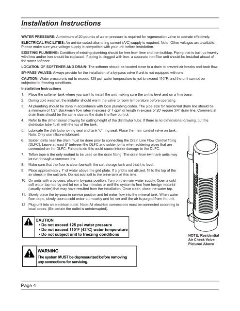
Installation InstructionsWATER PRESSURE: A minimum of 20 pounds of water pressure is required for regeneration valve to operate effectively.ELECTRICAL FACILITIES: An uninterrupted alternating current (A/C) supply is required. Note: Other voltages are available.Please make sure your voltage supply is compatible with your unit before installation.EXISTING PLUMBING: Condition of existing plumbing should be free from lime and iron buildup. Piping that is built up heavilywith lime and/or iron should be replaced. If piping is clogged with iron, a separate iron filter unit should be installed ahead ofthe water softener.LOCATION OF SOFTENER AND DRAIN: The softener should be located close to a drain to prevent air breaks and back fl ow.BY-PASS VALVES: Always provide for the installation of a by-pass valve if unit is not equipped with one.CAUTION: Water pressure is not to exceed 125 psi, water temperature is not to exceed 110°F, and the unit cannot besubjected to freezing conditions.Installation Instructions1.2.3.4.5.6.7.8.9.Place the softener tank where you want to install the unit making sure the unit is level and on a firm base.During cold weather, the installer should warm the valve to room temperature before operating.All plumbing should be done in accordance with local plumbing codes. The pipe size for residential drain line should bea minimum of 1/2”. Backwash flow rates in excess of 7 gpm or length in excess of 20’ require 3/4” drain line. Commercialdrain lines should be the same size as the drain line flow control.Refer to the dimensional drawing for cutting height of the distributor tube. If there is no dimensional drawing, cut thedistributor tube flush with the top of the tank.Lubricate the distributor o-ring seal and tank “o” ring seal. Place the main control valve on tank.Note: Only use silicone lubricant.Solder joints near the drain must be done prior to connecting the Drain Line Flow Control fitting(DLFC). Leave at least 6” between the DLFC and solder joints when soldering pipes that areconnected on the DLFC. Failure to do this could cause interior damage to the DLFC.Teflon tape is the only sealant to be used on the drain fitting. The drain from twin tank units maybe run through a common line.Make sure that the floor is clean beneath the salt storage tank and that it is level.Place approximately 1” of water above the grid plate. If a grid is not utilized, fill to the top of theair check in the salt tank. Do not add salt to the brine tank at this time.10. On units with a by-pass, place in by-pass position. Turn on the main water supply. Open a coldsoft water tap nearby and let run a few minutes or until the system is free from foreign material(usually solder) that may have resulted from the installation. Once clean, close the water tap.11. Slowly place the by-pass in service position and let water flow into the mineral tank. When waterflow stops, slowly open a cold water tap nearby and let run until the air is purged from the unit.12. Plug unit into an electrical outlet. Note: All electrical connections must be connected according tolocal codes. (Be certain the outlet is uninterrupted).NOTE: <strong>Residential</strong>Air Check ValvePictured AbovePage 4