ProFloSXT Upflow Service Manual 42773 - Pentair Residential ...
ProFloSXT Upflow Service Manual 42773 - Pentair Residential ...
ProFloSXT Upflow Service Manual 42773 - Pentair Residential ...
Create successful ePaper yourself
Turn your PDF publications into a flip-book with our unique Google optimized e-Paper software.
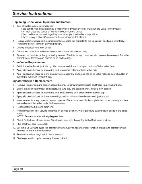
<strong>Service</strong> InstructionsReplacing Brine Valve, Injectors and Screen1.2.3.4.5.Turn off water supply to conditioner:If the conditioner installation has a “three valve” bypass system, fi rst open the valve in the bypassline, then close the valves at the conditioner inlet and outlet.If the conditioner has an integral bypass valve, put it in the Bypass position.If there is only a shut-off valve near the conditioner inlet, close it.Relieve water pressure in the conditioner by stepping the control into the Backwash position momentarily.Return the control to the In <strong>Service</strong> position.Unplug electrical cord from outlet.Disconnect brine tube and drain line connections at the injector body.Remove the two injector body mounting screws. The injector and brine module can now be removed from thecontrol valve. Remove and discard brine body o-rings.Brine Valve Replacement1.2.3.Pull brine valve from injector body. Also remove and discard o-ring at bottom of brine valve hole.Apply silicone lubricant to new o-ring and reinstall at bottom of brine valve hole.Apply silicone lubricant to o-ring on new valve assembly and press into brine valve hole. Be sure shoulder onbushing is fl ush with injector body.Injectors/Screen Replacement1.2.3.4.5.6.7.8.9.Remove injector cap and screen, discard o-ring. Unscrew injector nozzle and throat from injector body.Screw in new injector throat and nozzle, be sure they are sealed tightly. Install a new screen.Apply silicone lubricant to new o-ring and install around oval extension on injector cap.Apply silicone lubricant to three new o-rings and install over three bosses on injector body.Insert screws thorough injector cap and injector. Place this assembly thorough hole in timer housing and intomating holes in the valve body. Tighten screws.Reconnect brine tube and drain line.Return bypass or inlet valving to normal In <strong>Service</strong> position. Water pressure automatically builds in the conditioner.NOTE: Be sure to shut off any bypass line.Check for leaks at all seal areas. Check drain seal with the control in the Backwash position.Plug electrical cord into outlet.10. Set Time Of Day and cycle the control valve manually to assure proper function. Make sure control valve isreturned to the In <strong>Service</strong> position.11.Be sure there is enough salt in the brine tank.12. Start regeneration cycle manually if water is hard.Page 40


