

DevKit1207 Evaluation Kit
DevKit1207 Evaluation Kit
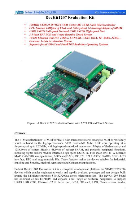
DevKit1207 Evaluation Kit

You also want an ePaper? Increase the reach of your titles
YUMPU automatically turns print PDFs into web optimized ePapers that Google loves.
• IrDA transceiverInput Interface and Other Facilities• 1 x Potentiometer (A/D converter)• 2 x USER buttons• 1 x RESET button• 1 x WAKEUP button• 20-pin standard JTAG interface• G-sensor 3-Axis Acceleration Sensor• RTC battery socket (User needs to prepare battery, CR1220 model is recommended)• 1 x LED for Power indicator• 2 x LEDs for USB OTG FS indicators• 2 x LEDs for USB OTG HS indicators• 4 x User LEDs• 140 GPIO pins are all brought outMechanical Parameters• Dimensions: 160 mm x 115 mm• Input Voltage: +5V• Power consumption: 0.4A@5V• Working Temp.: -10 ℃ ~ 70 ℃• Humidity Range: 20% ~ 90%Camera Interface USB OTG_FS USB OTG_HS RTC battery LCD/Touch ScreenGPIO pinsInterfaceIrDAIrDAConfigurationTF cardConfigurationTF card slotSTM32F207IGT6PotentiometerUser KeysG-sensorModuleWakeupResetJTAGInterfacePower InBootloaderConfigurationEthernetSerial portConfigurationSerial portCANSpeakerAudio OutNote: RTC battery is not provided in default deliveries, user needs to prepare it yourself, Typemodel CR1220 is recommended. Some functions need to use Jumpers to configure before using.Figure 1-2 <strong>Dev<strong>Kit</strong>1207</strong> <strong>Evaluation</strong> Board3
Function Block DiagramFigure 1-3 <strong>Dev<strong>Kit</strong>1207</strong> Function Block Diagram4
SoftwareFeaturesThe <strong>Dev<strong>Kit</strong>1207</strong> <strong>Evaluation</strong> <strong>Kit</strong> software mainly features as below:• Supports for uC/OS-II_v2.86 and FreeRTOS_v6.1.0 real-time operating systems• Supports UCGUI_v3.90a• Supports FatFs_vR0.08a file system• Supports LWIP _v1.3.2 protocol stack• Provided with plenty of software examplesBoot ModesThe <strong>Dev<strong>Kit</strong>1207</strong> <strong>Evaluation</strong> Board is able to boot from CPU internal system memory orembedded SRAM, user needs to configure the boot pins to select the mode. The boot loader islocated in system memory. It is used to reprogram the Flash memory by using Serial port or USBOTG FS in Device mode through DFU (device firmware upgrade).Drivers and Software examplesEmbest has provided complete drivers and software examples for this kit. User can demonstrateand test each software example and observe the result from LCD which would be easy tounderstand.The software examples mainly include following parts:Table 1-1• Examples for Basic peripherals drivers (see Table 1-1 below)IP/ModuleADCCANCRCNameADC3_DMADualADC_Interleaved_DMAmode3DualADC_RegulSimu_DMAmode1TripleADC_Interleaved_DMAmode2LoopBackNetworkingCRC_ExampleExampleBrief DescriptionHow to use ADC3 and DMA to continously transfer converteddata from ADC3 to the memory.How to use the ADC peripheral to convert a regular channel inDual interleaved mode using DMA in mode 3 with 5Msps.How to use the ADC peripheral to convert regularchannels simultaneously in dual mode using DMA inmode 1.How to use the ADC peripheral to convert a regular channel inTriple interleaved mode using DMA in mode 2 with 6Msps.How to set a communication with the CAN in loopback mode.how to configure the CAN peripheral to send and receive CANframes in normal mode. The sent frames are used to controlLeds by pressing key push button.How to use CRC (cyclic redundancy check) calculation unit toget a CRC code of a given buffer of data word (32-bit), basedon a fixed generator polynomial (0x4C11DB7).5
DACDMADAC_SignalsGenerationFLASH_RAMHow to use the DAC peripheral to generate several signalsusing DMA controller.How to use a DMA channel to transfer a word data buffer fromFLASH memory to embedded SRAM memory.EXTI EXTI_Example How to configure external interrupt lines.FLASHGPIOI2CProgramWrite_ProtectionIOToggleJTAG_RemapEEPROMGSensor-LIS33DEHow to program the STM32F2xx FLASH.How to enable and disable the write protection for theSTM32F2xx FLASH.GPIO ports are connected on AHB bus, using BSRRH andBSRRL registers one cycle is required to set a pin and anothercycle to reset it. So GPIO pins can toggle at AHB clockdivided by 2.How to use the JTAG/SWD IOs as standard GPIOs and gives aconfiguration sequence.How to use the I2C firmware library and an associate I2CEEPROM driver to communicate with an I2C EEPROMdevice.3-Axis Acceleration Sensor testing exampleI2S Audio How to play an audio file through the I2S peripheral.IWDGIWDG_ExampleHow to update at regular period the IWDG reload counter andhow to simulate a software fault generating an MCU IWDGreset on expiry of a programmed time period.LCD-Touch STMPE811QTR LCD and Touch screen application testing exampleLib-DEBUGNVICPWRLib_DEBUG_ExampleDMA_WFIModeIRQ_PriorityVectorTable_RelocationBORCurrentConsumptionPVDHow to declare dynamic peripherals pointers used for Debugmode.How to enter the system to WFI mode with DMA transferenabled and wake-up from this mode by the DMA End ofTransfer interrupt.How to use the Nested Vectored Interrupt Controller (NVIC)and configure their priorities.How to relocate the CortexM3 vector table in a specificaddress other than the default Flash memory base address.How to configure the programmable BOR thresholds using theFLASH option bytes.How to configure the STM32F2xx system to measure differentLow Power modes current consumption.How to configure the programmable voltage detector using anexternal interrupt line.6
RCCRNGRTCSDIOSysTickTIMSTANDBYSTOPRCC_ExampleRNG_MultiRNGBKP_DomainHW_CalendarTimeStampuSDCardSysTick_Example6StepsInputCaptureOCActiveOCInactiveOCToggleOnePulseParallel_SynchroPWM_InputPWM_OutputHow to enter the system to STANDBY mode and wake-upfrom this mode using: external RESET, RTC Alarm A orWKUP pin.How to enter the system to STOP mode and wake-up from thismode using RTC Wakeup Timer Event connected to EXTILine 22.How to use, for debug purpose, the RCC_GetClocksFreqfunction to retrieve the current status and frequencies ofdifferent on chip clocks.How to use the RNG peripheral to generate Random 32bitnumbers.How to use the peripherals available on Backup Domain.How to setup the RTC peripheral, in terms of prescaler andinterrupts, to be used to keep time and to generate alarminterrupt.How to use the RTC peripheral and the Time Stamp feature.How to use the SDIO firmware library and an associate driverto perform read/write operations on the SD Card memoryHow to configure the SysTick to generate a time base equal to1 ms.How to configure the TIM1 peripheral to generate 6 Steps.How to use the TIM peripheral to measure the frequency of anexternal signal.How to configure the TIM peripheral to generate four differentsignals with four different delays.How to configure the TIM peripheral in Output CompareInactive mode with the corresponding Interrupt requests foreach channel.How to configure the TIM3 peripheral to generate fourdifferent signals with four different frequencies.How to use the TIM peripheral to generate a One pulse Modeafter a Rising edge of an external signal is received in TimerInput pin.How to synchronize TIM peripherals in parallel mode.How to use the TIM peripheral to measure the frequency andduty cycle of an external signal.How to configure the TIM peripheral in PWM (Pulse WidthModulation) mode.7
USARTWWDGTIM1_SynchroTIM9_OCToggleTIM10_PWMOutputTimeBaseUSART_IRDAUSART_PrintfWWDG_ExampleHow to synchronize TIM1 and Timers (TIM3 and TIM4) inparallel mode.How to configure the TIM9 peripheral to generate fourdifferent signals with four different frequencies.How to configure the TIM peripheral in PWM (Pulse WidthModulation) mode.How to configure the TIM peripheral in Output CompareTiming mode with the corresponding Interrupt requests foreach channel in order to generate 4 different time bases.How to use IrDA to transmit and receive data.How to retarget the C library printf function to the USART.How to update at regular period the WWDG counter and howto simulate a software fault generating an MCU WWDG reseton expiry of a programmed time period.• Application example for G-sensor• Application example for SD card supporting FatFs_vR0.08a file system• Application example for USB Host/Device/OTG (see Table 1-2 below)Table 1-2USB Device application examplesNameAUDIODFUDualCoreHIDMSCVCPBrief DescriptionUse board as audio device, similar to USB acoustics, user can play music on PC and output soundthrough boardUse board as DFU device, user can use it for system firmware updating.Dual-USB channel testing example. Use HS-USB as MSC device and FS-USB as HID device.Use board as HID (Human Interaction Device) to implement USB mouse operation.Use board as MSC (Mass Storage Device) to implement data exchange between USB Host andboard.Use board as VCP (Virtual COM Port), user can regard board as a USB-to-COM moduleUSB OTG application examplesNameDRDBrief Description<strong>Dev<strong>Kit</strong>1207</strong> board can be used as either USB Host or USB DeviceUSB Host application examplesNameBrief Description8
DualCoreHIDMSCDual-USB channel testing example, use HS-USB as MSC (Mass Storage Device) host andFS-USB as HID (Human Interaction Device) host.Use board as HID (Human Interaction Device) host and can recognize USB mouse and USBkeyboard.Use board as MSC (Mass Storage Device) and can recognize U disk and other mobile storagedevices.Table 1-3• Application example for Ethernet on FreeRTOS/Non-OS/LWIP v1.3.2 protocol stack(see Table 1-3 below)Application example for Ethernet on FreeRTOS and LWIP v1.3.2 protocol stackNamehttpserver_netconnhttpserver_socketudptcp_echo_server_netconnBrief DescriptionWebserver application example based on netconnWebserver application example based on socketTCP/UDP Echo application example based on netconn 的 TCP/UDPApplication example for Ethernet on Non-OS and LWIP v1.3.2 protocol stackNamehttpservertcp_echo_clienttcp_echo_servertftpserverudp_echo_clientudp_echo_serverBrief DescriptionWebserver application exampleSimple Echo application example of Tcp clientSimple Echo application example of Tcp serverTftpserver application exampleSimple Echo application example of dup clientSimple Echo application example of server• Application example for OS porting on UCOSII_v2.86 and UCGUI_v3.90a9
Function DemonstrationsGUI3.90A Function Demonstration (see Figure 1-4)Figure 1-42-channel USB Host Function Demonstration (see Figure 1-5)Figure 1-510
Httpserver Network Function Demonstration1) Input http://192.168.0.163 in browser and you can visit the webpage on <strong>Dev<strong>Kit</strong>1207</strong>.Figure 1-62) Click “LED control” to get into LED control interface, select or cancel LED1, LED2, LED3,LED4 and press “Send”, the LEDs on board will work relatively.Figure 1-711
3) Click “ADCstatus bar” to get the voltage of potentiometer on board.Figure 1-812
Order InformationOrder No.ItemT6010169<strong>Dev<strong>Kit</strong>1207</strong> <strong>Evaluation</strong> <strong>Kit</strong>Deliveries • One <strong>Dev<strong>Kit</strong>1207</strong> <strong>Evaluation</strong> board• One 3.5 inch LCD with Touch screen• One 5V Power adapter• One cross serial cable (DB9 to DB9)• One cross net cable• One USB cable (Type A Male to Type Mini-B Male)• One USB cable (Type A Female to Type Mini-A Male)• One Product CD (including user manual, schematic in PDF format,datasheet, uC/OS-II BSP, FreeRTOS source tree, software examples)PricePlease contact us.More information about this product can be found at:http://www.embedinfo.com/english/Product/devkit1207.asphttp://www.armkits.com/Product/devkit1207.aspEmbest Info&Tech Co., LTD.Room 509, Luohu Science&Technology Building,#85 Taining Rd., Shenzhen, Guangdong, China 518020Tel: +86-755-25635656/25636285Fax: +86-755-25616057Email: market@embedinfo.comhttp://www.embedinfo.com/english http://www.armkits.com13


