LE-8200 - TR instruments
LE-8200 - TR instruments
LE-8200 - TR instruments

Create successful ePaper yourself
Turn your PDF publications into a flip-book with our unique Google optimized e-Paper software.
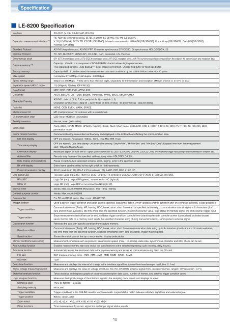
Specification<strong>LE</strong>-<strong>8200</strong> SpecificationInterfaceExpansion measurement interface. (*1)Standard ProtocolOptional ProtocolSynchronous clockCapture memory (*3)Backup memoryMax. speedSpeed setting rangeExpansion speed (HDLC mode)Data formatData codeCharacter FramingParity bitMultiprocessor bitBit transmission orderPolarity inversionError checkOnline monitor functionIdle time displayTime stamp displayLine status displayAddress filterData display and operationsBit shift displayProtocol translation displayLine status <strong>LE</strong>DRS-232COther I/FInterval timerGeneral-purpose counterData counterTrigger functionTrigger conditionTrigger actionData search functionSearch conditionSearch actionMonitor conditions auto settingAuto run/stop functionAuto save functionFile sizeMax filesDelay time functionSignal voltage measuring functionStatistical analysis functionLogic analyzer functionSampling clockSampling memoryTrigger conditionTrigger positionZoom in/outOther functionsRS-232C (V. 24), RS-422/485 (RS-530)RS-422/485 terminal block [<strong>LE</strong>-25TB], X. 20/21 [<strong>LE</strong>-25Y15], RS-449 [<strong>LE</strong>-25Y37],V. 35 [<strong>LE</strong>-25M34], 3V/5V TTL/I 2 C/SPI [OP-SB85], Infrared communication IrDA/ASK [OP-SB85IR], Current loop [OP-SB85C], CAN/LIN [OP-SB87],FlexRay [OP-SB88]ASYNC (Asynchronous), ASYNC-PPP, Character synchronous SYNC/BSC, Bit synchronous HDLC/SDLC/X. 25I 2 C, SPI, BURST (*2) , IrDA(IrLAP), CC-LINK, CAN, Devicenet, LIN, FlexRayST1 (DTE transmission clock), ST2 (DCE transmission clock), RT (DCE reception clock), AR (The synchronous clock extracted from the edge of the transmission and reception data)Capacity : 100MB It is composed of DDR-SDRAM of which allows high-speed access .Two separated screens. Auto backup (*4) . Error erasure prevention. Choose ring buffer or fixed size buffer.Capacity:4MB It can be saved the measurement data and conditions by the built-in lithium battery for 10 years.Full duplex: 2.150Mbps / Half duplex: 4.000Mbps50bps to 4.000Mbps Freely set to four effective digits, separately for transmission and reception. (Margin of error: 0. 01% or less)115.2Kbps to 12Mbps [OP-FW12G]NRZ, NRZI, FM0, FM1, 4PPM, ASKASCII, EBCDIC, JIS7, JIS8, Baudot, Transcode, IPARS, EBCD, EBCDIK, HEXASYNC : data bit (5, 6, 7, 8) + parity bit (0, 1) + stop bit (1, 2)Character synchronous : data bit + parity bit (6 or 8bits in total) Bit synchronous : data bit (8bits)NONE, ODD, EVEN, MARK, SPACEMP (multiprocessor) bit is shown with a special mark.LSB first or MSB first (switchable)Normal, Invert (switchable)Parity (ODD, EVEN, MARK, SPACE), Framing, Break, Abort, Short frame, BCC (LRC, CRC-6, CRC-12, CRC-16, CRC-ITU-T, FCS-16, FCS-32). BCCpermeation mode.Communication log is recorded continuously and displayed in the LCD without affecting the communication lines.OFF (no record); Resolusion: 100ms, 10ms, 1ms; Max 999. 9 secOFF (no record); Date time stamp: unit selectable among "Day/Hr/Min", "Hr/Min/Sec" and "Min/Sec/10ms"; Elapsed time from the measurementstart: 100µsec/10µsec/1µsecRecords and displays the wave form of 7 signals (chosen from RS(RTS), CS(CTS), ER(D<strong>TR</strong>), DR(DSR), CD(DCD), CI(RI), <strong>TR</strong>GIN(external trigger input) along with the transmission/ reception data.Records only frames of the specified address. (only when HDLC/SDLC/X.25)Pause in capture, two seperated screens, scroll, paging, jump to the specified screen.Entire frame can be shifted to the right or left in 1 bit increments.SDLC (modulo 8/128), ITU-T X.25 (modulo 8/128), LAPD, PPP, BSC, IrLAP, I 2 CTwo color <strong>LE</strong>Ds of SD, RD, RS(RTS), CS(CTS), ER(D<strong>TR</strong>), DR(DSR), CD(DCD), CI(RI), ST1(TXC1), ST2(TXC2), RT(RXC).Logic ON (red) , logic OFF (green) , no connection NC (light off)Logic ON (red) , logic OFF or no connection NC (light off)4kinds; Max. count: 999999 (Resolution: 1ms ,10ms ,100ms)4kinds; Max. count: 999999For SD and RD (1 each): Max. count: 4294967295Up to 8 pairs of trigger condition and action can be specified. (sequential action, which validates another condition after one condition satisfied, is also possible.)Communication error (Parity, MP, framing, BCC, break, abort, short frame can be specified individually.), communication data string up to 8 characters (don'tcare and bit mask available), idle time more than the specified duration, match time/counter value, logic status of interface signal line and extarnal trigger inputStops measurement/test (offset can be set), validates trigger condition: controls timer (start/stop/restart), controls counter (count/clear), activates buzzer,saves monitor data on a memory card, sends the specified character string (during manual simulation), sends pulse to external signalRetrieves the data with specific condition from capture memory.Communication error (Parity, MP, framing, BCC, break, abort, short frame),communication data string up to 8 characters (don't care and bit mask available),idle time more than the specified duration, specified timestamp (don't care available), trigger matching data.Shows the match data at the top or enumeration display (selectable)Measurement conditions such as protocol, transmission speed, (max. 115.2Kbps), data code, synchronous character and BCC check can be set.Enables measurement to start and end at the specified time at the selected repeating cycle (monthly, daily, hourly).Automatically saves the monitored data in the capture memory and saves as communications log file in the CF card.BUF (capture memory size) , 1MB , 2MB , 4MB , 8MB, 16MB , 32MB , 64MB1024Measures and displays the interval of change in the interface signal line. (current/min/max/average, resolution: 0. 1ms)Measures and displays the value of voltage amplitude: SD, RD, ER(D<strong>TR</strong>), external signal EXIN. (current/min/max, range 15V resolution : 0.1V)Takes statistics and displays graphs of transmission/reception data count, number of frames, and satisfied trigger condition count.Measures the logical change of the interface signal in the sampling clock period, and displays its wave.1KHz to 40MHz (15 steps)Min 4,000Trigger conditions in the ONLINE monitor functions match. Logical status match between interface signal line and external signal.Before, center, afterx10, x5, x2, x1, x1/2, x1/4, x1/8, x1/16, x1/32, x1/64Time measurement by cursor, signal line exchange, signal status search10