Redi-Rock Retaining Wall System (Final Report -- 2006)
Redi-Rock Retaining Wall System (Final Report -- 2006)
Redi-Rock Retaining Wall System (Final Report -- 2006)

You also want an ePaper? Increase the reach of your titles
YUMPU automatically turns print PDFs into web optimized ePapers that Google loves.
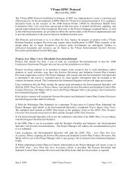
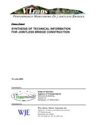
This report documents our observations during and post construction and provides asummary of our recommendations.Product DescriptionThe retaining wall system supplied by <strong>Redi</strong>-<strong>Rock</strong> TM International Inc was producedlocally through <strong>Redi</strong>-<strong>Rock</strong> TM <strong>Wall</strong>s of New England, a Carroll Company. The wallsystem achieves its structural integrity through the use of both its weight andnodules cast into the blocks as seen in Figure 1. The molds used during castingprovide the appearance of an aesthetic stone facing.Figure 1: Segmental piece of <strong>Redi</strong>-<strong>Rock</strong>wall illustrating the interlockingnodules cast into the blocks.<strong>Wall</strong> UnitsFor this project there were 4 different block types used. The type used was based onlocation, Top Blocks, Middle Blocks, Bottom Blocks or End Blocks. Figure 2shows the shop drawings illustrating the dimensions of the different block types.Figure 2: Typical block dimensions
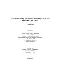
Leveling PadThe leveling pad is the base for the <strong>Redi</strong>-<strong>Rock</strong> TM retaining wall system. It needs to beconstructed of granular fill 12 inches thick and extending a minimum of 12 inchesbeyond either side of the base block.Design ConsiderationsThe height of the walls ranged from 3.0 to 7.5 feet high. Although not a tall wall, astandard cast in place concrete wall would have required an embedment of 4 feet for frostprotection. This would have required a substantially larger excavation and replacementof material than the 1 foot embedment required for the <strong>Redi</strong>-<strong>Rock</strong> TM wall. There was alsono field form work as would be necessary for a cast in place concrete wall allowing forconstruction during a broad range of weather conditions. The design required 2 feet ofGranular backfill for structures placed behind the wall to prevent the build up ofhydrostatic pressures and a geotextile fabric to separate the insitu soils from the granularbackfill. Geotextile was also placed directly behind the wall facing unit to allow fordrainage, but prevent erosion of the granular backfill.A subsurface investigation for the project should include an analysis on the frostsusceptibility of the insitu soil below the <strong>Redi</strong>-<strong>Rock</strong>TM retaining wall. If frostsusceptible materials are present it might be necessary to remove and replace the insitusoils with a granular borrow and drainage system.ConstructionThe <strong>Redi</strong>-<strong>Rock</strong> TM retaining wallsystem was assembled by the DonWeston Excavating Inc fromWilliston, Vermont. See Figure 3for Typical Cross-Section.The first stage of constructioninvolved placing the 12 inch thickgranular borrow layer. Thecontractor was originally going touse 12 inches of ¾” crushed stone,but it was found that it wasdifficult to get a slight batter onthe bottom row of blocks. Byusing 10 inches of the ¾” crushedstone beneath 2 inches of a 3/8”crushed stone the desired gradewas more readily achieved. Thisrecommendation was provided byFigure 3: Typical cross section of <strong>Redi</strong>-<strong>Rock</strong> TMretaining wall.
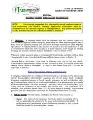
the manufacturer’s representative, but was not detailed in the plans.The plans called for a 15 foot radius curve in each of the <strong>Redi</strong>-<strong>Rock</strong> TM walls as shown in Figure4. It was found during installation that this could not be achieved for this location. Theinstallation plan was changed to have the walls turn at a 90 o angle, replacing the 15 foot radiuscurve. Figure 5 shows the walls as constructed.Figure 4: Proposed radius curveFigure 5: <strong>Retaining</strong> <strong>Wall</strong>s 1 and 2 constructed witha 90 o turn.During construction retaining wall #1 was extended approximately 80 feet to include an adjacentproperty (Figure 6) and a third <strong>Redi</strong>-<strong>Rock</strong> TM wall was added to the project. The additional wall isapproximately 60 feet in length and has a face area of 320 square feet. The contractor afterhaving installed the first 2 walls, found the third to proceed at a much faster pace. It onlyrequired 2 days to install the third <strong>Redi</strong>-<strong>Rock</strong> TM wall after having been through the learning curverequired to install the first 2 walls. The installed price for the third wall was approximately $30per square foot compared with approximately $33 per square foot for the first 2 walls. In thecontract the pay item for the wall was based upon a linear foot measurement. This method of
payment does not easily allow for payments due to field fit variations in wall design or changesin design. The pay item should be per square foot of wall face.ObservationsFigure 6: <strong>Retaining</strong> <strong>Wall</strong> 1 extended west to include adjacent property.• The original plans did not require or show underdrain below or behind the bottom rowof blocks. The resident engineer felt that this was an oversight and should have beenincluded. A drainage system was added to the project during construction.• On gradual curves there is enough “play” in the interlocking nodules such that the wallcan be constructed unimpeded. The nodules are on the tops of the blocks and thereceiving dimples on the bottom of the blocks are placed during the casting process.They appear to be placed assuming that the wall will be linear. When the wall isconstructed on a curve the nodules and dimples do not line up adequately causing thecontractor to saw cut some of the nodules. It would seem that this process would reducethe interlocking shear capacity of that wall section.• The wall system allowed for the easy addition of another row of blocks. One of theproperty owners was not satisfied with the original wall and requested that the wallheight be increased.• The Resident Engineer felt that the specifications did not provide enough detail withregards to quality control. The special provisions should be more specific in therequirements for acceptance of the modular blocks.
• The Contractor was pleased with the ease of installation of the wall system and stated thatthey would not hesitate to use this system on other projects.Recommendations• The specification should be written in such a manner as to allow the inspector moreauthority to reject blocks. Section 540 of the 2006 Vermont Standard Specifications forConstruction adds some of the needed requirements for the construction of this wallsystem, but it does not include tolerances for fabrication, damage that allows refusal of ablock, and construction tolerances.• There should be more details for drainage around the <strong>Redi</strong>-<strong>Rock</strong> TM <strong>Retaining</strong> walls.• The ability to construct a specific radius curvature needs to be investigated prior toincorporation into the plans.• The pay item for the wall was based upon a linear foot. This should be changed to asquare foot of wall face.The walls discussed in this report did not incorporate the use of geogrids as a stabilizing forcein the performance of the structure. The scope of this report is intended to only include the<strong>Redi</strong>-<strong>Rock</strong> TM wall system for structures 8 feet in height without geogrid reinforcements. In thefuture, the <strong>Redi</strong>-<strong>Rock</strong> TM retaining wall system will need to be designed on a project specificbasis due to the variability soil conditions and external loads acting on the retaining wall.In conclusion, it is recommended that the <strong>Redi</strong>-<strong>Rock</strong> TM retaining wall system be approved foruse on Agency projects and be added to the Vermont Agency of Transportation Earth<strong>Retaining</strong> <strong>System</strong> Selection Chart for walls 8 feet or less in height with a back slope up to 30 o .As the walls were constructed during the summer of 2006, we have not had the opportunity tomonitor the long term performance. It is also recommended that this project be monitored intothe future for any adverse changes and the changes be reported in future updates.