7188(D)/DOS Hardware Manual - ICP DAS USA
7188(D)/DOS Hardware Manual - ICP DAS USA
7188(D)/DOS Hardware Manual - ICP DAS USA

Create successful ePaper yourself
Turn your PDF publications into a flip-book with our unique Google optimized e-Paper software.
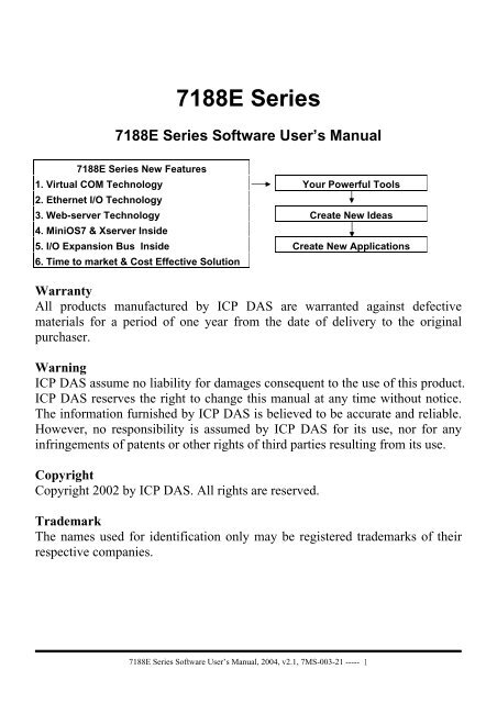
Table of Contents1. INTRODUCTION ..............................................................................................................................................................31.1 3 TYPICAL APPLICATIONS .............................................................................................................................................41.2 DIRECTORY TREE OF SOFTWARE AND LITERATURE ......................................................................................................81.3 SOFTWARE INSTALLATION.........................................................................................................................................101.4 SOFTWARE UTILITIES.................................................................................................................................................131.5 PC DIAGNOSTIC TOOLS..............................................................................................................................................172. MINIOS7 OF THE <strong>7188</strong>E SERIES.................................................................................................................................202.1 MINIOS7 FOR THE <strong>7188</strong>E SERIES...............................................................................................................................202.2 DEMO PROGRAMS FOR THE <strong>7188</strong>E SERIES .................................................................................................................233. VXCOMM APPLICATIONS..........................................................................................................................................243.1 OVERVIEW .................................................................................................................................................................243.2 INSTALLING THE VXCOMM DRIVER...........................................................................................................................273.3 ADDING A <strong>7188</strong>E/8000E SERVER AND CONFIGURING THE VXCOMM DRIVER............................................................293.4 REMOVING A <strong>7188</strong>E/8000E SERVER ..........................................................................................................................373.5 UNINSTALLING THE VXCOMM DRIVER......................................................................................................................393.6 DIAGNOSTICS AND TROUBLE SHOOTING....................................................................................................................403.7 FAQ...........................................................................................................................................................................524. ETHERNET I/O APPLICATIONS ................................................................................................................................534.1 OPERATION PRINCIPLE OF THE XSERVER ...................................................................................................................534.2 COMMAND PROTOCOL OF XSERVER ..........................................................................................................................544.3 DEMO PROGRAM LIST OF XSERVER ............................................................................................................................664.4 CLIENT PROGRAM LIST FOR XSERVER ........................................................................................................................694.5 PROGRAMMING OF XSERVER .....................................................................................................................................724.6 USING CLIENT PROGRAMS ..........................................................................................................................................794.7 DEMO PROGRAMS OF XSERVER .................................................................................................................................885. GLOSSARY ....................................................................................................................................................................102<strong>7188</strong>E Series Software User’s <strong>Manual</strong>, 2004, v2.1, 7MS-003-21 ----- 2
1. IntroductionOne <strong>7188</strong>E series controller comes equipped with one RJ-45 connector, oneI/O expansion bus and several serial COM ports. The <strong>7188</strong>E is an embeddedcontroller which, with aid of c language, can help you develop your ownprograms. Included with the <strong>7188</strong>E are many demos and libraries. The <strong>7188</strong>Ecan be used to access devices via Ethernet/Internet or RS-232/485/422. Inaddition, each <strong>7188</strong>E controller has one I/O expansion bus. Our expansionboards can be mounted quickly and easily to implement various I/Ofunctions,such as D/I, D/O, A/D, D/A, Timer/Counter, Flash memory andbattery backuped SRAM.<strong>7188</strong>E Series Software User’s <strong>Manual</strong>, 2004, v2.1, 7MS-003-21 ----- 3
1.1 3 typical applications<strong>7188</strong>E series controllers have 3 typical applications (Virtual COM, EthernetI/O and web server implementation). These applications use different firmwareand program styles. Users can choose any of the 3 applications they prefer.Using the Virtual COM application, one PC can control 256 COM ports(including real COM ports). The VxComm firmware will turn your <strong>7188</strong>E intoa RS-232 to Ethernet/Internet converter.Using the Ethernet I/O and Web Server applications, users can program thefirmware of the <strong>7188</strong>E (Xserver, Web server).ApplicationVxCommTCP/IPApplicationProgramBrowser( IE, Netscape)Rs-232TCP/UDPVirtual COMEthernet I/OWeb serverHub<strong>7188</strong>E seriesEthernetRS-232RS-485DeviceFirmwareVxcommXserverWeb serverI/O Expansion BusI/O expansionBoard<strong>7188</strong>E Series Software User’s <strong>Manual</strong>, 2004, v2.1, 7MS-003-21 ----- 4
1.1.1 Virtual COM applicationExpansion board of the<strong>7188</strong>E(IP-1) are mappedto COM3 of PC(1)COM1/COM2 of the<strong>7188</strong>E(IP-1) are mappedto COM4/COM5 ofPC(1)To use the Virtual COM application, first install the VxComm Driver. Afterinstallation, the VxComm Utility can map any <strong>7188</strong>E’s remote COM port.These virtualized COM ports can be used by the PC to control devices directly,just as you would use COM1 (real COM port) to control devices. When usingthe Virtual COM application, one PC can use a maximum of 256 COM ports.Users need not worry about network connections. The VxComm Driver willhandle all Ethernet/Internet connections.The advantages of VxComm:1. Users can upgrade their systems to the Ethernet/Internet with increased easeas program code needs no modification.2. The internal firmware of <strong>7188</strong>E supports multiple clients. One <strong>7188</strong>E canhandle a maximum of 30-N socket connections simultaneously, with Nbeing the number of the <strong>7188</strong>E’s COM ports.For example: If one PC uses two virtual COM ports connected to COMports of one <strong>7188</strong>E2, the <strong>7188</strong>E2 allows a maximun of 14 PC connections.<strong>7188</strong>E Series Software User’s <strong>Manual</strong>, 2004, v2.1, 7MS-003-21 ----- 5
1.1.2 Ethernet I/O applicationThe Xserver is a powerful program designed for Ethernet I/O applications. Itsupplies the <strong>7188</strong>E with a range of flexible options. Users can modify theXserver to control all of the <strong>7188</strong>E’s hardware: COM ports, I/O expansionboards, a 7 Seg LED, or other relevant products.The advantages of the Xserver:1. We design, maintain, update the Xserver for all users.2. Xserver can be easily modified through the use of general developmenttools such as TC/BC/MSC. All relative libraries are coded in C language.3. High running speed. The original Xserver (Demo4.exe) can run about 750scan loops per second (version 2.6.14).4. Most program code of the Xserver is finished. Ethernet/Internetcommunication and program loop control are all finished in VxComm.lib.<strong>7188</strong>E Series Software User’s <strong>Manual</strong>, 2004, v2.1, 7MS-003-21 ----- 6
This vastly reduces user’s developing time.5. To modify Xserver, users need only to modify the 6 functions6. The command protocol is designed to fit most of the <strong>7188</strong>E’s requirements.7. Users can develop and extend their private command protocol very easily.8. It supports multi-clients. The Xserver can handle a maximum of 30-Nconnections simultaneously, with N being the number of the <strong>7188</strong>E’s COMports.9. Auto wake up option. The Xserver will check on packet timeouts. If thesoftware crashes, the Xserver will wake itself up automatically.10. The Xserver demos (TC/BC/MSC) and Client demos (VB/VC) are included.1.1.3 Web server applicationWith the help of Web server, users are able to use standard browsers (such asIE or Netscape) to access the I/Os of the expansion boards or devicesconnected to any of the <strong>7188</strong>E’s COM port.<strong>7188</strong>E Series Software User’s <strong>Manual</strong>, 2004, v2.1, 7MS-003-21 ----- 7
1.2 Directory tree of software and literatureTo help users reduce developing time, we support many software resources,including documents, drivers, libraries, diagnostic programs, client programsand many Xserver demos. You can quickly find which resources you need byusing the directory tree.The content of shipped CD:AUTORUN.INF for CD auto runREADME.TXT please read this file firstNAP<strong>DOS</strong> Web Company web siteAr4 for Acrobat readerBin for autorun7000 README.TXT please read this file first7000Util Windows utility for 7000/8000NAP7000S <strong>DOS</strong> driver for 7000/8000NAP7000D DDE server for 7000/8000NAP7000X OCX library for 7000/8000NAP7000P DLL library for 7000/8000NAP7000OPCSvr OPC server for 7000/8000NAP7000V LabView driver for 7000/8000<strong>7188</strong>E Document User’s manuals and application notesMiniOS7 CPU and I/O libraries and demo programsTcp TCP libraries and demo programsUdp UDP libraries and demo programsNote: The software & manual are updated frequently, so the content of thecompanion CD is also updated frequently. The best way is to read everyREADME.TXT located in every directory. All updated information is given inthese files.<strong>7188</strong>E Series Software User’s <strong>Manual</strong>, 2004, v2.1, 7MS-003-21 ----- 8
Sub directory tree of <strong>7188</strong>E:<strong>7188</strong>EDocumentReadme.htmMiniOS7DemoDocBig5/Eng/Gb2312TCPPCDiagSetupSource1. Configure Wizard2. Send2323. Send TCP4. <strong>7188</strong>EVxCommDocBig5/Eng/Gb2312vxcomm.htmDriver(PC)NT/2K/XPServer(<strong>7188</strong>e)Web-ServerXserver<strong>7188</strong>EA/<strong>7188</strong>E2/.../<strong>7188</strong>E8ClientVB/VCDemoBC/MSC/TCDemoLibv7000Xserver.htmFunction.htmOtherUDPOther<strong>7188</strong>E Series Software User’s <strong>Manual</strong>, 2004, v2.1, 7MS-003-21 ----- 9
1.3 Software Installation1.3.1 Installation StepsThe installation steps are given as follows:Step 1: Change the directory to the destination folder as follows.For example (CD-ROM Drive is "D:")C:\>d:D:\>cd \NAP<strong>DOS</strong>\<strong>7188</strong>E\D:\NAP<strong>DOS</strong>\<strong>7188</strong>E\>_Step 2: Make a new directory for the <strong>7188</strong>E. Xcopy all files.C:\>md <strong>7188</strong>EC:\>cd <strong>7188</strong>EC:\<strong>7188</strong>E\>xcopy d: c: /s /v1.3.2 Installing <strong>7188</strong>X.exe/<strong>7188</strong>XW.exeThe <strong>7188</strong>X.exe/<strong>7188</strong>XW.exe is used to download and debug programs.Users should copy it to the PATH directory first. Then user can execute<strong>7188</strong>X.exe/<strong>7188</strong>XW.exe in any directory on the host-PC. The installation stepsare given as follow:Step 1: Change the directory to the destination folder as follows.For example (CD-ROM Drive is "D:")C:\>d:D:\>cd \NAP<strong>DOS</strong>\<strong>7188</strong>E\MiniOS7D:\NAP<strong>DOS</strong>\<strong>7188</strong>E\MiniOS7\>_Step 2: Copy <strong>7188</strong>X.EXE from CD to the PATH directory (defined in PATH).C:\>cd windowsC:\windows\>copy d:<strong>7188</strong>x.exeNote: <strong>7188</strong>XW.exe is designed for win32 system. So it can be used for USB-RS232 or PCMCIA-RS232 port.<strong>7188</strong>E Series Software User’s <strong>Manual</strong>, 2004, v2.1, 7MS-003-21 ----- 10
1.3.3 Installing PC diagnostic toolsStep1: Run Setup.exe from the <strong>7188</strong>e\TCP\PCDiag\Setup directory.Setp2: Choose destination folder.Step3: Select program folder.<strong>7188</strong>E Series Software User’s <strong>Manual</strong>, 2004, v2.1, 7MS-003-21 ----- 11
Step4: Start copying files.After finished installing, 5 items can be found in the PCDiag group.<strong>7188</strong>E Series Software User’s <strong>Manual</strong>, 2004, v2.1, 7MS-003-21 ----- 12
1.4 Software Utilities1.4.1 <strong>7188</strong>X.EXE Utility for Host-PCThe utility program, <strong>7188</strong>X.EXE, can be used as follows:• Downloads user’s programs from host-PC into <strong>7188</strong>, <strong>7188</strong>X, <strong>7188</strong>E and8000 families.• Shows debug string to monitor of host-PCThree standard output libraries, Putch, Print & Puts, will allow main controlunit to send output string to monitor of Host-PC.<strong>7188</strong>X/<strong>7188</strong>E/8000Main(){Print(“\nTest 123”);…………………}COM1RS-232115200, N81COM1/2Monitor of host-PCTest 123Host-PCRun <strong>7188</strong>X.EXE• Keys-in test data from keyboard of host-PCThree standard input libraries, Getch, Scanf & LineInput, will allow maincontrol unit to read keyboard from Host-PC.Monitor of host-PC<strong>7188</strong>X/<strong>7188</strong>E/8000Main(){float r;…………………Scanf(“\n%f”,&r);Print(“\nR=%f”,r);…………………}COM1RS-232115200, N81COM1/2R=3.14159Host-PCRun <strong>7188</strong>X.EXE3.14159Keyboard of host-PC<strong>7188</strong>E Series Software User’s <strong>Manual</strong>, 2004, v2.1, 7MS-003-21 ----- 13
Hot-key of <strong>7188</strong>x.exe:Command DescriptionF1 Shows help messages of <strong>7188</strong>x.exeAlt_1 Uses PC's COM1Alt_2 Uses PC's COM2Alt_C Switches to command mode to change PC COM port’s baudrateand data format.Press ENTER to confirm the setting.Press LEFT/RIGHT arrow key to select different field.Press Any key to switch different values.Press ENTER in the last field will stop this operation.Alt_D Sets the date of RTC to the PC's date.Alt_T Sets the time of RTC to the PC's timeAlt_E For downloading files into memory. Only after the message“Press ALT_E to download file!” is shown on screen, can userspress Alt_E.Alt_L Switches normal/line mode. In line-mode, all characters-pressedwill not send to COM until the ENTER is pressed. It is designedfor testing the 7000 series.Alt_X Quits <strong>7188</strong>X.EXE.F2 Sets the file name for download (without download operation).Alt_F2 Sets multiple filenames for download. (10 files maximum. If setless then 10 files, add '*' to end.)Ctrl_F2 Shows COM1 & COM2 messages (for easily COM port testing).Press ALT_X to return to the original mode.Press TAB to switch the cursor between these two windows.F5 Runs the program specified by F2 and arguments set by F6.F6 Sets the arguments of the execution file set by F2. (10 argumentsmaximum. If set less than 10 arguments, add ‘*’ to end).F8 F8=F9+F5.F9 Downloads the file specified by F2 into FLASH memory.Alt_F9 Downloads all files specified by ALT_F2 into FLASH memory.F10 Downloads the file specified by F2 into SRAM and execute it.F12 For 7521/7522/7523 to test RS-232.… more … … more …<strong>7188</strong>E Series Software User’s <strong>Manual</strong>, 2004, v2.1, 7MS-003-21 ----- 14
1.4.2 <strong>7188</strong>XW.EXE Utility for Host-PC<strong>7188</strong>xw.exe is the Win32 version of <strong>7188</strong>x.exe. The difference beteween<strong>7188</strong>x.exe and <strong>7188</strong>xw.exe is:<strong>7188</strong>x.exe: Uses standard COM ports (COM1/COM2).<strong>7188</strong>xw.exe: Supports RS-232 COM ports using USB and PCMCIA interfaces.Command line options of <strong>7188</strong>xw.exe:Option Description/c# Uses PC's COM#/b# Sets baudrate of PC’s COM port (default is 115200)/s# Sets screen’s display-rows (default is 25, max. is 50)Hot-key of <strong>7188</strong>xw.exe:Command DescriptionF1 Shows help messages of <strong>7188</strong>xw.exeAlt_F1 Shows the Chinese (Big5) help messages of <strong>7188</strong>xw.exeCtrl_F1 Shows the Chinese (GB2312) help messages of <strong>7188</strong>xw.exeAlt_1 Uses PC's COM1Alt_2 Uses PC's COM2Alt_3 Uses PC's COM3Alt_4 Uses PC's COM4Alt_5 Uses PC's COM5Alt_6 Uses PC's COM6Alt_7 Uses PC's COM7Alt_8 Uses PC's COM8Alt_9 Uses PC's COM9Alt_A Switches between normal mode and ANSI-Escape-code-supportmodeAlt_C Switchs to command mode. Supports commands:b#: sets new baudrate of PC’s COM ports.c#: Uses PC’s COM#.n/e/o: sets parity to none/even/odd.5/6/7/8: sets data bits to 5/6/7/8.p#: sets PC’s working directory.q: quits command mode.<strong>7188</strong>E Series Software User’s <strong>Manual</strong>, 2004, v2.1, 7MS-003-21 ----- 15
Alt_D Sets the date of RTC to the PC's date.Alt_T Sets the time of RTC to the PC's timeAlt_E For downloading files into memory. Only after the message“Press ALT_E to download file!” is shown on screen, can userspress Alt_E.Alt_H Switches Hex/ASCII display mode.Alt_L Switches normal/line mode. In line-mode, all characters-pressedwill not send to COM until the ENTER is pressed. It is designedfor testing the 7000 series.Alt_X Quits the <strong>7188</strong>X.EXE.F2 Sets the file name for download (without download operation).F5 Runs the program specified by F2 and arguments set by F6.Alt_F5 Runs the program stored in SRAM.F6 Sets the arguments of the execution file set by F2. (10 argumentsmaximum. If set less than 10 arguments, add ‘*’ to end).Ctrl_F6 Clears screen.F8 F8=F9+F5.F9 Downloads the file specified by F2 into FLASH memory.Alt_F9 Downloads all files specified by ALT_F2 into FLASH memory.F10 Downloads the file specified by F2 into SRAM and execute it.Alt_F10 Downloads the file specified by F2 into SRAM memory.Ctrl_B Sends a BREAK signal to the PC’s COM port that is used by<strong>7188</strong>xw.exe.… more … … more …<strong>7188</strong>E Series Software User’s <strong>Manual</strong>, 2004, v2.1, 7MS-003-21 ----- 16
1.5 PC Diagnostic toolsThe PC Diagnostic tools include:‣ Configure Wizard: guides users step by step in configuring the<strong>7188</strong>E/8000E’s network setting.Please refer to sec. 3.3 of “<strong>7188</strong>E Series <strong>Hardware</strong> user’s manual” for moreoperating details.<strong>7188</strong>E Series Software User’s <strong>Manual</strong>, 2004, v2.1, 7MS-003-21 ----- 17
‣ Send232: uses serial port (RS-232) interface to communicate with devices.Can be used to test the Virtual COM technology.Please refer to sec. 3.6 for more operating details.‣ SendTCP: uses TCP protocol to communicate with the <strong>7188</strong>E/8000E anddevices which are connected to the <strong>7188</strong>E/8000E’s COM ports.Please refer to sec. 4.6 for more operating details.<strong>7188</strong>E Series Software User’s <strong>Manual</strong>, 2004, v2.1, 7MS-003-21 ----- 18
‣ <strong>7188</strong>e: Command-prompt mode program, used to send data to specificmachines using TCP protocol.Usage:<strong>7188</strong>e [-S:IP] [-P:Port] Connect to a device by using TCP protocol.*Q Quit program and disconnect.Commands<strong>7188</strong>E Series Software User’s <strong>Manual</strong>, 2004, v2.1, 7MS-003-21 ----- 19
2. MiniOS7 of the <strong>7188</strong>E Series2.1 MiniOS7 for the <strong>7188</strong>E SeriesThe MiniOS7 is an embedded O.S. designed for the following families:• <strong>7188</strong>XA/<strong>7188</strong>XB/<strong>7188</strong>XC series• 7521/7522/7523 series• <strong>7188</strong>EA/<strong>7188</strong>EX/<strong>7188</strong>EX-256 series• <strong>7188</strong>E1/<strong>7188</strong>E2/<strong>7188</strong>E3/<strong>7188</strong>E4/<strong>7188</strong>E5/<strong>7188</strong>E8 series• 8000 series.• Iview-100 series• More new embedded controller families•It is used to replace the ROM<strong>DOS</strong> used in the <strong>7188</strong> series. Several brandsof <strong>DOS</strong> have been created by various companies. In all cases, <strong>DOS</strong>, whetherPC-<strong>DOS</strong>, MS-<strong>DOS</strong>, or ROM-<strong>DOS</strong>, is a set of commands or code which tellsthe computer how to process information. <strong>DOS</strong> runs programs, manages files,controls information processing, directs input and output, and performs manyother related functions. The MiniOS7 provides equivalent functions ofROM<strong>DOS</strong> and provides more specfic functions for the <strong>7188</strong>X/7521/8000family.Comparison between MiniOS7 and ROM-<strong>DOS</strong>:FunctionMiniOs7 RomDosPower up time 0.1 sec 4 ~ 5 secSupports I/O expansion bus Yes NoSupports AsicKey Yes NoSupports hardware unique serial number Yes NoSupports MMI, Iview-100 series Yes NoSupports Ethernet 10M interface, <strong>7188</strong>E & 8X3X series Yes NoDirectly downloads executable programs into Flash ROM Yes NoO.S. updateable (downloadable) Yes NoBuilt-in hardware diagnostic functions Yes NoDirectly controls 7000 series modules Yes NoCustomers ODM functions Yes NoFree of charge Yes No<strong>7188</strong>E Series Software User’s <strong>Manual</strong>, 2004, v2.1, 7MS-003-21 ----- 20
Note: We reserve the right to change the specifications of MiniOS7 withoutnotice.Command Set of MiniOS7:Command DescriptionLED5 pos value Shows a HEX value in the specified position of 5-digit LED.USE NVRAM Into the service routine for read/write NVARM.USE EEPROM Into the service routine of read/write EEPROM.USE Flash Into the service routine of read/write Flash-ROM.USE COM2 /option Into the service routine of send/receive to/from COM2 (RS-485).DATESets the date of RTC.[mm/dd/yyyy]TIME [hh:mm:ss] Sets the time of RTC.MCBTests current memory block.UPLOAD The first step to update the MiniOs7.BIOS1The last step to update the MiniOs7.LOADDOWNLOADs the user program into the Flash-Memory.DIR [/crc] Shows the information of all files download in the Flash-Memory.RUN [fileno] Runs the file with file-number=fileno, no filenethe last file.NameRuns the file with file-name=name.DELETE (or DEL) Deletes all files stored in the Flash-Memory. It will delete all files.RESETResets the CPU.DIAG [option] <strong>Hardware</strong> Diagnostic.BAUD baudrate Sets the new value of communication-baudrate to baudrate.TYPE filename [/b] Lists content of the file.REP [/#] command Repeats executing the same command # times.RESERVE [n] Reserves n Flash Memory sectors for USER's programs.LOADRDownloads a file into SRAM.RUNR [param1[param2...]]Runs a program saved into SRAM (downloaded by commandLOADR).I/INP/IW/INPW port Reads data from the hardware PORT.O/OUTP/OW/OUTP Outputs to hardware PORT.W port value… more … … more …*** Refer to <strong>7188</strong>E\MiniOS7\DOC\Index.htm for user’s manual & demoprograms for the MiniOS7 ***<strong>7188</strong>E Series Software User’s <strong>Manual</strong>, 2004, v2.1, 7MS-003-21 ----- 21
There are some of the libraries included with the <strong>7188</strong>E.<strong>7188</strong>EL.LIB: CPU & I/O related library (Large model)TCPIPL.LIB: TCP/IP related library (Large model)VComNNNN.LIB: Xserver related library (Large model), with NNNN beingthe version of library.Some of the libraries supported by <strong>7188</strong>E.LIB are given as follows:Function ExampledescriptionCOM port InstallCom1, InstallCom2, ……, InstallCom5, InstallCom36,InstallCom47, InstallCom58IsCom1, IsCom2,………………, IsCom7, IsCom8ToCom1, ToCom2, ……, ToCom7, ToCom8ReadCom1, ReadCom2, ………, ReadCom7, ReadCom8EEPROM WriteEEP, ReadEEP, EnableEEP, ProtectEEPNVRAM & ReadNVRAM, WriteNVRAM, GetTime, SetTime, GetDate,RTC SetDateLED & LedOn, LedOff, LedToggle, Init5DgitLed, Show5DigitLed,5DigitLed Show5DigitLedWithDotFlash Memory FlashReadId, FlashErase, FlashRead, FlashWriteTimer & TimerOpen, TimerClose, TimerResetValue, TimerReadValueWatchdog StopWatchReset, StopWatchRead, StopWatchStopTimer InstallUserTimer EnableWDT, DisableWDT, RefreshWDTFile GeFileNo, GetFileName, GetFilePositionByNo,GetFilePositionByNameConnects to SendCmdTo7000, ReceiveResponseFrom70007000Programmable SetDio4Dir, SetDio4High, SetDio4Low, GetDio4I/OOthers Kbhit, Getch, Putch, LineInput, ScanfRefer to <strong>7188</strong>e\document\TCPIPLib.pdf &<strong>7188</strong>e\minios7\doc\index.htm &<strong>7188</strong>e\document\WebLib.pdf for more information.Refer to <strong>7188</strong>e\document\TCPIPLib.pdf for how to compile & link.<strong>7188</strong>E Series Software User’s <strong>Manual</strong>, 2004, v2.1, 7MS-003-21 ----- 22
2.2 Demo Programs for the <strong>7188</strong>E SeriesWe provide hundreds of demo programs for users. The source codes are all inthe shipped CD. It is recommended to edit & modify these demo programswhen starting user’s special applications. The demo programs can be classed asfollows:Some of the demo programs designed for MiniOS7 are given as follows:Demo DescriptionHello Can run on PC or 8000, just use Print() to print:"*** Hello 8000 ***"Hello1 Demo for using functions: Is8000, GetLibVersion, PrintHello2 Demo for using C++ compiler.FILE Demo information in obtaining file information and file positionin Flash memory. All file data is stored in Flash Memory.In MiniOS7, cannot use C's functions: fopen, fclose, fread,fwrite.BATCH An example of BATCH files (*.BAT).SCANF Demo for using LineInput and Scanf.RUNPROG Uses Ungetch to send commands to MiniOS7 to run anotherprogramDEMO90-98 Demos for using TIMER functions.Location: <strong>7188</strong>e\MiniOS7\Demo\*.*Some typical TCP/IP demo programs are given as follows:Typical TCP/IP demo <strong>7188</strong>E PCPing demo Client, ping.exe NoneTelnet server demo Server, telserv.exe Client, telnet.exeTelnet server demo2Server, telserv2.exe Client, telnet.exeDemo1: TCP/IP demo Server, demo1.exe Client, Client1.exeDemo2: TCP/IP demo Server, demo2.exe Client, Client1.exeDemo3: TCP/IP demo Server, demo3.exe Client, Client1.exeLocation: <strong>7188</strong>e\TCP\Other\*.*Refer to Sec. 4.7 for more TCP/IP demo program designed for Xserver.Refer to <strong>7188</strong>e\document\TCPIPLib.pdf,<strong>7188</strong>e\minios7\doc\index.htm and<strong>7188</strong>e\document\WebLib.pdf for more information.Refer to sec. 5.2 for how to compile and link.<strong>7188</strong>E Series Software User’s <strong>Manual</strong>, 2004, v2.1, 7MS-003-21 ----- 23
3. VxComm Applications• Overview• Installing the VxComm Driver• Adding a <strong>7188</strong>E/8000E server and configuring the VxComm Driver• Removing a <strong>7188</strong>E/8000E server• Uninstalling the VxComm Driver• Diagnostics and Trouble Shooting• FAQ3.1 OverviewThe VxComm (Virtual Comm) Driver and VxComm Utility are very easyto install and use. The first thing to do is to find the installation file in theincluded CD. The directory is:‣ <strong>7188</strong>e\TCP\VxComm\NT\VxCommNT.exe(for Windows NT 4.0) or‣ <strong>7188</strong>e\TCP\VxComm\2K\VxComm2K.exe(for Windows 2000, Windows XP).This document shows how to install and configure the driver correctly.There are three parts to the quick start manual. The first part instructs usershow to install the software. The second part shows how to add a <strong>7188</strong>E/8000Eserver and configure a COM port. Finally, the third part teaches you how toremove a <strong>7188</strong>E/8000E server.<strong>7188</strong>E Series Software User’s <strong>Manual</strong>, 2004, v2.1, 7MS-003-21 ----- 24
3.1.1 ArchitectureThe VxComm Driver creates COM port(s) and maps them to the COMport(s) of the <strong>7188</strong>E/8000E. The user's RS-232 client programs need only tochange to the different COM port to access the serial devices that are allocatedto the Internet or Ethernet network via the <strong>7188</strong>E/8000E.<strong>7188</strong>E Series Software User’s <strong>Manual</strong>, 2004, v2.1, 7MS-003-21 ----- 25
3.1.2 Ports mappingVxcomm Driver/Utility supports Port 1 to Port 8 in accessing COM1 toCOM8 of the <strong>7188</strong>E/8000E. Another Port I/O is designed to access the I/Oboards mounted on <strong>7188</strong>E or 8000E.With the help of the VxComm Driver/Utility, uses can map remote COM portand I/O boards to become a virtual COM port of PC. One PC can control amaximun of 256 COM ports (including COM1 and COM2).Local COM Port(PC)VxComm Driver/Utility(PC)COM ? Port 1 COM1COM ? Port 2 COM2COM ? Port 3 COM3COM ? Port 4 COM4COM ? Port 5 COM5COM ? Port 6 COM6COM ? Port 7 COM7COM ? Port 8 COM8COM ? Port I/O I/O boardRemote COM port(<strong>7188</strong>E/8000E)<strong>7188</strong>E Series Software User’s <strong>Manual</strong>, 2004, v2.1, 7MS-003-21 ----- 26
3.2 Installing the VxComm DriverStep 1: Run VxComm2K.exe (for Windows2000, Windows XP) orVxCommNT.exe (WindowsNT4.0) or VxComm98.exe from the\Napdos\<strong>7188</strong>e\Tcp\VxComm\driver (pc)\2k or NT or 9x directory.Step2: Choose a destination folder.Step 3: Choose a program folder.<strong>7188</strong>E Series Software User’s <strong>Manual</strong>, 2004, v2.1, 7MS-003-21 ----- 27
Step 4: Select the "Yes, ... " option and click the "Finish" button to reboot yourcomputer.Step 5: After rebooting the computer, the VxComm Utility will ask you toconfigure the virtual COM port(s). Please refer to the next section formore information.Note:The Vxcomm driver is located on <strong>7188</strong>e\Tcp\VxComm\driver (pc)<strong>7188</strong>E Series Software User’s <strong>Manual</strong>, 2004, v2.1, 7MS-003-21 ----- 28
3.3 Adding a <strong>7188</strong>E/8000E server andconfiguring the VxComm Driver<strong>7188</strong>E/8000E's default IP address is 192.168.255.1.Step1: Obtain the IP address of the <strong>7188</strong>E/8000E. Either <strong>7188</strong>x.exe,<strong>7188</strong>xw.exe or Configure wizard can help you in obtaining the IPaddress of the <strong>7188</strong>E/8000E. Refer to Sec. 3 of “<strong>7188</strong>E hardware user’smanual” for information regarding the use of these three tools.Step 2: Select the "VxComm Utility".<strong>7188</strong>E Series Software User’s <strong>Manual</strong>, 2004, v2.1, 7MS-003-21 ----- 29
Step 3: Enter the IP address of the <strong>7188</strong>E/8000E server and press the "AddServer" Button.Note:"Check Duplicate" option:Enable this option to check whether the IP address is already listed in theserver window (left-hand window). Default is automatically checked. Thefollowing window pops up if IP address is duplicated."Check Server" option:Enable this option to connect to the <strong>7188</strong>E/8000E and get the device's namebefore adding to the server window (left-hand window). Default isautomatically checked. The following window pops up if host/server fails toconnect.<strong>7188</strong>E Series Software User’s <strong>Manual</strong>, 2004, v2.1, 7MS-003-21 ----- 30
"Timeout (ms)" field:This timeout value is used for Connecting, disconnecting andsending/receiving data in the VxComm Utility, and is used for Connectingand Disconnecting in the VxComm Driver."Command Port" field:By default, the Command/Configuration TCP port is 10,000. If you changethe setting of <strong>7188</strong>E/8000E, then you must assign the correct one in this fieldto let the VxComm Utility and Driver to get access to the device.Step 4: The following window pops up if you uncheck the "Check Server"option before pressing the "Add Server" button. Please choose a suitable"Model Number" of <strong>7188</strong>E/8000E and then click the "OK" button.Step 5: Select one of the <strong>7188</strong>E/8000E devices and configure the virtual COMport(s) by double clicking "Port1" or "Port2". (Port7000 is reserved.)<strong>7188</strong>E Series Software User’s <strong>Manual</strong>, 2004, v2.1, 7MS-003-21 ----- 31
Another example when adding the 8430 at IP address 10.10.34.12.Step 6: Select an appropriate COM port number, and then click the "OK"<strong>7188</strong>E Series Software User’s <strong>Manual</strong>, 2004, v2.1, 7MS-003-21 ----- 32
utton.Note:"Assign following COM number sequentially" option:This option will assign the following ports with the available COM portnumber sequentially and automatically.For example: If Port1 = COM4, then Port2 = COM5, Port3 = COM6"Use <strong>7188</strong>E/8000E current setting (Fixed Config)" option:You can click the "Port Configuration" button to configure this port's Baudrate and Data format settings. After the configuration, you can then checkthis option.Fixed Configuration (Use <strong>7188</strong>E/8000E's current setting):By using this feature, the VxComm Driver would not change the<strong>7188</strong>E/8000E's settings dynamically. This is proper when you have multiclientsto access the same <strong>7188</strong>E/8000E server.Dynamic Configuration (This's the default method):The VxComm Driver always change the <strong>7188</strong>E/8000E's settingsdynamically. It is proper for working with several different baud rate anddata format.For example, you may need to use 7000 Utility to make a search withseveral baud rates on the RS-485 network.Please also refer to "Configuring COM port of the <strong>7188</strong>E/8000E server".Step 7: Select one of the <strong>7188</strong>E/8000E devices and then click the "ServerOptions" button to configure the options.(Note: VxComm Utility 98 does not support the "Server Options" function yet!)<strong>7188</strong>E Series Software User’s <strong>Manual</strong>, 2004, v2.1, 7MS-003-21 ----- 33
Another example shown as follow: The port1 of 8430 map to COM20.<strong>7188</strong>E Series Software User’s <strong>Manual</strong>, 2004, v2.1, 7MS-003-21 ----- 34
Step 8: Key in the value and then click the "OK" button to exit.Notes:Keep Alive Time (ms) field:After connecting to the <strong>7188</strong>E/8000E, the VxComm Driver willautomatically and periodically send commands to keep the <strong>7188</strong>E/8000Ealive. The timer will be reset after each send/receive command/data success.The Keep-Alive mechanism won't work until the next timeout.The default setting of Keep-Alive time is about 7000 ms. It's recommendedsetting is (<strong>7188</strong>E/8000E's System Timeout * 1 / 3) or smaller value.Connection-Broken (ms) field:The VxComm Driver will try to re-connect if the connection is broken.When the client is sending a message to the <strong>7188</strong>E/8000E, the internet(TCP/IP) layer may respond with a "Disconnect" event to the VxCommDriver if it fails to send the message after 20 seconds or more. Users can seta smaller Connection-Broken time [for example : 10000 ms( 10 seconds)]to force the VxComm Driver to re-connect again and get a quicker response.If the connection has no sending/receiving signal before the Connection-Broken time has timed out, the connection will be marked as broken. TheVxComm Driver will also re-connect it again. Thus, the Keep-Alive Timeshould be smaller than the Connection-Broken time to make the connectioncome on-line.(Note: VxComm Driver 98 does not support the auto-reconnectionmechanism yet! )The default System Timeout (/STxxx) value of the <strong>7188</strong>E/8000E is about300 seconds. After client programs have connected to the <strong>7188</strong>E/8000E,clients have to send command to keep the <strong>7188</strong>E/8000E alive before ittimes out, otherwise the <strong>7188</strong>E/8000E will reset itself and clients will have<strong>7188</strong>E Series Software User’s <strong>Manual</strong>, 2004, v2.1, 7MS-003-21 ----- 35
to reconnect to the <strong>7188</strong>E/8000E again.Users can set the Keep-Alive Time and Connection-Broken time to 0 todisable this mechanism. The System Timeout will have to be set to 0 todisable the reset mechanism.Connect Timeout (ms) field:The timeout value will be passed into MS TCP/IP driver for reference whenconnecting and disconnecting.Command TCP Port field:By default setting, the <strong>7188</strong>E/8000E use TCP port 10000 as the Command /Configuration port. If you change the <strong>7188</strong>E/8000E's setting, you mustassign the correct one in the field. So the VxComm Driver can connect tothe right TCP port.This TCP port is used to configure the Baud rate, data format, CTS/RTScontrol mode and Break, etc.Port7000 Port field:By default setting, the <strong>7188</strong>E/8000E use TCP port 9999 as the Port7000port. This TCP port is reserved.Step9: Press the ‘Exit”button to save the settings and exit the VxCommUtility.<strong>7188</strong>E Series Software User’s <strong>Manual</strong>, 2004, v2.1, 7MS-003-21 ----- 36
3.4 Removing a <strong>7188</strong>E/8000E serverStep 1: Select the "VxComm Utility".Step 2: Click the server name you want to remove and press the "RemoveServer" button.<strong>7188</strong>E Series Software User’s <strong>Manual</strong>, 2004, v2.1, 7MS-003-21 ----- 37
Step 3: The following window will pop up, please make sure of your choiceand press the "Yes" button to remove it.Step 4: Press the "OK" button to finish this utility.<strong>7188</strong>E Series Software User’s <strong>Manual</strong>, 2004, v2.1, 7MS-003-21 ----- 38
3.5 Uninstalling the VxComm DriverStep 1: Select the "UnInstall VxComm".Step 2: Click the "Yes" button.Step 3: Click the "OK" button.<strong>7188</strong>E Series Software User’s <strong>Manual</strong>, 2004, v2.1, 7MS-003-21 ----- 39
3.6 Diagnostics and Trouble Shooting3.6.1 DiagnosticsAfter configuring the VxComm Driver by using the VxComm Utility, theVxComm Driver should work without error. However, users can use a simpletest to make sure it's working properly.Note: The test method depends on the user's devices and client programs.• Example 1: Loop-Back TestingStep 1: Make sure the VxComm Server is working in /m0 mode.(Please refer to sec. 4.2.3 “Options of command line”)Step 2: Wire the TXD1 with the RXD1 (COM1) of the <strong>7188</strong>E/8000E.<strong>7188</strong>E Series Software User’s <strong>Manual</strong>, 2004, v2.1, 7MS-003-21 ----- 40
Step 3: Virtualize <strong>7188</strong>E/8000E’s COM1 to become PC’s COM4 by using theVxComm Utility.Step 4: Run the <strong>7188</strong>xw.exe from the "Start / Run..." menu.Step 5: Press the + keys to use PC’s COM4.It will show "{*** Change to use COM4 ***}" message after changed.<strong>7188</strong>E Series Software User’s <strong>Manual</strong>, 2004, v2.1, 7MS-003-21 ----- 41
Step 6: Type some characters in the <strong>7188</strong>xw.exe window.The characters will be sent from PC’s COM4 to <strong>7188</strong>E/8000E’s COM1(through Path1), and immediately returned from the <strong>7188</strong>E/8000E’sCOM1 to the PC’s COM4 (through Path2) then shown on the PC’sminitor.• Example 2: Close-Loop TestingStep 1: Make sure the VxComm Server is working in /m0 mode.(Please refer to sec. 4.2.3 “Options of command line”)<strong>7188</strong>E Series Software User’s <strong>Manual</strong>, 2004, v2.1, 7MS-003-21 ----- 42
Step 2: Build connection as follows:Step 3: Run Send232 and then open PC’s COM1.<strong>7188</strong>E Series Software User’s <strong>Manual</strong>, 2004, v2.1, 7MS-003-21 ----- 43
Step 4: Virtualize <strong>7188</strong>E/8000E’s COM1 to become PC’s COM4 by using theVxComm Utility.Step 5: Run another Send232 and open PC’s virtual COM4.Step 6: Type “COM1” in left hand window, and press “Send”.Data will be sent from PC’s COM1 through Path1 to <strong>7188</strong>E/8000E’sCOM1 and immediately returned through Path2 to PC’s COM4.6.16.26.3Step 7: Type “Virtual COM” in right hand window, and press “Send”.Data will be sent from PC’s COM4 through Path2 to <strong>7188</strong>E/8000E’sCOM1 and immediately returned through Path1 to PC’s COM1.<strong>7188</strong>E Series Software User’s <strong>Manual</strong>, 2004, v2.1, 7MS-003-21 ----- 44
7.17.3 7.2Example 3: External-Devices TestingConnect 7000 series modules to <strong>7188</strong>E/8000E’s COM1. Use VxComm Driverto virtualize the <strong>7188</strong>E/8000E's COM1 to become PC’s COM10. Thus, we canuse the 7000 Utility to search the 7000 series module through COM10.Note: Users must install the 7000 Utility first by runingCD-ROM Drive:\Napdos\7000\7000Util\setup.exeStep 1: Run the 7000 Utility.<strong>7188</strong>E Series Software User’s <strong>Manual</strong>, 2004, v2.1, 7MS-003-21 ----- 45
Step 2: Build connection as follows:<strong>7188</strong>E Series Software User’s <strong>Manual</strong>, 2004, v2.1, 7MS-003-21 ----- 46
Step 3: Click the menu item "COM Port" to choose the COM port number,baudrate, and checksum. For example: COM10, 115200, 19200, 9600and No-Checksum. (These settings depend on the 7000 seriesmodule's settings.)<strong>7188</strong>E Series Software User’s <strong>Manual</strong>, 2004, v2.1, 7MS-003-21 ----- 47
Step 4: Click thesearch icon.Step 5: If the VxComm Driver works well, the 7000 Utility can search themodule(s) connected to the <strong>7188</strong>E/8000E’s COM1.3.6.2 Trouble ShootingProblem: Client program fail to open the COM port that was created by theVxComm Driver.Check:<strong>7188</strong>E/8000E's Power supply, Network cable, IP address, subnet-mask andgateway. (Please refer to the <strong>7188</strong>E/8000E user's manual for moreinformation.)<strong>7188</strong>E Series Software User’s <strong>Manual</strong>, 2004, v2.1, 7MS-003-21 ----- 48
Problem: Client program still fails to open the COM port.Check:Step 1: Right click the "My computer" icon and select the "Manage" option.1Step 2: Select the "Device Manager" icon from the "ComputerManagement" program.32Step 3: Click the menu item "View / Show hidden devices".<strong>7188</strong>E Series Software User’s <strong>Manual</strong>, 2004, v2.1, 7MS-003-21 ----- 49
Step 4: Select the item "Non-Plug and Play Drivers / Ynsernet".4.14.2Step 5: Right click the mouse button on the "Ynsernet" item and select the"Properties" menu item.5<strong>7188</strong>E Series Software User’s <strong>Manual</strong>, 2004, v2.1, 7MS-003-21 ----- 50
Step 6: Check if it shows the message "This device is working properly."If the driver does not work properly, please remove it and thenre-install and configure it again.Problem: Client programs open the COM port with success, but fail to accessthe device.Check:Check the device's power supply and wiring (RS-232: RXD, TXD; RS-485:D+, D- ; GND).<strong>7188</strong>E Series Software User’s <strong>Manual</strong>, 2004, v2.1, 7MS-003-21 ----- 51
3.7 FAQQ: Which modules are supported by VxComm Driver(PC) ?A: <strong>7188</strong>EA, <strong>7188</strong>EX, <strong>7188</strong>E1 ~ <strong>7188</strong>E8, 8430, 8431, 8830 and 8831(afterversion 2.0.0 Beta 6).Q: VxComm Driver(PC) v2.00 does not work with VxComm Server(<strong>7188</strong>E/8000E) v2.6.00 ?A: Yes, please upgrade the VxComm Server to version 2.6.14 or later version.The VxComm Server(<strong>7188</strong>E/8000E) v2.6.00 uses the "06" and "07"command to change the baudrate and the data format and then savesthese configurations into the EEPROM. The newer version adds the "02"and "03" command to change the baudrate and data format withoutsaving. These two commands improve the performance when changingbaudrate and data format. The VxComm Driver(PC) also changes theoperation when using the "02" and "03" commands. Thus, users have toupgrade their VxComm Server(<strong>7188</strong>E/8000E) to the later version.Q: Does the VxComm Driver (PC) support auto-reconnection after fixing anetwork break?A: Yes, the VxComm Driver (PC) supports the auto-reconnection mechanismafter version 2.00.The VxComm Utility allows users to set the server-options that includeKeep-Alive Time (ms) and Connection-Broken time (ms). Please refer tothe section: Adding a <strong>7188</strong>E/8000E server and configuring the VxCommdriver.<strong>7188</strong>E Series Software User’s <strong>Manual</strong>, 2004, v2.1, 7MS-003-21 ----- 52
4. Ethernet I/O Applications4.1 Operation Principle of the XserverThe typical TCP/IP mechanism is a standard tool but very complicated fora software engineer. It takes long time for a software engineer to develop aprograms using TCP/IP protocol.The command protocol designed for a TCP/IP system can be based onuser’s applications without any limitations. So every software engineer candesign his special protocol without any pre-defined standard. This will causesome of the troubles given as follows:• Is this protocol reliable?• Does this protocol fit all requirements?• How to maintain protocol created by another software engineer?• Time to market?• Engineering cost to design & debug this protocol?The Xserver is designed to solve all problems mentioned above as follows:‣ We design & maintain the reliable, original Xserver for all users.‣ The protocol is designed to fit all requirements of the <strong>7188</strong>E series.‣ The protocol is OPEN & expandable to reduce user’s design cost.‣ An easy-use interface is designed for user’s special applications.‣ Standard design and maintaince for all engineers using this protocol.The features of the Xserver are given as follows:‣ The Xserver, VComNNNN.EXE, is an embedded firmware designed forthe <strong>7188</strong>E series in the default shipping‣ Supports Virtual COM applications‣ Supports Ethernet I/O applications‣ Supports I/O expansion bus‣ Supports <strong>7188</strong>E1/2/3/4/5/8, <strong>7188</strong>EX & <strong>7188</strong>EA and etc.‣ TCP/IP protocol & command protocol is open & expandable.‣ Provides easy-use interface for user’s special programs.With the help of Xserver, a software engineer can design a robust Xserverin one day. We will provide about 50 ~ 100 typical real world applications foruser’s reference. From these demos, a software engineer can start easily with acost-friendly time to market. Refer to Sec. 4.3 for more information.<strong>7188</strong>E Series Software User’s <strong>Manual</strong>, 2004, v2.1, 7MS-003-21 ----- 53
4.2 Command Protocol of Xserver4.2.1 IP and port configurationBefore developing Ethernet I/O applications for your PC, you must first knowthe IP address and the Ethernet port number. The <strong>7188</strong>E/8000E and all COMports of the <strong>7188</strong>E/8000E use the same IP address, but different Ethernet portnumber. They are listed below:Function IP address Port numberModbus TCP 192.168.255.1 502Virtual 7000192.168.255.1 9999(I/O boards)<strong>7188</strong>E/8000E configuration 192.168.255.1 10000COM1 of the <strong>7188</strong>E/8000E 192.168.255.1 10001COM2 of the <strong>7188</strong>E 192.168.255.1 10002COM3 of the <strong>7188</strong>E/8000E 192.168.255.1 10003COM4 of the <strong>7188</strong>E/8000E 192.168.255.1 10004COM5 of the <strong>7188</strong>E 192.168.255.1 10005COM6 of the <strong>7188</strong>E 192.168.255.1 10006COM7 of the <strong>7188</strong>E 192.168.255.1 10007COM8 of the <strong>7188</strong>E 192.168.255.1 10008192.168.255.1 is the default IP address of the <strong>7188</strong>E/8000E. You can changethe IP address to suit your requirements. Contrary to the IP address, theEthernet port is fixed. You must use the port number as defined above.4.2.2 Command set of the XserverCmd ExplainInstruction FormatExample: Example:Sends to Xserver Receives from Xserver01 Version 01 V2.6.14[10/04/2001]02Sets baudrate(Doesn’t store the 02138400 OKsetting to EEPROM)03Sets data format(doesn’t store thesetting to EEPROM) 0328N1 OK04Gets system resetstatus 0414141(First asking from client)14 after system reset)140(Not first asking fromclient 14 after system reset)<strong>7188</strong>E Series Software User’s <strong>Manual</strong>, 2004, v2.1, 7MS-003-21 ----- 54
05 RTS0607Sets baudrate(Stores the setting toEEPROM)Sets data format(Stores the setting toEEPROM)1:On 0:Off0511 OK(COM Port RTS on) 06138400 OK
2627Sets the systemparameterSends Break signal toCOM Port of<strong>7188</strong>E/8000Eof <strong>7188</strong>Em='M': set the work option /M (n:0n:1)m='B': Set the Broadcast mode.("26B0") ("26B1")m="S": Set the system TIMEOUT/ST ("26S300)m="W": Set the socket TIMEOUT/W ("26W86400000")m="I": Set IP, MASK, GATEWAY,or MAC(IP/GATEWAY/MASK/MAC mustbe UPPERCASE)Port 1~8Set:1 Break enable0 Break Disable26M027112710OKOKOKPort:Only support COM1/3/4/528Sets/Inquires theCTS/RTS mode ofthe flow controlM: Set the CTS modeN: Set the RTS mode0: Disable1: Enable(RTS must control by usersProgram)2: Enable, auto control by<strong>Hardware</strong>.3: Enable, auto control bySoftware library.281112811111112930313234Inquires theCTS statusSends the string andreceives the data whichis the same as thestring of SendingSet the trigger level ofCOM port of 16550(Support COM3~8 only,It didn’t supportCOM1~2)Set the trigger level ofCOM port buffer(Bytes).Reads the libraryversion and date ofVcomnnn.exe(Include<strong>7188</strong>el.lib & tcpipl.lib)For CTS, mode ‘1’ and mode ‘3’ aresame.If the command doesn’t add the mnarguments, the turn value is theprevious value of theFirst once.COM port (Only supportCOM1/3/4/5)30123456789String: Any string (The max lengthof string is 1460 bytes)30Port: 3~8[LL],”1”,”4”,”8”,”14”Choice one only from four items.(32,Port(1),[nnnn]>Port: COM port 1~8Nnnn:”0”~”1460”291 CTS1=031314313321322 343012345678930314(COM3, triggerlevel = 14)38(COM3, triggerlevel = 8)1146021460<strong>7188</strong>el.lib Ver. 2.1[Aug 022004],tcpipL.lib Ver. 1.3[Apr 082004]<strong>7188</strong>E Series Software User’s <strong>Manual</strong>, 2004, v2.1, 7MS-003-21 ----- 56
Note 1: The number inside () of instruction format is parameter size (byte).Note 2: Don’t insert any space between parameters (except user definedcommand).Note 3: All command (except user defined command) responses will add aterminal char CR (0x0d).Note 4: Refer to vxcomm.htm to get more information about Xservercommand protocol and parameter setting in <strong>7188</strong>e\Tcp\Vxcomm\Doc\<strong>7188</strong>E Series Software User’s <strong>Manual</strong>, 2004, v2.1, 7MS-003-21 ----- 57
4.2.3 Options of command lineCommand Line OptionsVcomNNNN.exe [/Option] (NNNN denotes the Vxcomm.Lib version)Options Explanations Notes/1 Recognizes <strong>7188</strong>E1/2 Recognizes <strong>7188</strong>E2/3 Recognizes <strong>7188</strong>E3 v3.0.0 and above/4 Recognizes <strong>7188</strong>E4 v3.0.0 and above/5 Recognizes <strong>7188</strong>E5 v3.0.0 and above/8 Recognizes <strong>7188</strong>E8 v3.0.0 and above/X Recognizes <strong>7188</strong>EX v3.0.0 and above/A Recognizes <strong>7188</strong>EA v3.0.0 and above/M0/M1/Wxxx/STxxxMulti-echo mode.Echoes data from the <strong>7188</strong>E/8000E COMports to each client connected to the<strong>7188</strong>E/8000E.(It’s the default mode in <strong>7188</strong>E firmware)Single-echo mode.Echoes data from the <strong>7188</strong>E/8000E COMports to the specific client requested theservice.(It’s default mode in the Xserver program)Sets the timeout value for building a socketconnection. If the timeout expires,Vxcomm.exe/Xserver releases theconnection.xxx: timeoutTime unit: secDefault: 0xxx=0: disables option /WSets the system timeout value between twopackets sent from the network to<strong>7188</strong>E/8000E. If the timeout expires,Vxcomm.exe/Xserver will automaticallyv2.6.12 and above<strong>7188</strong>E Series Software User’s <strong>Manual</strong>, 2004, v2.1, 7MS-003-21 ----- 58
Txxx/FCnnnnn/FRnnnnn/Ehh/Pxxxxxreboot system itself.XXX: timeoutTime unit: secDefault: 0xxx=0: disable option /STSets a timeout value for the intervalbetween the completion of a commandbeing sent from the <strong>7188</strong>E/8000E to theCOM ports, and the start of the data beingreceived from the COM port If the timeoutexpires, Vxcomm.exe/Xserver gives up thisdata.Time unit: msDefault: 100 msxxx=0: disable option /TSets the CTS control mode.nnnnn depends on the setting value andrepresents COM1-5 respectively.n:0~3 please refer to parameters ofcommand "28" for more details.Sets the RTS control modennnnn depends on the setting value andrepresents COM1-5 respectively.n:0~3 please refer to parameters ofcommand "28" for more detailsSets the terminal character.When the last character of the receivingdata matches the terminal character, thereceiving data will be returned immediately.hh is a hexadecimal value, The defaultvalue is 0EX:0x0A is set as "/E0A"0xFF is set as "/EFF", 0 denotes noterminal character.Changes the command port (default is10000). If Command Port 10000 is changedto 200, the TCP/IP mapped COM port will be201~208.Acts in M1 (Singleechomode)v3.0.07 and abovev3.0.07 and abovev3.0.09 and abovev3.0.09 [07/23/2003]or later<strong>7188</strong>E Series Software User’s <strong>Manual</strong>, 2004, v2.1, 7MS-003-21 ----- 59
S1/L0/Zxxx/YThe Command port and each TCP/IPmapped COM port only allows one TCP/IPconnection, Other connection will not beaccepted.Adds the "/L0" command to the commandline,allowing LED5 to be disabled/enabled..It economizes the running time for no5DigitLed modules)This command is used to set ACK delaytime. [2004/04/19] Defalut:1000 msThe command is used for 8KE4/8KE8module.v3.0.09[10/29/2003]or laterv3.0.09 or later3.2.0[03/24/2004] orlater3.2.0[2004/04/19] orlater/M0: Multi-echo modeCondition 1: One client sends a request to Xserver to access devices. TheXserver echoes data from devices to every client which isconnected to the <strong>7188</strong>E/8000E.<strong>7188</strong>E Series Software User’s <strong>Manual</strong>, 2004, v2.1, 7MS-003-21 ----- 60
Condition 2: No clients send a request to Xserver to access devices. TheXserver echoes data from devices to every client which areconnected to the <strong>7188</strong>E/8000E./M1: Single-echo modeCondition 1: One client sends a request to Xserver to access devices. TheXserver echoes data from devices to the client which requestedthe service.<strong>7188</strong>E Series Software User’s <strong>Manual</strong>, 2004, v2.1, 7MS-003-21 ----- 61
Condition 2: No clients send any request to Xserver to access devices. TheXserver doesn’t echo data from devices to any client./Txxx:<strong>7188</strong>E Series Software User’s <strong>Manual</strong>, 2004, v2.1, 7MS-003-21 ----- 62
4.2.4 Flow chart of XserverReset <strong>7188</strong>E/8000EXserverInitializeUserInit(void)Scan COM ports &Send packet from TCP portsUserLoopFun(void)Update5 DigitLEDNoNew packetready ?YesSwitch case TCP portRefresh hardwareWatchdog10000 + N100009999502YesReceive packetTimeout ?NoBypass packet toCOM port NSwitch casecommandTimer TriggerUserCount(void)Other2319ExecutecommandResponseCmd(Without "19")UserCmd(Cmd,Response)VcomUserBinaryCmd(TCPREADDATA *p)User.cNoVxComm.libSend datato client ?YesSend packet fromTCP port 10000VcomCmdModbus(TCPREADDATA *p)vModbus.cVcomCmd7000(TCPREADDATA *p)v7000.c<strong>7188</strong>E Series Software User’s <strong>Manual</strong>, 2004, v2.1, 7MS-003-21 ----- 63
It is very difficult to develop an embedded controller program withEthernet/Internet communication. But by using the Xserver, users can do thatquickly and easily. Users need only modify 7 functions in User.c, vModbus andv7000.c. Users build their own code in the 7 functions to make the Xserverwork as they desire. The features of the 7 functions are listed below:‣ UserInit (void):Xserver executes this function once as soon as the <strong>7188</strong>E/8000E is turnedon. Therefore all variables of initial values or initial status must be set inthis function.‣ UserLoopFun (void):Xserver executes this function every scan loop. One Xserver scan loopcompletes in a short time, so real time work should be executed by thisfunction. See Demo12.‣ UserCount (void):This function will be triggered when the time interval, set inAddUserTimerFunction, is up. For best result, call AddUserTimerFunctionin UserInit to let the Xserver call the UserCount period. Longest timeinterval is 65.535 seconds (2^16–1 ms). See Demo9.‣ UserCmd (Cmd, Response):Xserver executes this function when client program sends the command“19” to port 10000 of the Xserver. This command is defined in UserCmdfunction by users. When the Xserver receives packets from port 10000, theXserver checks the data. If the data begins with “19”, the Xserver trims“19” and passes the other data (not including “19”) to be the first parameterCmd of function UserCmd.User can define his own command protocol in UserCmd. For example,define to replace command 17and 18, then one can send “19R03f8” to read values form address 03f8;sends “19W03f85a” to write 5a to address 03f8.Users can decide whether or not any other characters are needed betweenparameters. Any command protocol format will be accepted, because it isuser defined.At the end of UserCmd, copy the results to the second parameter Response<strong>7188</strong>E Series Software User’s <strong>Manual</strong>, 2004, v2.1, 7MS-003-21 ----- 64
Then the XServer will send the string to the Client program by port 10000.See Demo4.‣ VcomUserBinaryCmd (TCPREADDATA *p):Xserver executes this function when client program sends command “23”to port 1000 of the Xserver. This function is similar to UserCmd. When theclient program sends command “23”, VcomUserCmd will receiveTCPREADDATA type information. The TCPREADDATA is declared asbelow:Type define t_TcpReadData{Int Comport;int Socket;int Length;char* ReadUartChar;} TCPREADDATA;p->ReadUartChar: the buffer where command data is stored(include “23”)p->Length: the command data length (include “23”)p-Socket: the Xserver assigns a socket number to index when client sendscommand “23” to the <strong>7188</strong>E. So, the socket number can used to returnmessages to a specific client. Send message to specific client, and callVcomSendSocket (int skt, char * data, int cnt). The first parameter shouldbe the socket number. See Demo23.‣ VcomCmdModbus (TCPREADDATA *p):Xserver executes this function when client program sends commands toport 502 of the Xserver. This function is used to implement Modbus TCPprotocol to access devices. See Demo27.‣ VcomCmd7000 (TCPREADDATA *p):Xserver executes this function when client program sends commands toport 999 of the Xserver. This function is used to implement 7000 seriescompatiablecommands to access expansion boards.See <strong>7188</strong>e\TCP\Xserver\v7000\*.*<strong>7188</strong>E Series Software User’s <strong>Manual</strong>, 2004, v2.1, 7MS-003-21 ----- 65
4.3 Demo program list of XserverAfter developing the Xserver program, users must download the program intothe <strong>7188</strong>E/8000E and execute one client program to test if all functions runproperly.Demo Function Explanation ClientDemo4(OriginalX-Server)Echoes commandstringClient1Demo5Echoes specialstring to clientsXserver will echo "<strong>7188</strong>_Series." or"8000_Series." to clients.Client1Demo6(7E only)Reads/writes the I/Oport of the <strong>7188</strong>EThis demo shows how to use command19 to replace command 17, 18Client1You can use "Print" or "printCom1" tosend a Debug string to PC monitor byDemo7Uses printCom1 todebug programs<strong>7188</strong>E/8000E's COM1.If you want to use "Print", you must useClient1"DisableCom" and "RestoreCom" todisable "printCom1".You can use "Print" or "printCom1" tosend a Debug string to PC monitor byDemo8Uses Print to debugprograms<strong>7188</strong>E/8000E's COM1.If you want to use "Print", you must useClient1"DisableCom" and "RestoreCom" todisable "printCom1".UserCount will be executed everysecond. Count value will be icreased inDemo9Timer trigger demoUserCount. PC can read count value toClient1know how many seconds after countvalue be cleared.Demo10RefreshesWatchdog demoIf user's function cost more than 1.6seconds. User must insert RefreshWDTClient1<strong>7188</strong>E Series Software User’s <strong>Manual</strong>, 2004, v2.1, 7MS-003-21 ----- 66
function to refresh WDT avoid the OSrestarting itself in 1.6 second.Demo11(7E only)Real- time I/OcontrollingThis demo shows complex real timeDI/DO operation in UserLoopFun.Client1UserLoopFun will increase count valueDemo12Scan-timeevaluationevery scan loop. PC can read how manyscan loops there are after clear countvalue. So user can use this demo to testClient2Xserver performance.Demo13(7E only)Pulse widthmeasurementLoopFun reads the D/I signal. If signal ischanged, records time ticks andcalculates signal width.Client1Show5DigitLed, Show5DigitLedWithDotcan show 5 digits to 7-SEG LEDsDemo14Controls 7-SEGLEDThe two functions can show '0' ~ '9''a' ~ 'f'Client4'A' ~ 'F'' ', '-', '.'Demo15(7E only)Reads channelvalues from7017/7018This demo shows how to send commandto read channel value from 7017 or 7108which is connected to <strong>7188</strong>E's COM2.Client4Demo17(7E only)Pulse widthmeasurementThis demo is similar to demo13 anddetects signal change and measuressignal width.Client5Demo18Reads I-7000 seriesmodule's IDThis demo shows how to communicationwith the 7000 series which are connectedto COM2 of <strong>7188</strong>E or COM3 of 8000E.Client4Unique serial number is used to protectDemo19Reads 64 bitsunique hardwareserial numberuser's software. Using <strong>7188</strong>xw.exe toenter <strong>7188</strong>E, MiniOS7 will show anumber. User can check the number atfirst, then decide to execute Xserver fromClient4the point on.<strong>7188</strong>E Series Software User’s <strong>Manual</strong>, 2004, v2.1, 7MS-003-21 ----- 67
Demo20Reads/Writes/ClearsNVRAMNVRAM's characteristic is short responsetime, limitless erasure and the batterybackup for 10 years.Client4Actions concerning hardware control inUserCount is prohibited. If user want tocontrol hardware in UserCount, theymust use flag variable to pass theDemo21Controls hardwarein UserCountcommand to UserLoopFun. Function ofhardware can be executed correctly inClient4UserInit, UserLoopFun, UserCmd. Thisdemo will increase numbers everysecond and show the value to LEDs inUserCount function.*Demo22(7E only)Data Acquisition &Compression &AveragingODM for Contec companyCheckValue**Demo23Echoes all data(including "23") tospecific clients.Uses VcomSendSocket to echo all data(including "23") to specific clients.Client4There are 8 countdown timer (channel 0to channel 7). This demo uses channel 0.Demo24Uses countdowntimerThe countdown timer initial value is 1000ms. When the countdown timer valueNonebecome 0, the value of the LED willincrease.*Demo25(7E only)Data Acquisition,Compression, &AveragingCheckValueDemo27Uses Modbus TCP(7E only)protocol to D/I/OWe will provide 50 ~100 demo programs for the Xserver in the future.Please refer to <strong>7188</strong>E\TCP\Xserver\Xserver.htm and Function.htm for moreinformation of demo programs.<strong>7188</strong>E Series Software User’s <strong>Manual</strong>, 2004, v2.1, 7MS-003-21 ----- 68
4.4 Client program list for Xserver• <strong>7188</strong>E2ClientprogramsExplanationSpecial DemoConfig Host Configuration All simple demosE2 Full features demo All simple demosSendCmd Sends command/data to <strong>7188</strong>E2 All simple demosSendComSends command/data to <strong>7188</strong>E2's COMport..... More client programsClient programs are located at <strong>7188</strong>e\TCP\Xserver\<strong>7188</strong>E2• <strong>7188</strong>E3ClientprogramsExplanationSpecial Demo<strong>7188</strong>E3 Full features demo All simple demos..... More client programsClient programs are located at <strong>7188</strong>e\TCP\Xserver\<strong>7188</strong>E3• <strong>7188</strong>E4ClientprogramsExplanationSpecial Demo<strong>7188</strong>E4 Full features demo All simple demos..... More client programsClient programs are located at <strong>7188</strong>e\TCP\Xserver\<strong>7188</strong>E4<strong>7188</strong>E Series Software User’s <strong>Manual</strong>, 2004, v2.1, 7MS-003-21 ----- 69
• <strong>7188</strong>EAClientprogramsExplanationSpecial Demo<strong>7188</strong>EA D/I/O operation All simple demos..... More client programsClient programs are located at <strong>7188</strong>e\ Tcp\Xserver\Client\Module\<strong>7188</strong>EA• Common clientsClientprogramsExplanationSpecial DemoClient1 Used to test all simple Xserver demos All demosClient2Client4Client5***CheckValue***CheckStringSends "19 0", then delay n ms andsend command "19 1".Similar to Client1, just adds sendingstring with "CR" function.Sends period step function signals toI/O port of the <strong>7188</strong>E.CheckValue main functions:1. Catches below errors:a. Winsock errorb. Receive data from Xservertimeout2. Checks received data out of range3. Automatic reconnect ability.CheckString with main functions:1. Catch below errors:a. Winsock errorb. Receive data from Xservertimeout2. Check received dataa. Full compareb. Part compareDemo12All demosDemo17Demo22, Demo25 ordemos which returnvalue (total 7characters)All demos<strong>7188</strong>E Series Software User’s <strong>Manual</strong>, 2004, v2.1, 7MS-003-21 ----- 70
***GetString3. Automaticly reconnect ability.GetString with main functions:1. Catch below errors:a. Winsock errorb. Receive data from Xservertimeout2. Automaticly reconnect ability.3. Large text box can show 1600bytes at one page.All demos..... More client programsCommon client programs are located at <strong>7188</strong>e\TCP\Xserver\ClientNote:‣ You can run all <strong>7188</strong>E special clients (<strong>7188</strong>E2, <strong>7188</strong>E3, <strong>7188</strong>E4, <strong>7188</strong>EA,etc.) from <strong>7188</strong>e\Tcp\Xserver\Client\Module.‣ You can install all common clients (Client1, Client2, Client4, Client5,CheckValue, CheckString, GetString, etc.) by executing\<strong>7188</strong>e\Tcp\Xserver\Client\Common\Setup\Setup.exe.‣ Please refer to <strong>7188</strong>E\TCP\Xserver\Xserver.htm and Function.htm formore information of demo programs.<strong>7188</strong>E Series Software User’s <strong>Manual</strong>, 2004, v2.1, 7MS-003-21 ----- 71
4.5 Programming of XserverTo develop the Xserver, you must have the 9 files listed below:Item Files LocationHead fileLibrary<strong>7188</strong>E.h, TCPIP.h, Vxcomm.h<strong>7188</strong>EL.Lib, TCPIPL.Lib,VcomNNNN.LibUser’s file User.c, vModbus.c, V7000.c<strong>7188</strong>E\TCP\Xserver\Demo\BC\Lib<strong>7188</strong>E\TCP\Xserver\Demo\BC\Demo4Note: The NNNN of VcomNNNN.Lib is the lib file’s version.4.5.1 Original XserverAll user.c files are devided into two parts. One is the explanation head, theother one is the program body.• Explanation head:/* DEMO4: Echoes command stringCompiler: BC++ 3.1 ,TC++ 3.0, TC++ 1.01, TC 2.0Compile mode: largeProject: user.cv7000.cvModbus.c[after Vcom_3002]..\Lib\<strong>7188</strong>EL.Lib..\Lib\TCPIPL.Lib..\Lib\VcomNNNN.Lib, with NNNN being the lib file's version.Content of theproject file.19~!@#$ -> Any non-null command will be accepted.This demo is the original user.cUser can modify their own Xserver from this file.Client programs use thiscommand protocol tocommunicate with theXserver.<strong>Hardware</strong>: <strong>7188</strong>ESome addition hardwaredevices will listed here.Explanation of this demoprogram.Refer <strong>7188</strong>e\TCP\Doc\[Big5|Eng|Gb2312]\Vxcomm.htm<strong>7188</strong>e\TCP\Xserver\Xserver.htm<strong>7188</strong>e\TCP\Xserver\Function.htmto get more information.Last modified date.[17/Nov/2001] by TCK<strong>7188</strong>E Series Software User’s <strong>Manual</strong>, 2004, v2.1, 7MS-003-21 ----- 72
• Program body:#include#include "..\lib\<strong>7188</strong>e.h"#include "..\lib\vxcomm.h"void UserCount(void){/*// user's timer trigger function//// In this function, user cannot use any function that will use the hardware signal "clock",// Such as:// 1. ClockHigh(),ClockLow(), ClockHighLow(),// 2. Any EEPROM functions.// 3. Any 5DigitLed functions.// 4. Any NVRAM function.// 5. Any RTC function.(GetTime(),SetTime(),GetDate(),SetDate())//// refer to demo9 for example code*/}void UserInit(void){/*// user's initial function// timer initialized for UserCount()// I/O or variables initialized for UserLoopFun()// I/O or variables initialized for User's functions in this file// refer to demo9 & demo11 for example code*/}void UserLoopFun(void){/*// VxComm.exe will call this function every scan time// refer to demo11 for scan-time evaluation*/}<strong>7188</strong>E Series Software User’s <strong>Manual</strong>, 2004, v2.1, 7MS-003-21 ----- 73
int UserCmd(unsigned char *Cmd,unsigned char *Response){/*// user's command interpreter// refer to all demo*/if (Cmd[0]) /* Not Null command */{strcpy(Response,Cmd); /* echo user's command back */return 1; /* return OK */}return 0; /* return ERROR */}int VcomUserBinaryCmd(TCPREADDATA *p){/* VXCOMM.EXE 2.6.12(09/04/2001) or later will support this function.}*/TCP PORT 10000, command 23 will call this function.user can get the following message:p->ReadUartChar : the buffer store the command data(include "23")p->Length : the command data length(include the two byte "23")p->Socket : the socket number that receives the command, that is, when the user function wantsto return a message to the client, just use the socket to send data.use: VcomSendSocket(p->Socket,pdata,datalength);return 1; /* any value will be accept */Note:‣ We will enhance the Xserver continually. Please refer to<strong>7188</strong>E\Document\Readme.htm and‣ <strong>7188</strong>e\TCP\Vxcomm\Doc\[Big5|Eng|Gb2312]\Vxcomm.htm to get newversion information.<strong>7188</strong>E Series Software User’s <strong>Manual</strong>, 2004, v2.1, 7MS-003-21 ----- 74
4.5.2 Setting of compiler (BC++ 3.1)To develop programs for <strong>7188</strong>/<strong>7188</strong>X/<strong>7188</strong>E/8000 series, you can use thecompilers below:1. BC++ 3.1~5.022. MSC3. MSVC (before version 1.52)4. TC 2.015. TC++ 1.01From Borland’s web site, you can download the free TC 2.01 and TC++ 1.01compilers.Web site: http://community.borland.com/museum/How to use BC++ 3.1’s IDE to compile projects? Please follow the steps below:Step 1: Create a new project.1.11.21.3<strong>7188</strong>E Series Software User’s <strong>Manual</strong>, 2004, v2.1, 7MS-003-21 ----- 75
1.4Step 2: Add all necessary files into the project.2.12.2Step 3: Set Code generation options.3.13.2<strong>7188</strong>E Series Software User’s <strong>Manual</strong>, 2004, v2.1, 7MS-003-21 ----- 76
Step 4: Set Advanced code generation options.4.14.24.44.3Step 5: Set Debugger options.5.15.2<strong>7188</strong>E Series Software User’s <strong>Manual</strong>, 2004, v2.1, 7MS-003-21 ----- 77
Step 6: Make the project.6Note:Please refer to <strong>7188</strong>e\Document\TCPLib.pdf to get more informationabout settings of other compilers.<strong>7188</strong>E Series Software User’s <strong>Manual</strong>, 2004, v2.1, 7MS-003-21 ----- 78
4.6 Using client programsTo test functions of Xserver, you must run a client program. We support manyQuick Start documents for specific modules, like <strong>7188</strong>E3_Quick_Start.pdf,<strong>7188</strong>E4_Quick_Start.pdf. Please refer to documents in <strong>7188</strong>E\Document.4.6.1 Using Client4.exe to link <strong>7188</strong>E3Step 1: Run <strong>7188</strong>e\Tcp\Xserver\Client\Common\VB5\Client4\Client4.exe inhost-PC. Press “Connect” button to connect to <strong>7188</strong>E3.Send command “01”, “10”.01 (Firmware version)10 (Module name)Step 2: Send “161”, “162” and “163” to readout COM port setting.161 (Setting of COM1 )162 (Setting of COM2 )163 (Setting of COM3 )<strong>7188</strong>E Series Software User’s <strong>Manual</strong>, 2004, v2.1, 7MS-003-21 ----- 79
Step 3: Send “170000” and “18000005” to access D/I/O of <strong>7188</strong>E3.170000(Read value of address 0 )18000005(Output 05 to address 0 )Step 4: Disconnect and then reconnect at port 10002.Step 5: Select “With CR” and then send “$02M” to read 7000 module’s IDwhich is connected to <strong>7188</strong>E3’s COM2.312<strong>7188</strong>E Series Software User’s <strong>Manual</strong>, 2004, v2.1, 7MS-003-21 ----- 80
Step 6: Disconnect and then reconnect at port 10003.Step 7: Select “With CR” and then send “$03M” to read 7000 module’s IDwhich is connected to <strong>7188</strong>E3’s COM3.3124.6.2 Using SendTCP to link <strong>7188</strong>E3Step 1: Run SendTCP in host-PC.<strong>7188</strong>E Series Software User’s <strong>Manual</strong>, 2004, v2.1, 7MS-003-21 ----- 81
Step 2: Press “Connect” button to connect to <strong>7188</strong>E3.<strong>7188</strong>E Series Software User’s <strong>Manual</strong>, 2004, v2.1, 7MS-003-21 ----- 82
Step 3: Send command “10” to <strong>7188</strong>E3.Step 4: Select “Port 2” and “CR”. Then send “$02M” to read 7000 module’sID which is connected to <strong>7188</strong>E3’s COM2. If you enable 7000module’s checksum function, select “CS_CR”. The “CS_CR” optionwill add two checksum bytes, then adds “CR”.1 223<strong>7188</strong>E Series Software User’s <strong>Manual</strong>, 2004, v2.1, 7MS-003-21 ----- 83
If you want to change the <strong>7188</strong>E’s COM ports settings, click “Set” to changethem. The <strong>7188</strong>E’s COM port that you want to configure is specified by“Select Port” combo list. Port 2 means you want to configure the <strong>7188</strong>E’sCOM2.132Please refer to SendTCP’s help document for more information.<strong>7188</strong>E Series Software User’s <strong>Manual</strong>, 2004, v2.1, 7MS-003-21 ----- 84
4.6.3 Using <strong>7188</strong>E3.exe to link <strong>7188</strong>E3Step 1: Run <strong>7188</strong>e\Tcp\Xserver\Client\Module\<strong>7188</strong>e3\Vb5\<strong>7188</strong>E3.exe inhost-PC.Step2: Press “Connect” button, and then the program will readout relativeinformation concerning the <strong>7188</strong>E3 and start scanning the DI of the<strong>7188</strong>E3.<strong>7188</strong>E Series Software User’s <strong>Manual</strong>, 2004, v2.1, 7MS-003-21 ----- 85
Step 3: Send “10” to readout the module name.Step 4: Connect <strong>7188</strong>E3’s DI0 and DO0 and then select check box to turn onD/O channel. <strong>7188</strong>E3.exe will auto scan D/I status every 500 ms(determined in program code).<strong>7188</strong>E Series Software User’s <strong>Manual</strong>, 2004, v2.1, 7MS-003-21 ----- 86
Turn on DO0DI0 is lowD/I status by hex number(only lower 4 bits are valid)Step 5: Send “$02M” to read 7000 module’s ID which is connected to<strong>7188</strong>E3’s COM2.Step 6: Send “$03M” to read 7000 module’s ID which is connected to<strong>7188</strong>E3’s COM3.<strong>7188</strong>E Series Software User’s <strong>Manual</strong>, 2004, v2.1, 7MS-003-21 ----- 87
4.7 Demo Programs of XserverDemo5: Echoes special string to clientsPart of the program body:int UserCmd(unsigned char *Cmd,unsigned char *Response){// user's command interpreter// refer to all demo}strcpy(Response,"<strong>7188</strong>_Series."); // return “<strong>7188</strong>_Series.” string to clientsreturn 1;// return OKDemo6: Reads/writes the I/O port of <strong>7188</strong>EPart of the explanation head:// 19i n, 19I n -> read D/I value (hex) from address n(hex)// 19o add val, 19O add val -> output D/O value (hex) to address n(hex)// 19 o add val, 19 O add val// This demo shows how to use command 19 to replace command 17, 18// <strong>Hardware</strong>: [<strong>7188</strong>EA] or [<strong>7188</strong>EX + D/I/O expansion board]// Note: Base address of <strong>7188</strong>EA's DI is 1.Part of the program body:char cAddr[80],cVal[80];int UserCmd(unsigned char *Cmd,unsigned char *Response){// user's command interpreter// refer to all demoint j,iVal,iAddr;<strong>7188</strong>E Series Software User’s <strong>Manual</strong>, 2004, v2.1, 7MS-003-21 ----- 88
}if (Cmd[0]) // Not Null command{switch(Cmd[0]){case 'i': // inp command: i 0 or I0case 'I':sscanf(Cmd+1,"%x",&j);iVal=inp(j);sprintf(cVal,"%x",iVal);break;case 'o': // outp command: O0 5A or o 0 ABcase 'O':sscanf(Cmd+1,"%x %x",&iAddr,&iVal);sprintf(cVal,"%x",iVal);outp(iAddr,iVal);break;default:return 0; // return error};strcpy(Response,cVal); // return I/O valuereturn 1; // return OK}return 0; // return ERRORDemo7: Uses printCom1 to debug programsPart of the explanation head:// 19~!@#$ -> Any non-null command will be accepted.// You can use "Print" or "printCom1" to send Debug string to PC monitor by <strong>7188</strong>E's COM1.// "printCom1" is the defualt function of Xserver.// If you want use "Print", you must use "DisableCom" and “RestoreCom”// to disable "printCOM1".// <strong>Hardware</strong>: [<strong>7188</strong>E]<strong>7188</strong>E Series Software User’s <strong>Manual</strong>, 2004, v2.1, 7MS-003-21 ----- 89
Part of the program body:int UserCmd(unsigned char *Cmd,unsigned char *Response){// user's command interpreter// refer to all demo}if (Cmd[0]) // Not Null command{printCom1("%s\n\r",Cmd); // Send debug string to PC monitor by <strong>7188</strong>E's COM1strcpy(Response,Cmd);return 1; // return OK}return 0; // return ERRORDemo9: Timer trigger demoPart of the explanation head:// 19c, 19C -> clear count value// 19r, 19R -> read count value// UserCount will be executed every second.// Count value will be increased in UserCount.// PC can read count value to know number of seconds// after count value is cleared.// <strong>Hardware</strong>: <strong>7188</strong>EPart of the program body:unsigned int cnt;char c_cnt[20];void UserCount(void){// user's timer trigger function// refer to demo9 for example code// printCom1("\n\rUserCount %d",cnt);cnt++;}<strong>7188</strong>E Series Software User’s <strong>Manual</strong>, 2004, v2.1, 7MS-003-21 ----- 90
void UserInit(void){// user's initial function// timer initialized for UserCount()// I/O or variables initialized for UserLoopFun()// I/O or variables initialized for User's functions in this file// refer to demo9 & demo11 for example codecnt=0;AddUserTimerFunction(UserCount,1000); // call UserCnt every 1000 ms}int UserCmd(unsigned char *Cmd,unsigned char *Response){// user's command interpreter// refer to all demoint i;if (Cmd[0]) // Not Null command{switch(Cmd[0]){case 'c': // 19c, 19C --> clear countcase 'C':cnt=0;break;case 'r': // 19r, 19R --> read countcase 'R':break;default:return 0; // Command Error}}sprintf(c_cnt,"%d",cnt);strcpy(Response,c_cnt); // return count valuereturn 1; // return OK}return 0;// return ERROR<strong>7188</strong>E Series Software User’s <strong>Manual</strong>, 2004, v2.1, 7MS-003-21 ----- 91
Demo11: Real-time I/O controlPart of the explanation head:// 19i, 19I -> read D/I form address 0// 19o, 19O -> D/O to address 0// This demo show complex real time DI/DO operation in UserLoopFun// <strong>Hardware</strong>: [<strong>7188</strong>EA] or [<strong>7188</strong>E + D/I/O expansion board]// Note: Base address of <strong>7188</strong>EA's DI is 1.Part of the program body:unsigned char DI,DO;char cVal[80];void UserLoopFun(void){// VxComm.exe will call this function in every scan time// real-time I/O control function// DO0=!DI0, DO1=(DI1+DI2), DO2=(DI3)// DO3 ~ DO6: control by host-pCDI=inportb(0);// read DIif (DI&1) DO=DO&0xfe;else DO=DO | 1;// DO0=!DI0if ((DI&2) || (DI&4)) DO=DO | 2;else DO=DO & 0xfd;// DO1=(DI1+DI2)if (DI&8) DO=DO | 4;else DO=DO & 0xfb;// DO2=DI3}outportb(0,DO);// write to DO0, DO1, DO2<strong>7188</strong>E Series Software User’s <strong>Manual</strong>, 2004, v2.1, 7MS-003-21 ----- 92
int UserCmd(unsigned char *Cmd,unsigned char *Response){int iAddr=0;char DoVal;switch(Cmd[0]){case 'i':case 'I':DI=inportb(iAddr);sprintf(cVal,"%x",DI);break;case 'o':case 'O':sscanf(Cmd+1,"%x",&DoVal);sprintf(cVal,"%x",DoVal);DoVal=DoVal&0x78;DO=DO | DoVal;outportb(0,DoVal); break;default:return 0;// return Error};strcpy(Response,cVal);return 1;// return OK}Note: The key points of this demo are given as follows:• Host PC controls DO3 ~ DO6 of the hardware.• The Xserver controls DO0 ~ DO2 of the hardware independently.• The UserLoop describes above acts as a typical emergency event controlapplication.<strong>7188</strong>E Series Software User’s <strong>Manual</strong>, 2004, v2.1, 7MS-003-21 ----- 93
Demo12: Scan-time evaluationPart of the explanation head:// 19c, 19C -> clear count value// 19r, 19R -> read count value// UserLoopFun will increase count value every scan loop.// PC can read how many scan loops after clear count value.// So user can use this demo to test the Xserver’s performance.// <strong>Hardware</strong>: <strong>7188</strong>EPart of the program body:unsigned long cnt;void UserInit(void){cnt=0;}void UserLoopFun(void){cnt++;}int UserCmd(unsigned char *Cmd,unsigned char *Response){int i,j;if (Cmd[0]) // Not Null command{<strong>7188</strong>E Series Software User’s <strong>Manual</strong>, 2004, v2.1, 7MS-003-21 ----- 94
switch(Cmd[0]){case 'c': // "19c" "19C" --> clearcase 'C':cnt=0;break;Part of the explanation head:case 'r':// "19r" "19R" --> read countcase 'R':break;default:return 0; // Command Error}sprintf(Response,”%d”,cnt); // return count valuereturn 1; // return OK}return 0;// return ERROR}Demo14: Controls 7-SEG LEDsPart of the explanation head:// 1912345, 19abcde -> Show 5 digits to 7-SEG LED// Show5DigitLed, Show5DigitLedWithDot can show 5 digits to 7-SEG LEDs// The two functions can show '0' ~ '9'// 'a' ~ 'f'// 'A' ~ 'F'// ' ', '-', '.'// <strong>Hardware</strong>: <strong>7188</strong>E<strong>7188</strong>E Series Software User’s <strong>Manual</strong>, 2004, v2.1, 7MS-003-21 ----- 95
Part of the program body:extern int bLedControl; // key variable,// 0: disable LED control.// Xserver will not show default information on LED.// 1: enable LED control.// Xserver will show default information on LED.void UserInit(void){Init5DigitLed();bLedControl=0;}char cLED[6];int UserCmd(unsigned char *Cmd,unsigned char *Response){// user's command interpreterint i;// set default LED char is blank.for(i=0;i
if (cLED[i]=='.')cLED[i]=18;Show5DigitLed(i+1,cLED[i]);}strcpy(Response,Cmd);return 1;}Demo17: Pulse width measurementPart of the explanation head:// 19~!@#$ -> Any non-null command will be accepted.// This demo is similar to demo13 to detect signal change// and measure signal width.// Hareware: [<strong>7188</strong>EA] or [<strong>7188</strong>EX + D/I expansion board]// Note: Base address of <strong>7188</strong>EA's DI is 1.Part of the program body:unsigned long up_t;unsigned long down_t;unsigned high_width;unsigned low_width;char now,old;// timetick of signal from low becomes high// timetick of signal form high becomes low// width of signal stay at high// width of signal stay at lowvoid UserInit(void){up_t=0;down_t=0;}if (inportb(0)&1)old=1;elseold=0;// initial DI0 is High// initial DI0 is Low<strong>7188</strong>E Series Software User’s <strong>Manual</strong>, 2004, v2.1, 7MS-003-21 ----- 97
void UserLoopFun(void){// VxComm.exe will call this function every scan timenow=(inportb(0) & 1); // read DI0if (now != old) // DI0 signal changed{if (now == 1) // Low become High{up_t=(*TimeTicks);low_width=up_t-down_t;}else // High become Low{down_t=(*TimeTicks);high_width=down_t-up_t;}old=now;}}char cVal[80];int UserCmd(unsigned char *Cmd,unsigned char *Response){// user's command interpreter// refer to all demo}if (Cmd[0]) // Not Null command{sprintf(cVal,"High:%ld Low:%ld Now:%d",high_width,low_width,now);strcpy(Response,cVal); //return High and Low timereturn 1; // return OK}return 0; // return ERROR<strong>7188</strong>E Series Software User’s <strong>Manual</strong>, 2004, v2.1, 7MS-003-21 ----- 98
Demo18: Reads I-7000 series module's ID.Part of the explanation head:// 19 -> Any command will be accepted.// This demo shows how to communication with the 7000 series which are connected// to COM2 of the <strong>7188</strong>E.// <strong>Hardware</strong>: <strong>7188</strong>E + any 7000 series module whose address is 01,// baudrate is 9600,// checksum is disable.Part of the program body:char cStr[9];char cModuleID[5];// Receive data from 7000: "!017021" + 0x0c// Store module ID: "7021" + 0x00void UserCount(void){int i;SendCmdTo7000(2,"$01M",0);ReceiveResponseFrom7000(2,cStr,1000,0);// cut "!01" and crstrcpy(cModuleID,cStr+3);cModuleID[4]=0;}// Show moduleID to PC monitorprintCom(1,"Address: 01, ModuleID:%s\n\r",cModuleID);void UserInit(void){AddUserTimerFunction(UserCount,1000);InstallCom(2,9600,8,0);SetBaudrate(1,115200L);}<strong>7188</strong>E Series Software User’s <strong>Manual</strong>, 2004, v2.1, 7MS-003-21 ----- 99
Demo19: Reads system serial number.Part of the explanation head:// 19 -> Any command will be accepted.// Unique hardware serial number is used to protect user's software.// Using <strong>7188</strong>xw.exe to enter <strong>7188</strong>E and then execute command 'ver'.// MiniOS7 will show the serial number.// User can check the number at first, then decide to execute// Xserver forward.// <strong>Hardware</strong>: [<strong>7188</strong>EA] or [<strong>7188</strong>EX]// Note: Base address of <strong>7188</strong>EA's DI is 1.Part of the program body:int bSerialNumOk;char cID[8]={0x9,0x31,0xa4,0x39,0x3,0,0,0x5};void UserInit(void){char cSerialNumber[8];}GetSerialNumber(cSerialNumber);if(!strcmp(cSerialNumber,cID))bSerialNumOk=1; // Matching !elsebSerialNumOk=0; // Unmatched !int UserCmd(unsigned char *Cmd,unsigned char *Response){if (bSerialNumOk)strcpy(Response,"ID ok.");elsestrcpy(Response,"ID error.");}return 1;// return OK<strong>7188</strong>E Series Software User’s <strong>Manual</strong>, 2004, v2.1, 7MS-003-21 ----- 100
Demo23: Echoes all data (include "23") to specific clients.Part of the explanation head:// 23 -> Any command will be accepted.// This demo illustrates how to use command 23 to send// messages to specific client.// Xserver will echo all data (inclued "23") to client.// <strong>Hardware</strong>: <strong>7188</strong>EPart of the program body:int VcomUserBinaryCmd(TCPREADDATA *p){/* VXCOMM.EXE 2.6.12(09/04/2001) or later will support this function.*/TCP PORT 10000, command 23 will call this function.user can get the following message:p->ReadUartChar : the buffer store the command data(include "23")p->Length : the command data length(include the two byte "23")p->Socket : the socket number that receive the command, that is when the user functionwant return message to the client, just use the socket to send data.use: VcomSendSocket(p->Socket,pdata,datalength);// echoes all data (include "23") to specific client.VcomSendSocket(p->Socket,p->ReadUartChar,p->Length);}return 1; /* any value will be accept */<strong>7188</strong>E Series Software User’s <strong>Manual</strong>, 2004, v2.1, 7MS-003-21 ----- 101
5. Glossary1. Ethernet:The term Ethernet generally refers to a standard published in 1982 byDigital Equipment Corp., Intel Corp. and Xerox Corp. Ethernet is the mostpopular physical layer local area network technology today. Ethernet is abest-effort delivery system that uses CSMA/CD technology. It recognizeshosts using 48-bit MAC address.2. Internet:Physically, a collection of packet switching networks interconnected bygateways along with TCP/IP protocol that allows them to perform logicallyas a single, large and virtual network. Internet recognizes hosts using 32-bitIP address.3. TCP/IP:Transmission Control Protocol (TCP) and Internet Protocol (IP) are thestandard network protocols. They are almost always implemented and usedtogether and called TCP/IP. TCP/IP can be used to communicate across anyset of interconnected network.4. TCP (Transmission Control Protocol):TCP provides a reliable flow of data between two hosts. It is connectedwith things such as dividing the data passed to it from applications intoappropriately sized chunks for the network layer below, acknowledgingreceived packets, setting timeouts to make certain that the other endacknowledges packets that are sent, and so on.5. UDP (User Datagram Protocol):UDP provides a much simpler service to the application layer. It just sendspackets of data from one host to the other. But there is no guarantee that thepackets reach the destination host.6. Gateway:Computers that interconnect two networks and pass packets form one to theother are called Internet Gateways or Internet Routers. Gateways routepackets are based on destination network, not on destination host.<strong>7188</strong>E Series Software User’s <strong>Manual</strong>, 2004, v2.1, 7MS-003-21 ----- 102
7. IP (Internet Protocol) address:Every interface on an Internet must have a unique IP address (also called anInternet address). These addresses are 32-bit numbers. They are normallywritten as four decimal numbers, one for each byte of the address such as“192.168.41.1”. This is called dotted-decimal notation.8. MAC (Media Access Control) address:To allow a computer to determine which packets are meant for it, eachcomputer attached to an Ethernet is assigned a 48-bit integer known as itsMAC address (also called an Ethernet address, hardware address orphysical address). They are normally written as eight hexadecimal numberssuch as “00:71:88:af:12:3e:0f:01”. Ethernet hardware manufacturerspurchase blocks of MAC addresses and assign them in sequence as theymanufacture Ethernet interface hardware. Thus, no two hardware interfaceshave the same MAC address.9. Subnet Mask:Subnet mask is often simply called mask. Given its own IP address and itssubnet mask, a host can determine if a TCP/IP packet is destined for a hostthat is (1) on its own subnet, (2) on a different network. If (1), the packetwill be delivered directly; else, will be delivered by gateways or routers.10. ARP (Address Resolution Protocol):Consider two machines A and B that share a physical network. Each has anassigned IP address IP A and IP B and a MAC address MAC A and MAC B .The goal is to devise low-level software that hides MAC addresses andallows higher-level programs to work only with IP addresses. Ultimately,however, communication must be carried out by physical networks usingwhatever MAC address scheme the hardware supplies.Suppose machine A wants to send a packet to machine B across a physicalnetwork to which they both are attached, but A has only B’s Internetaddress IP B . The question arises: how does A map that address to B’s MACaddress, MAC B ?ARP provides a dynamic mapping from 32-bit IP address to thecorresponding 48-bit MAC address. We use the term dynamic since ithappens automatically and is normally not a concern of either the<strong>7188</strong>E Series Software User’s <strong>Manual</strong>, 2004, v2.1, 7MS-003-21 ----- 103
application user or the system administrator.11. RARP (Reverse Address Resolution Protocol):RARP provides a dynamic mapping from 48-bit MAC address to thecorresponding 32-bit IP address.32-bit IP addressARPRARP48-bit MAC address12. ICMP (Internet Control Messages Protocol):No system works correctly all the time. The ICMP providescommunication between the Internet Protocol software on one machine andthe Internet Protocol software on another. It allows gateways to send erroror control messages to other gateways or hosts to know what wrong withthe network communication.13. Ping:Ping sends an ICMP echo request message to a host, expecting an ICMPecho reply to be returned. Normally if you cannot Ping a host, you won’t beable to Telnet or FTP to the host. Conversely, if you cannot Telnet or FTPto a host, Ping is often the starting point to determine what the problem is.14. Packet:The unit of data sent across a physical network. It is consisted of a series ofbits containing data and control information, including source anddestination node (host) address, formatted for transmission from one nodeto another.15. Socket:Each TCP segment contains the source and destination port number toidentify the sending and receiving application. These two values, alongwith the source and destination IP address in the IP header, uniquelyidentify each connection.The combination of an IP address and a port number is called a socket.<strong>7188</strong>E Series Software User’s <strong>Manual</strong>, 2004, v2.1, 7MS-003-21 ----- 104
16. Clients and Servers:The client-server paradigm uses the direction of initiation to categorizewhether a program is a client or server. In general, an application programthat initiates peer to peer communication is called a client. End usersusually invoke client programs when they use network services.Most client program consists of conventional application program developtools. Each time a client program executes, it contacts a server, sends arequest and awaits a response. When the response arrives, the clientprogram continues processing. Client programs are often easier to developthan servers, and usually require no special system privileges to operate.By comparison, a server is any program that waits for incoming requestsfrom a client program. The server receives a client’s request, performs thenecessary computation and returns the result to the client.17. Firmware:Alterable programs in the semi permanent storage, e.g., ROM, EEPROM,or Flash memory.<strong>7188</strong>E Series Software User’s <strong>Manual</strong>, 2004, v2.1, 7MS-003-21 ----- 105