
Create successful ePaper yourself
Turn your PDF publications into a flip-book with our unique Google optimized e-Paper software.
6.8 3-axis Encoder Functions....................................................................................2036.9 2-axis Stepper/Servo Functions........................................................................... 2117. Demo of LinPAC-8000 Modules With C Language........................2437.1 I-7k Modules DIO Control Demo .......................................................................2437.2 I-7k Modules AIO Control Demo .......................................................................2497.3 I-87k Modules DIO Control Demo .....................................................................2517.3.1 I-87k Modules in slots of LinPAC-8000....................................................................2517.3.2 I-87k Modules in slots of I-87k I/O expansion unit .................................................2537.3.3 I-87k Modules in slots of I-8000 Controller .............................................................2547.4 I-87k Modules AIO Control Demo .....................................................................2557.4.1 I-87k Modules in slots of LinPAC-8000....................................................................2557.4.2 I-87k Modules in slots of I-87k I/O expansion unit .................................................2577.4.3 I-87k Modules in slots of I-8000 Controller .............................................................2597.5 I-8k Modules DIO Control Demo .......................................................................2597.5.1 I-8k Modules in slots of LinPAC-8000......................................................................2597.5.2 I-8k Modules in slots of I-8000 Controller ...............................................................2607.6 I-8k Modules AIO Control Demo .......................................................................2627.6.1 I-8k Modules in slots of LinPAC-8000......................................................................2637.6.2 I-8k Modules in slots of I-8000 Controller ...............................................................2657.7 Conclusion of Module Control Demo.................................................................2677.8 Timer Function Demo .........................................................................................2688. Introduction of LinPAC-8x4x Serial Ports......................................2698.1 Introduction of COM1 Port of LinPAC-8x4x .....................................................2708.2 Introduction of COM3/COM36 Port of LinPAC-8x4x.......................................2718.3 Introduction of COM2/COM3 Port of LinPAC-8x4x.........................................2729. LinPAC-8000 Library Reference in C Language ...........................2739.1 List Of System Information Functions................................................................2739.2 List Of Digital Input/Output Functions...............................................................2749.3 List Of Watch Dog Timer Functions ...................................................................2759.4 List Of EEPROM Read/Write Functions............................................................2759.5 List Of Analog Input Functions...........................................................................2759.6 List Of Analog Output Functions........................................................................2779.7 List Of 3-axis Encoder Functions .......................................................................2789.8 List Of 2-axis Stepper/Servo Functions ..............................................................278LinPAC-8x4x SDK:4
10. Additional Support ..........................................................................28010.1 N-Port Module ( I-8114W, I-8112iW, etc.) Support ........................................28010.2 GUI Funtion Support.........................................................................................28410.2.1 How to boot LinPAC-8x4x without loading X-window.........................................28510.2.2 Enabling X-window load at boot time ....................................................................28610.3 ScreenShot Support...........................................................................................28610.4 WebCAM Support.............................................................................................28710.5 Screen Resolution Setting .................................................................................28710.6 Network Support ...............................................................................................28910.7 USB to RS-232 Support ....................................................................................29510.8 Other Optional Function....................................................................................296Appendix A. Service Information.........................................................299Internet Service : .......................................................................................................299Manual Revision : .....................................................................................................300LinPAC-8x4x SDK:5
1. IntroductionNowadays, Linux has been adopted widely by many users because of the propertiesof stability, open source, and free of charge. In the mean while, owing to the great supportsfrom more and more companies and the mature development, Linux is now becoming oneof the most popular OS on the market. Furthermore the hardware requirements of Linux OSin embedded system is not high, just only 386 CPU or better and 8 MB RAM. Therefore,besides Win CE of Microsoft, Linux has been already become another good choice inembedded OS.The Linux OS demands less system resources from the embedded controller and istherefore the best fit for it because of the embedded controller has some limitations insystem resources. It is for this reason that the LinPAC-8000 embbeded controller has beenpublished to be a new generation product from <strong>ICP</strong> <strong>DAS</strong> and the Embedded-Linux OS hasbeen adopted into the LinPAC-8000. The LinPAC-8000’s main purpose is to allow thenumerous enthusiastic linux users to control their own embedded systems easily within theLinux Environment.LinPAC-8000 is the second generation PAC of <strong>ICP</strong> <strong>DAS</strong>. It equips with a powerfulCPU module running a Linux kernel 2.6 operating system, various interfaces (VGA, USB,Ethernet, RS-232/485) and slots for high performance parallel I/O modules (high profileI-8K series) and serial-type I/O modules (high profile I-87K I/O modules).Compared with the first generation LinCon-8000, it not only improves the CPU performanceand upgrades OS (from Linux kernel 2.4 to Linux kernel 2.6), but also adds many reliabilityfeatures, such as dual LAN, redundant power input, dual battery backup SRAM, etc. Thosemake LinPAC-8000 to be the most powerful control system.<strong>ICP</strong> <strong>DAS</strong> provides the library file - libi8k.a which includes all the functions from theI-7000/8000/87000 series modules which are used in the LinPAC-8000 EmbeddedController. The libi8k.a is desiged specially for the I-7000/8000/87000 series modules onthe Linux platform for use in the LinPAC-8000. <strong>User</strong>s can easily develop applications in theLinPAC-8000 by using either C or Java Language and the .NET applications will also besupported In the future. The various functions of the libi8k.a are divided into the sub-groupLinPAC-8x4x SDK:6
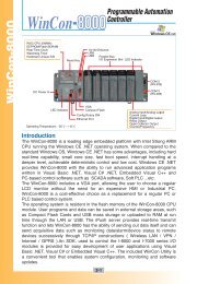
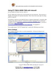
functions for ease of use within the different applications. The powerful functions of theLinPAC-8000 embedded controller are depicted in figure 1-1, which includes a VGA,USB(Card Reader, Camera …), Mouse, Keyboard, microSD/microSDHC card, Seriesports(RS-232, RS-485), Ethernet(Hub…) and many I/O slots in the picture. Presently,HTTP、FTP、Telnet、SSH、SFTP Servers are built in and users can transfer files or useremote control with the LinPAC-8000 more conveniently. In network communication,wireless, Bluetooth transfer and Modem, GPRS, ADSL, Firewall are also supported. Fig.1-2 illustrates hardware architecture of the LinPAC-8000.Fig. 1-1LinPAC-8x4x SDK:7
LP-8x41 SeriesFig. 1-2LinPAC-8x4x SDK:8
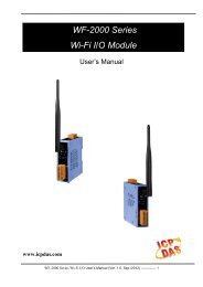
2. Installation of LinPAC-8000 SDK“LinPAC-8000 SDK” consists of the following major items.• LinPAC SDK library files• LinPAC SDK include files• Demo files• GNU ToolChainFrom ftp://ftp.icpdas.com/pub/cd/linpac/napdos/lp-8x4x/sdk/, users can download thelatest version of LinPAC-8000 SDK (hereinafter referred to as LP-8000 or LP-8K). Thenfollows below steps to install the development toolkit provided by <strong>ICP</strong> <strong>DAS</strong> for theapplication development of the LinPAC-8000 embedded controller platform easily.2.1 Quick Installation of LinPAC-8000 SDK(1) Quick Installation Guide for Windows1. Please insert the installation CD into your CD-ROM driver.2. Run the “lp8x4x_sdk_for_windows.exe” file under the folder \napdos\lp-8x4x\SDK\.Then click on the “Next” button, refer to Fig. 2-1.3. Choose the option of “I accept the agreement” and click the “next” button, refer toFig. 2-2 below.Fig. 2 -1 Fig. 2-24. To starting install the LinPAC-8000 SDK, refer to Fig 2-3.5. After successfully installing the software, please click on the “Finish” button to finishthe development toolkit installation, refer to Fig. 2-4.LinPAC-8x4x SDK:9
Fig. 2-3 Fig. 2-46. Open the “C:\cygwin\LinCon8k” folder and see the content. Refer to Fig 2-5.Fig. 2-57. Start using the “LinPAC-8000 Build Environment” by double clicking the shortcut forthe “LinPAC-8000 Build Environment” on the desktop or by clicking through“ Start ”>” Programs ”>” <strong>ICP</strong><strong>DAS</strong> ”>” LinPAC-8000 SDK ”>” LinPAC-8000 BuildEnvironment ” icon. Then a special DOSBOX will be displayed in which we cancompile applications for the LinPAC-8000. refer to Fig. 2-6.Fig. 2-6Once your Installation is complete, you can find the files for the library and demo in thefollowing paths.The Libi8k.a path is “C:\cygwin\LinCon8k\lib".The include files path is “C:\cygwin\LinCon8k\include”The demo path is “C:\cygwin\LinCon8k\examples”.LinPAC-8x4x SDK:10
(2) Quick Installation Guide for Linux1. Before you install LinPAC-8x4x SDK, you must complete several tasks as the rootuser by ‘sudo’ or ‘su’ command.2. Download the “lp8x4x_sdk_for_linux.tar.bz2” file under the folder\napdos\lp-8x4x\SDK\.3. Enter the following commands to extract the file:$ bzip2 -d lp8x4x_sdk_for_linux.tar.bz2$ tar jxvf lp8x4x_sdk_for_linux.tar4. To run the shell startup script and set the environment variables, enter the followingcommand:$ . /lincon/linpac.sh2.2 The LinPAC-8000 SDK IntroductionIn this section, we will discuss some techniques that are adopted in the LinPAC-8000.Through our detailed explanations, users can learn how to use the LinPAC-8000 easily.LinPAC-8000 SDK is based on cygwin and it is also a Linux-like environment for Windows.It still provides a powerful GCC cross-compiler and an IDE (Integrated DevelopmentEnvironment ) for developing LinPAC-8000 applications quickly. Therefore after you havewritten your applications, you can compile them through the LinPAC-8000 SDK intoexecutable files that can be run in your LinPAC-8000 embedded controller.LinPAC-8x4x SDK:11
2.2.1 Introduction to CygwinWhat is Cygwn ? Cygwin is a collection of free software tools originally developed byCygnus Solutions to allow various versions of Microsoft Windows to act somewhat like aUNIX system. That is Cygwin is a Linux-like environment for Windows. It consists of twoparts:(1) A DLL (cygwin1.dll) which acts as a Linux emulation layer providing substantial LinuxAPI functionality.(2) A collection of tools, which provide users with the Linux look and feel.2.2.2 Introduction to Cross-CompilationWhat is Cross-Compilation? Generally, compiling a program takes place by runningthe compiler on the build platform. The compiled program will run on the target platform.Usually these two processes are on the same platform; if they are different, the process iscalled cross-compilation. That is the process that can compile source code on one platformto the executable files on other platforms. For example, you can compile source code in ax86 windows platform into an executable file that can run on an arm-linux platform if youuse the cross-compiler - “arm-linux-gcc”.So why do we use Cross-Compilation? In fact, Cross-Compilation is sometimes moreinvolved and errors are easier to make than with normal compilation. Therefore it is oftenonly employed if the target is not able to compile programs on its own or when we want tocompile large programs that need more resources than the target can provide. For manyembedded systems, cross-compilation is the only possible way.2.2.3 Download the LinPAC-8x4x SDK For Windows system : (Extract the .exe file into to the C: driver.)linpacsdk_for_windows.exe as below:ftp://ftp.icpdas.com/pub/cd/linpac/napdos/lp-8x4x/sdk/linpacsdk_for_windows.exe For Linux system : (Extract the .bz2 file into to the root ( / ) directory.)linpacsdk_for_linux.tar.bz2 as below:ftp://ftp.icpdas.com/pub/cd/linpac/napdos/lp-8x4x/sdk/linpacsdk_for_linux.tar.bz2Note: We recommend user to change user ID to become root by ‘sudo’ or ‘su’ command.LinPAC-8x4x SDK:12
3.The Architecture of LIBI8K.A in the LinPAC-8000The libi8k.a is a library file that is designed for I7000/8000/87000 applications runningin the LinPAC-8000 Embedded Controller using the Linux OS. <strong>User</strong>s can apply it todevelop their own applications with GNU C language. In order to assist users to build theirproject quickly, we provide many demo programs. Based on these demo programs, userscan easily understand how to use these functions and develop their own applications withina short period of time.The relationships among the libi8k.a and user’s applications are depicted as Fig. 3-1:I-7000/8000/87000series ModulesfunctionsFig. 3-1Functions for LinPAC-8000 Embedded Controller are divided into sub-groups for easeof use within the different applications:1. System Information Functions 5. Analog Input Functions2. Digital Input/Output Functions 6. Analog Output Functions3. Watch Dog Timer Functions 7. 3-axis Encoder Functions4. EEPROM Read/Write Functions 8. 2-axis Stepper/Servo FunctionsThe functions in the Libi8k.a are specially designed for LinPAC-8000. <strong>User</strong>s can easilyfind the functions they need for their applications from the descriptions in chapter 6 and inthe demo programs provided in chapter 7.LinPAC-8x4x SDK:13
4. LinPAC-8000 System SettingsIn this section, we will introduce how to setup the LinPAC-8000 configuration. Letusers can use the LinPAC-8000 more easily.4.1 Settings for the LinPAC-8000 NetworkThe LinPAC-8000 network setting includes two ways. One is DHCP and the other is“Assigned IP”. DHCP is the default setting after the LinPAC-8000 is produced and this wayis easy for users. However, if your network system is without DHCP server, then usersneed to configure the network setting by using “Assigned IP”.4.1.1 Setting the IP、Netmask and Gateway(1) Using DHCP :Boot up LinPAC-8000 and click the “ start/xterm ” to open a “ commandPrompt ”. Type in “ vi /etc/network/interfaces ” to open the network setting file.Remove “ # ” in the dhcp block and add “ # ” in the Assign IP block. Then type“ :wq ” to save the setting. Type “ ifup eth0 ” to make the setting work. ( Refer tothe Fig 4-1 )Fig 4-1LinPAC-8x4x SDK:14
(2) Using “Assigned IP” :Boot up LinPAC-8000 and click the “ start/xterm ” to open a “command line”.Type in “ vi /etc/network/interfaces ” to open the network setting file. Remove “ # ”in the Assign IP block and add “ # ” in the dhcp block. Type ip、netmask and gatewayyou want in the Assign IP block. Then type “ :wq ” to save the setting. Type “ ifupeth0 “ to make the setting work. ( Refer to the Fig 4-2 )Fig 4-2After finish the LinPAC network setting, users can type “ ifconfig “ to see the networksetting. ( Refer to the Fig 4-3 )Fig 4-3LinPAC-8x4x SDK:15
4.1.2 Setting of DNSBoot up LinPAC-8000 and click the “ start/xterm ” to open a “command line”. Type in“ vi /etc/resolv.conf ” to open the DNS setting file. Type “ DNS server ” in the“ nameserver ” field. Then type “ :wq ” to save the setting. Type “ reboot ” to reboot theLinPAC-8000 to make the setting work. ( Refer to the Fig 4-4 )Fig 4-44.2 microSD Card Usage<strong>User</strong>s can access the files of microSD card in the /mnt/hda directory (Refer to Fig 4-5).Fig 4-5When using the microSD card, pay attention to the following notes:1. Umount the microSD card before unplugging it.2. Please do not power off or reboot the LP-8x4x while data is being written to or readfrom the microSD card.3. The microSD memory must be formatted in the VFAT/EXT2/EXT3 file system.4.2.1 Mount microSD CardIf want to use the microSD card, you can insert the microSD card into the socket in theLinPAC-8000 (Refer to Fig. 1-3). It will be auto-mounted in the LinPAC-8000 at boot time,and you can access the files of SD card in the /mnt/hda directory.If not, type in “/etc/init.d/sd start ”, user can mount microSD card by <strong>manual</strong>.LinPAC-8x4x SDK:16
4.2.2 Umount microSD CardBefore you want to pull out the microSD card from the LinPAC-8000, please type thefollowing steps:(1) /etc/init.d/startx stop(2) /etc/init.d/apachect1 stop(3) umount /mnt/hdaThen you can unplug the microSD card safely to prevent the damage to microSD card.4.2.3 Scan and repair microSD CardThe microSD card at boot will be named “ /dev/mmcblk0p1 “. <strong>User</strong> could be umountmicroSD card first before scan or repair microSD card. blockdev : call block device ioctls from the command lineex. blockdev --report /dev/mmcblk0p1 (print a report for device)blockdev -v --getra --getbz /dev/mmcblk0p1 (get readhead and blocksize) fsck.minix : perform a consistency check for the Linux MINIX filesystemex. fsck.minix -r /dev/mmcblk0p1(performs interactive repairs)fsck.minix -s /dev/mmcblk0p1(outputs super-block information) fsck.vfat : check and repair MS-DOS file systemsex. fsck.vfat -a /dev/mmcblk0p1 (automatically repair the file system)fsck.vfat -l /dev/mmcblk0p1 (list path names of files being processed) mkfs : build a Linux file system on a device, usually a hard disk partition.ex. mkfs -t vfat /dev/mmcblk0p1 (specifies the type of file system to be built)mkfs -c vfat /dev/mmcblk0p1(check the device for bad blocks before building the file system) mkfs.minix : make a MINIX filesystemex. mkfs.minix /dev/mmcblk0p1 (create a Linux MINIX file-system)mkfs.minix -c /dev/mmcblk0p1(check the device for bad blocks before creating the file system) mkfs.vfat : make an MS-DOS filesystemex. mkfs.vfat -A /dev/mmcblk0p1 (use Atari variation of the MS-DOS filesystem)mkfs.vfat -v /dev/mmcblk0p1 (verbose execution)LinPAC-8x4x SDK:17
4.3 USB Storage Device Usage<strong>User</strong>s need to mount the USB storage device to the LinPAC-8000, before they canaccess the USB storage device. This is because it will not auto-mount the USB storagedevice in the LinPAC-80004.3.1 Mount USB Storage DeviceThe steps are as follows :(1) Type “ mkdir /mnt/usb “ to build a usb directory.(2) Type “ mount /dev/sda1 /mnt/usb “ to mount the USB storage device to theusb directory and type “ ls /mnt/usb ” to see the content of USB storage device.4.3.2 Umount USB Storage DeviceBefore users pull out the USB storage device from the LinPAC-8000, users need totype the “ umount /mnt/usb “ command first. Then pull out the USB storage device toprevent any damage to usb storage device.4.4 Adjust VGA ResolutionThere are two modes -- 640x480、800x600 supported in the LinPAC VGA resolutionand the default setting is 800x600. If users want to change the VGA resolution. Pleasefollow below steps :(1) Type “ vi /etc/init.d/fbman ” to open resolution setting file.(2) If users want to set the resolution to be 640x480. First, add “ # ” in the 800x600column and then remove “ # ” in the 640x480 column. Type “ :wq ” to save thesetting. ( Refer to Fig 4-6 ) Open the file : /etc/init.d/fbman, user will see the following lines:#/usr/sbin/fbset -n 640x480-60/usr/sbin/fbset -n 800x600-70It means that the resolution setting is 800x600.LinPAC-8x4x SDK:18
If user want to change the setting to be 640*480, please see the followingsetting result :/usr/sbin/fbset -n 640x480-60#/usr/sbin/fbset -n 800x600-70Fig 4-6(3) Type “ reboot ” to reboot LinPAC-8000, and you will find the new setting. ( Refer toFig 4-7 )Fig 4-7LinPAC-8x4x SDK:19
4.5 Running applications automatically at boot timeA “run level” determines which programs are executed at system startup. Run level 2 isthe default run level of LinPAC-8000.The contents of run level are in the /etc/init.d directory that directory contains thescripts executed at boot time. These scripts are referenced by symbolic links in the/etc/rc2.d.These links are named S. The numbers determinethe order in which the scripts are run, from 00 to 99 — the lower number would earlierexecuted. Scripts named with an S are called with start, and named with a K or x are calledwith stop.4.5.1 Making program run at boot timeMaking program run at boot time, you should create a startup script placed in /etc/init.ddirectory that runs the required commands for executed automatically at boot time and besymbolically linked to /etc/rc2.d directory.The steps are as follows :(1) Type “ vi /etc/init.d/hello “ to edit a script that would like to executed program,filename is hello. Type “ :wq “ to save and quit the script. ( Refer to the Fig 4-8 )(2) Type “ chmod 755 /etc/init.d/hello “ to change authority.(3) Type “ cd /etc/rc2.d “ to into default run level.(4) Type ” ln -s ../init.d/hello /etc/rc2.d/S85hello “ to make a symbolic link intothe script file and it will be executed automatically at boot time. ( Refer to the Fig4-9 )LinPAC-8x4x SDK:20
Fig. 4-8LinPAC-8x4x SDK:21
Fig. 4-94.5.2 Disabling program run at boot timeThe steps are as follows :(1) Type “ cd /etc/rc2.d “ to into default run level.(2) Type “ mv S85hello xS85hello “ to rename the S85hello symbolic link for turnoff running program automatically at boot time.LinPAC-8x4x SDK:22
4.6 Automatic loginLog the specified user onto the console (normally /dev/tty1) when the system is firstbooted without prompting for a username or password using mingetty command.The steps are as follows :(1) Login as root and edit /etc/inittab(2) Modify the entry for the first terminal― tty1Below user can see the modified part of LinPAC-8000 /etc/inittab file(Refer to the Fig4-10), and it will autologins into the root account after reboot the LinPAC-8000.Fig. 4-10LinPAC-8x4x SDK:23
5. Instructions for the LinPAC-8000In this section, some Linux instructions that are often used will be introduced. The useof these instructions in linux is very familiar with those in DOS and generally they are usedin lower case.5.1 Basic Linux Instructions5.1.1 ls : list the file information -> ( like dir in DOS )Parameter:(1) -l:list detailed information of file ( Example:ls -l )(2) -a:list all files including hidden files ( Example:ls -a )(3) -t:list the files that are arranged by time(from new to old)5.1.2 cd directory : Change directory -> ( like cd in DOS )Parameter:(1)..:move to the upper directory ( Example:cd .. )(2) ~:move back to the root directory ( Example:cd ~ )(3)/:divided sign (for examples:cd /root/i8k )5.1.3 mkdir:create the subdirectory -> ( like md in DOS )mkdir –parameter subdirectory( Example:mkdir owner )5.1.4 rmdir:delete(remove) the subdirectory and it must be empty ->( like rd in DOS )rmdir –parameter subdirectory( Example:rmdir owner )LinPAC-8x4x SDK:24
5.1.5 rm : delete file or directory -> ( like del or deltree in DOS )rm –parameter file ( or directory )Parameter:(1) i:it will show the warning message when deleting ( Example:rm -i test.exe )(2) r:delete directory despite that it isn’t empty ( Example:rm –r Test )(3) f:it will not show a warning message when deleting ( Example:rm -f test.exe )5.1.6 cp:copy file -> ( like copy in DOS )cp –parameter source file destination file( Example:cp test.exe /root/Test/test.exe )5.1.7 mv:move or rename file or directory -> ( like move or ren in DOS )mv –parameter source file ( or directory ) destination file ( or directory )( Example:mv test.exe test1.exe )( Example:mv test.exe /root/Test )5.1.8 pwd:show the current path5.1.9 who:show the on-line users5.1.10 chmod:change authority of filechmod ??? file -> ??? means owner:group:all usersFor example:chmod 754 test.exe7 5 4 -> 111(read, write, execute) 101(read, write, execute) 100(read,write, execute)The first number 7 :owner can read and write and execute filesThe second number 5:group can only read and execute filesThe third number 4 :all users can only read files5.1.11 uname:show the version of linuxLinPAC-8x4x SDK:25
5.1.12 ps:show the procedures that execute now5.1.13 ftp:transfer fileftp IPAdress ( Example:ftp 192.168.0.200 -> connet to ftp server )! :exit FTP back to pc temporarilyexit:back to ftpbin:transfer files in “binary” modeget:download file from LinPAC to PC ( Ex:get /mnt/hda/test.exe c:/test.exe )put:upload file from PC to LinPAC ( Ex:put c:/test.exe /mnt/hda/test.exe )bye:exit FTP5.1.14 telnet:connect to other PCtelnet IPAddress (Example:telnet 192.168.0.200->remote control LinPAC-8000 )5.1.15 date:show date and time5.1.16 netstat:show the state of networkParameter [ -a ]:list all states ( Example:netstat -a )5.1.17 ifconfig:show the ip and network mask ( like ipconfig in DOS )5.1.18 ping:check to see if the host in the network is aliveping IPAddress ( Example:ping 192.168.0.1 )5.1.19 clear:clear the screen5.1.20 passwd:change the password5.1.21 reboot:reboot the LinPACLinPAC-8x4x SDK:26
5.2 General GCC InstructionsGCC is a cross-compiler provided by GNU and it can compile source code written byANSI C or by Tranditional C into executable files. The executable file compiled by GCC canrun in different OSs and in different Hardware systems. Therefore GCC is very popularwithin the Unix system which is a large part of why its popularity is growing so well.Furthermore it is free, and therefore can be downloaded via your network with ease.First, Fig. 5-1 illustrates the compilation procedure within Linux:Fig. 5-1Second, we will list some GCC instructions to let users compile *.c to *.exe smoothlyand to explain the parameters for GCC in its compilation process.LinPAC-8x4x SDK:27
5.2.1 Compile without linking the LinPAC-8000 library(1) Purpose:*. c to *. exeCommand:arm-linux-gcc –o target source.cParameter:-o target:assign the name of output filesource.c:source code of CExample:arm-linux-gcc –o helloworld.exe helloworld.cOutput File:helloworld.exe(2) Purpose:*. c ... *.c to *. exeCommand:arm-linux-gcc –c source.cCommand:arm-linux-gcc –o target object.oParameter:-o target:assign the name of output filesource.c:source code of Cobject.o:object fileExample:arm-linux-gcc –c main.c helloworld.c hi.carm-linux-gcc –o main.exe main.o helloworld.o hi.oOutput File:main.exe5.2.2 Compile with linking the LinPAC-8000 library ( libi8k.a )(1) Purpose:*. c to *. oCommand:arm-linux-gcc –IincludeDIR -lm –c –o target source.c libraryParameter:LinPAC-8x4x SDK:28
-IincludeDir:the path of include files-lm:include math library ( libm.a )-c:just compile *.c to *.o ( object file )-o target:assign the name of output filesource.c:source code of Clibrary:the path of libraryExample:arm-linux-gcc –I. –I../include –lm –c –o test.o test.c ../lib/libi8k.aOutput File:test.o(2) Purpose:*. o to *. exeCommand:arm-linux-gcc –IincludeDIR -lm –o target source.o libraryParameter:-IincludeDir:the path of include files-lm:include math library ( libm.a )-o target:assign the name of output filesource.o:object filelibrary:the path of libraryExample:arm-linux-gcc –I. –I../include –lm –o test.exe test.o ../lib/libi8k.aOutput File:test.exe(3) Purpose:*. c to *. exeCommand:arm-linux-gcc –IincludeDIR -lm –o target source.c libraryParameter:-IincludeDir:the path of include files-lm:include math library ( libm.a )-o target:assign the name of output filesource.c:source code of Clibrary:the path of libraryExample:arm-linux-gcc –I. –I../include –lm –o test.exe test.c ../lib/libi8k.aOutput File:test.exeLinPAC-8x4x SDK:29
5.3 A Simple Example – Helloworld.cIn this section, we will introduce how to compile the helloworld.c to helloworld.exe andtransfer the helloworld.exe to the LinPAC-8000 by using FTP. Finally executes this file viathe Telnet Server on the LinPAC-8000. These steps can be accomplished in one pc withoutanother monitor for the LinPAC-8000. In this example, no <strong>ICP</strong> <strong>DAS</strong> modules are used. Ifyou want to use the modules of <strong>ICP</strong> <strong>DAS</strong> to control your system, you can refer to demo inthe chapter 7.These processes can be divided into three steps and thet are given as below:STEP 1 :( Compile helloworld.c to helloworld.exe )(1) Open LinPAC-8000 SDK ( refer to step 8 in section 2.1) and type“ cd examples/common ” to change the path toC:/cygwin/LinCon8k/examples/common. Type “dir/w” and you can see thehelloworld.c file. (refer to Fig.5-2)Fig. 5-2LinPAC-8x4x SDK:30
(2) Type in “arm-linux-gcc –o helloworld.exe helloworld.c“ to compile helloworld.c intohelloworld.exe. Then type “dir/w“ to see the helloworld.exe file. (refer to Fig.5-3)Fig. 5-3STEP 2 :( Transfer helloworld.exe to the LinPAC-8000 )There are two methods for transferring files to the LinPAC-8000:< Method one > By Using the “DOS Command Prompt”:(1) Open a “DOS Command Prompt” and type in the ftp IPAddress of the LinPAC-8000( Example:ftp 192.168.0.200) to connect to the FTP Server on the LinPAC-8000. Thentype the <strong>User</strong>_Name and Password ( “ root ” is the default value. ) to accomplishthe connection from the PC to the LinPAC-8000.(2) Before transferring your files to the LinPAC-8000, type in the “bin” command to makethe file transfer to the LinPAC-8000 in binary mode. (refer to Fig.5-4)Fig.5-4LinPAC-8x4x SDK:31
(3) Type in “ put C:/cygwin/LinCon8k/examples/common/helloworld.exehelloworld.exe ” to transfer helloworld.exe to the LinPAC-8000. If it shows themessage of “ Transfer complete ”, then the whole transferring process has beenaccomplished. If you need to disconnect from the LinPAC-8000, type in the “ bye ”command to return to the PC console. (refer to Fig.5-5).Fig.5-5< Method two > By Using FTP Software:(1) Open the FTP Software and add a ftp site to the LinPAC-8000. The <strong>User</strong>_Name andPassword default value is “ root ”. Then click the “Connect” button to connect to theftp server of the LinPAC-8000. (refer to Fig.5-6).Fig.5-6LinPAC-8x4x SDK:32
(2) Upload the file - Helloworld.exe to the LinPAC-8000. (refer to Fig.5-7).Fig.5-7(3) Choose helloworld.exe in the LinPAC-8000 and click the right button of mouse tochoose the “ Permissions ” option. Then type 777 into the Numeric textbox. (refer toFig.5-8 and Fig.5-9 ).Fig.5-8Fig.5-9LinPAC-8x4x SDK:33
STEP 3 :( Telnet to the LinPAC-8000 and execute program)(1) Open a “ DOS Command Prompt ” and then type in the telnet IPAddress of theLinPAC-8000 ( Example:telnet 192.168.0.200 ) to connect to the telnet server of theLinPAC-8000. Then type the <strong>User</strong>_Name and Password ( “ root ” is the defaultvalue. ). If it shows the “ # “ prompt character, the process of connecting from your PCto the telnet server of the LinPAC-8000 is finished. (refer to Fig.5-10)Fig.5-10(2) Type in the “ls -l“ command in order to list all the files in /root and to see thehelloworld.exe file. Then type in the “chmod 777 helloworld.exe” command tochange the authority of helloworld.exe and then type in the “ls -l“ command again tosee “helloworld.exe”. This means that the file is executable. Type in“./helloworld.exe“ to execute the file and it will show “ Welcome to LinPAC-8000 ”.Then all the steps from compile、 transfer to telnet to execute program will becompleted. (refer to Fig.5-11)Fig.5-11LinPAC-8x4x SDK:34
5.4 i-Talk UtilityThe i-Talk utility provides fifteen instructions that make it convenient for users toaccess the modules and hardware in the LinPAC-8000 and they are placed in the path -/usr/local/bin. Fig. 5-12 describes the functions of i-Talk utility.Fig. 5-12LinPAC-8x4x SDK:35
Fig. 5-13 lists the demo that show how to use the I-talk utility. In the demo, theI-8024W ( AO Module )、I-8017HW ( AI Module ) and I-8055W ( DIO Module) are all usedand they are plugged into the slots 1、2 and 3 of the LinPAC seperately.Fig. 5-13<strong>User</strong>s can also type in the instructions name and it will show the instructions usage.LinPAC-8x4x SDK:36
6. LIBI8K.AIn this section, we will focus on examples for the description of and application of thefunctions found in the Libi8k.a. The Libi8k.a functions can be clarified into 3 groupswhich are listed in Fig. 6-1Fig. 6-1Functions (1) and (2) in the Libi8k.a are the same as with the DCON.DLL Driver( including Uart.dll and I7000.dll ) as used in the DCON modules ( I-7000 / I-8000 / I-87000in serial communication ). You can refer to the DCON.DLL Driver <strong>manual</strong> which includesthe functions on how to use DCON modules. The DCON.DLL Driver has already beenwrapped into the Libi8k.a. Functions (3) of the Libi8k.a consist of the most importantfunctions as they are specially designed for I-8000 modules in the LinPAC-8000 slots.They are different from functions (1) and (2) because the communication of I-8000modules in the LinPAC-8000 slots are parallel and not serial. Therefore <strong>ICP</strong> <strong>DAS</strong> rewroteI8000.c to Slot.c especially for I-8000 modules in the LinPAC-8000 slots. Here we willintroduce all the funcitions for slot.c and they can be divided into eight parts for ease ofuse.LinPAC-8x4x SDK:37
1. System Information Functions;2. Digital Input/Output Functions;3. Watch Dog Timer Functions;4. EEPROM Read/Write Functions;5. Analog Input Functions;6. Analog Output Functions;7. 3-axis Encoder Functions;8. 2-axis Stepper/Servo Functions;When using the development tools to develop applications, the msw.h file must beincluded in front of the source program, and when building applications, Libi8k.a must belinked. If you want to control <strong>ICP</strong> <strong>DAS</strong> I/O remote modules like i7k, i8k and i87k throughCOM2 or COM3 or COM4 of the LinPAC-8000, the functions are all the same with DCONDLL. And if you want to control i8k modules that are plugged in the slots of theLinPAC-8000, then the functions are different and they are described as follows :6.1 System Information Functions• Open_SlotDescription:This function is used to open and initiate a specified slot in the LinPAC-8000. The 8k orI-87k modules in the LinPAC-8000 will use this function. For example, if you want to sendor receive data from a specified slot, this function must be called first. Then the otherfunctions can be used later.Syntax:int Open_Slot(int slot)[ C ]Parameter:slot : [Input] Specify the slot number in which the I/O module is plugged into.Return Value:0 is for SuccessNot 0 is for FailureLinPAC-8x4x SDK:38
Example:Int slot=1;Open_Slot(slot);// The first slot in the LinPAC-8000 will be open and initiated.Remark:• Close_SlotDescription:If you have used the function of Open_Slot() to open the specified slot in theLinPAC-8000, you need to use the Close_Slot() function to close the specified slot in theLinPAC-8000. The 8k or I-87k modules in the LinPAC-8000 will use this function. Forexample, once you have finished sending or receiving data from a specified slot, thisfunction would then need to be called.Syntax:void Close_Slot(int slot)[ C ]Parameter:slot :Return Value:[Input] Specify the slot number in which the I/O module is plugged into.NoneExample:int slot=1;Close_Slot(slot);// The first slot in the LinPAC-8000 will be closed.Remark:LinPAC-8x4x SDK:39
• Open_SlotAllDescription:This function is used to open and initiate all slots in the LinPAC-8000. For example, ifyou want to send or receive data from multiple slots, you can call this function to simplifyyour program. Then you can use the other functions later.Syntax:int Open_Slot(void)[ C ]Parameter:NoneReturn Value:0 is for SuccessNot 0 is for FailureExample:Open_SlotAll();// All slots in the LinPAC-8000 will be open and initiated.Remark:• Close_SlotAllDescription:If you have used the function Open_SlotAll() to open all the slots in the LinPAC-8000,you can use the Close_SlotAll() function to close all the slots in the LinPAC-8000. Forexample, once you are finish sending or receiving data from many slots, this function canbe called to close all the slots rapidly.Syntax:void Close_SlotAll(void)[ C ]LinPAC-8x4x SDK:40
Parameter:NoneReturn Value:NoneExample:Close_Slot();// All slots in the LinPAC-8000 will be closed.Remark:• ChangeToSlotDescription:This function is used to dedicate serial control to the specified slots for the control ofthe I-87k series. The serial bus in the LinPAC-8000 backplane is for mapping through toCOM1. For example, if you want to send or receive data from a specified slot, you need tocall this function first. Then you can use the other series functions.Syntax:void ChangeToSlot(char slot)[ C ]Parameter:slot :Return Value:[Input] Specify the slot number in which the I/O module is plugged into.NoneExample:char slot=2;ChangeToSlot (slot);// The first slot is specified as COM1 port in LinPAC-8000.Remark:LinPAC-8x4x SDK:41
• Open_ComDescription:This function is used to configure and open the COM port. It must be called oncebefore sending/receiving command through COM port. For example, if you want to send orreceive data from a specified COM port, you need to call this function first. Then you canuse the other series functions.Syntax:[ C ]WORD Open_Com(char port, DWORD baudrate, char cData, char cParity, char cStop)Parameter:port : [Input] COM1, COM2, COM3..., COM255.baudrate: [Input] 1200/2400/4800/9600/19200/38400/57600/115200cDate : [Input] Data5Bit, Data6Bit, Dat7Bit, Data8BitcParity : [Input] NonParity, OddParity, EvenParitycStop : [Input] OneStopBit, TwoStopBitReturn Value:0 is for SuccessNot 0 is for FailureExample:Open_Com(COM3, 9600, Data8Bit, NonParity, OneStopBit);Remark:LinPAC-8x4x SDK:42
• Close_ComDescription:This function is used to closes and releases the resources of the COM port computerrescourse. And it must be called before exiting the application program. TheOpen_Com will return error message if the program exit without calling Close_Comfunction.Syntax:BOOL Close_Com(char port)[ C ]Parameter:port :[Input] COM1,COM2, COM3...COM255.Return Value:NoneExample:Close_Com (COM3);Remark:LinPAC-8x4x SDK:43
• Send_Receive_CmdDescription:This function is used to sends a command string to RS-485 network and receives theresponse from RS-485 network. If the wChkSum=1, this function automatically adds thetwo checksum bytes into the command string and also check the checksum status whenreceiving response from the modules. Note that the end of sending string is added [0x0D]to mean the termination of every command.Syntax:[ C ]WORD Send_Receive_Cmd (char port, char szCmd[ ], char szResult[ ],WORD wTimeOut, WORD wChksum, WORD *wT)Parameter:port : [Input] 1=COM1, 2=COM2, 3=COM3..., 255=COM255.szCmd: [Input] Sending command stringszResult : [Input] Receiving the response string from the moduleswTimeOut :: [Input] Communicating timeout setting, the unit=1mswChkSum :: [Input] 0=Disable, 1=Enable*wT: [Output] Total time of send/receive interval, unit=1 msReturn Value:0 is for SuccessNot 0 is for FailureExample:char m_port =1;DWORD m_baudrate=115200;WORD m_timeout=100;WORD m_chksum=0;WORD m_wT;char m_szSend[40], m_szReceive[40];int RetVal;m_szSend[0] = '$';m_szSend[1] = '0';m_szSend[2] = '0';m_szSend[3] = 'M';LinPAC-8x4x SDK:44
m_szSend[4] = 0;/* open device file */Open_Slot(1);RetValue = Open_Com(m_port, m_baudrate, Data8Bit, NonParity, OneStopBit);if (RetValue >0) {printf("Open COM%d failed!\n", m_port);return FAILURE;}RetValue = Send_Receive_Cmd(m_port, m_szSend, m_szReceive, m_timeout,m_chksum, &m_wT);if (RetValue) {printf("Module at COM%d Address %d error !!!\n", m_port, m_szSend[2] );return FAILURE;}Close_Com (m_port);LinPAC-8x4x SDK:45
• Send_CmdDescription:This function only sends a command string to DCON series modules. If thewChkSum=1, it automatically adds the two checksum bytes to the command string.And then the end of sending string is further added [0x0D] to mean the termination of thecommand (szCmd). And this command string cannot include space char within thecommand string. For example: “$01M 02 03” is user’s command string. However, the actualcommand send out is “$01M”.Syntax:[ C ]WORD Send_Cmd (char port, char szCmd[ ], WORD wTimeOut, WORD wChksum)Parameter:port : : [Input] 1=COM1, 2=COM2, 3=COM3..., 255=COM255.szCmd : [Input] Sending command stringwTimeOut : [Input] Communicating timeout setting, the unit=1mswChkSum : [Input] 0=Disable, 1=EnableReturn Value:NoneExample:char m_port=1, m_szSend[40];DWORD m_baudrate=115200;WORD m_timeout=100, m_chksum=0;m_szSend[0] = '$';m_szSend[1] = '0';m_szSend[2] = '0';m_szSend[3] = 'M';Open_Slot(2); // The module is plug in slot 2 and address is 0.Open_Com(m_port, m_baudrate, Data8Bit, NonParity, OneStopBit);Send _Cmd(m_port, m_szSend, m_timeout, m_chksum);Close_Com (m_port);Remark:LinPAC-8x4x SDK:46
• Receive_CmdDescription:This function is used to obtain the responses string from the modules in RS-485network. And this function provides a response string without the last byte [0x0D].Syntax:[ C ]WORD Receive_Cmd (char port, char szResult[ ], WORD wTimeOut,WORD wChksum)Parameter:port : : [Input] 1=COM1, 2=COM2, 3=COM3..., 255=COM255.szResult : : [Output] Sending command stringwTimeOut : [Input] Communicating timeout setting, the unit=1mswChkSum : [Input] 0=Disable, 1=EnableReturn Value:NoneExample:char m_port=3;char m_Send[40], m_szResult[40] ;DWORD m_baudrate=115200;WORD m_timeout=100, m_chksum=0;m_szSend[0] = '$';m_szSend[1] = '0';m_szSend[2] = '1';m_szSend[3] = 'M';m_szSend[4] = 0;Open_Com (m_port, m_baudrate, Data8Bit, NonParity, OneStopBit);Send _Cmd (m_port, m_szSend, m_timeout, m_chksum);Receive_Cmd (m_port, m_szResult, m_timeout, m_chksum);Close_Com (m_port);// Read the remote module:I-7016D , m_ szResult : “!017016D”Remark:LinPAC-8x4x SDK:47
• Send_BinaryDescription:Send out the command string by fix length, which is controlled by the parameter “iLen”.The difference between this function and Send_cmd is that Send_Binary terminates thesending process by the string length “iLen” instead of the character "CR"(Carry return).Therefore, this function can send out command string with or without null character underthe consideration of the command length. Besides, because of this function without anyerror checking mechanism (Checksum, CRC, LRC... etc.), users have to add the errorchecking information to the raw data by themselves if communication checking system isrequired. Note that this function is usually applied to communicate with the other device,but not for <strong>ICP</strong> <strong>DAS</strong> DCON (I-7000/8000/87K) series modules.Syntax:[ C ]WORD Send_Binary (char port, char szCmd[ ], int iLen)Parameter:port :szCmd :iLen :: [Input] 1=COM1, 2=COM2, 3=COM3..., 255=COM255.[Input] Sending command string[Input] The length of command string.Return Value:NoneExample:int m_length=4;char m_port=3, char m_szSend[40];DWORD m_baudrate=115200;m_szSend[0] = '0';m_szSend[1] = '1';m_szSend[2] = '2';m_szSend[3] = '3';Open_Com(m_port, m_baudrate, Data8Bit, NonParity, OneStopBit);Send _Binary(m_port, m_szSend, m_length);Close_Com (m_port);Remark:LinPAC-8x4x SDK:48
• Receive_BinaryDescription:This function is applied to receive the fix length response. The length of the receivingresponse is controlled by the parameter “iLen”. The difference between this function andReceive_cmd is that Receive_Binary terminates the receiving process by the string length“iLen” instead of the character "CR"(Carry return). Therefore, this function can be used toreceive the response string data with or without null character under the consideration ofreceiving length. Besides, because of this function without any error checking mechanism(checksum, CRC, LRC... etc.), users have to remove from the error checking informationfrom the raw data by themselves if communication checking system is used. Note that thisfunction is usually applied to communicate with the other device, but not for <strong>ICP</strong> <strong>DAS</strong>DCON (I-7000/8000/87K) series modules.Syntax:[ C ]WORD Receive_Binary (char cPort, char szResult[], WORD wTimeOut,WORD wLen, WORD *wT)Parameter:port : : [Input] 1=COM1, 2=COM2, 3=COM3..., 255=COM255.szResult : [Input] Receiving the response string from the moduleswTimeOut :: [Input] Communicating timeout setting, the unit=1mswLen : [Input] The length of command string.*wT: [Output] Total time of send/receive interval, unit=1 msReturn Value:NoneExample:int m_length=10;char m_port=3;char m_szSend[40];char m_szReceive[40];DWORD m_baudrate=115200;WORD m_wt;WORD m_timeout=10;LinPAC-8x4x SDK:49
WORD m_wlength=10;m_szSend[0] = '0';m_szSend[1] = '1';m_szSend[2] = '2';m_szSend[3] = '3';m_szSend[4] = '4';m_szSend[5] = '5';m_szSend[6] = '6';m_szSend[7] = '7';m_szSend[8] = '8';m_szSend[9] = '9';Open_Com(m_port, m_baudrate, Data8Bit, NonParity, OneStopBit);// send 10 characterSend _Binary(m_port, m_szSend, m_length);// receive 10 characterReceive_Binary( m_port, m_szResult, m_timeout, m_wlength, &m_wt);Close_Com (m_port);Remark:LinPAC-8x4x SDK:50
• sio_openDescription:This function is used to open and initiate a specified serial port in the LinPAC-8000.The n-port modules in the LinPAC-8000 will use this function. For example, if you want tosend or receive data from a specified serial port, this function must be called first. Then theother functions can be used later.Syntax:[ C ]int sio_open(const char *port, speed_t baudrate, tcflag_t data, tcflag_t parity,tcflag_t stop)Parameter:port : [Input] device name: /dev/ttyS2, /dev/ttyS3…/dev/ttyS34baudrate: [Input] B1200/ B2400/ B4800/ B9600/ B19200/ B38400/ B57600/B115200date : : [Input] DATA_BITS_5/ DATA_BITS_6/ DATA_BITS_7/ DATA_BITS_8parity : : [Input] NO_PARITY / ODD_PARITY / EVEN_PARITYstop : : [Input] ONE_STOP_BIT / TWO_STOP_BITSReturn Value:This function returns int port descriptor for the port opened successfully.ERR_PORT_OPEN is for FailureExample:#define COM_M1 "/dev/ttyS2" // Defined the first port of I-8144 in slot 1char fd[5];fd[0]=sio_open(COM_M1, B9600, DATA_BITS_8, NO_PARITY,ONE_STOP_BIT);if (fd[0] == ERR_PORT_OPEN) {printf("open port_m failed!\n");return (-1);}// The i8114 is plug in slot 1 and the first port will be open and initiated.Remark:This function can be applied on modules: I-8114, I-8112, I-8142 and I-8144.LinPAC-8x4x SDK:51
• sio_closeDescription:If you have used the function of sio_open() to open the specified serial port in theLinPAC-8000, you need to use the sio_close() function to close the specified serial port inthe LinPAC-8000. For example, once you have finished sending or receiving data from aspecified serial port, this function would then need to be called.Syntax:int sio_close(int port)[ C ]Parameter:port :[Input] device name: /dev/ttyS2, /dev/ttyS3…/dev/ttyS34Return Value:NoneExample:#define COM_M2 "/dev/ttyS3" // Defined the second port of I-8144 in slot 1char fd[5];fd[0]=sio_open(COM_M2, B9600, DATA_BITS_8, NO_PARITY,ONE_STOP_BIT);sio_close (fd[0]);// The second port of i8144 in slot 1 will be closed.Remark:This function can be applied on modules: I-8114, I-8112, I-8142 and I-8144.LinPAC-8x4x SDK:52
• GetModuleTypeDescription:This function is used to retrieve which type of 8000 series I/O module is plugged into aspecific I/O slot in the LinPAC-8000. This function performs a supporting task in thecollection of information related to the system’s hardware configurations.Syntax:int GetModuleType(int slot)[ C ]Parameter:slot : [Input] Specify the slot number in which the I/O module is plugged into.Return Value:Module Type: it is defined in the IdTable[] of slot.c.TypeValue_PARALLEL 0x80_AI0xA0_AO0xA1_DI80xB0_DI160xB1_DI320xB2_DO60xC0_DO80xC1_DO160xC2_DO320xC3_DI4DO40xD0_DI8DO80xD1_DI16DO16 0xD2_MOTION0xE2_CAN0XF0Example:int slot=1;int moduleType;Open_Slot(slot);printf("GetModuleType= 0x%X \n", GetModuleType(slot));Close_Slot(slot);// The I-8057W card is plugged in slot 1 of LinPAC-8000 and has a return Value : 0xC2Remark:LinPAC-8x4x SDK:53
• GetNameOfModuleDescription:This function is used to retrieve the name of an 8000 series I/O module, which isplugged into a specific I/O slot in the LinPAC-8000. This function supports the collection ofsystem hardware configurations.Syntax:int GetNameOfModule(int slot)[ C ]Parameter:slot:[Input] Specify the slot number where the I/O module is plugged into.Return Value:I/O module ID. For Example, the I-8017 will return 8017.Example:int slot=1;int moduleID;Open_Slot(slot);moduleID=GetNameOfModule(slot);Close_Slot(slot);// The I-8017 card plugged in slot 1 of LinPAC-8000// Returned Value: moduleName=” 8017 ”Remark:LinPAC-8x4x SDK:54
• Read_SNDescription:This function is used to retrieves the hardware serial identification number on theLinPAC-8000 main controller. This function supports the control of hardware versions byreading the serial ID chipSyntax:[ C ]void Read_SN(unsigned char serial_num[])Parameter:serial_num : [Output] Receive the serial ID number.Return Value:NoneExample:int slot ;unsigned char serial_num[8];Open_Slot(0);Read_SN(serial_num);printf("SN=%x%x%x%x%x%x%x%x\n",serial_num[0],serial_num[1], serial_ num[2],serial_num[3],serial_num[4],serial_num[5],serial_num[6],serial_num[7]);Remark:• SetLEDDescription:This function is used to turn the LinPAC-8000 LED’s on/off.Syntax:void SetLED(unsigned int led)[ C ]LinPAC-8x4x SDK:55
Parameter:led :Return Value:[Input] 1 : Turn on the LED0 : Turn off the LEDNoneExample:unsigned int led;led=1;SetLED(led);// The LED will turn on in LinPAC-8000.Remark:• GetBackPlaneIDDescription:This function is used to retrieve the back plane ID number in the LinPAC-8000.Syntax:int GetBackPlaneID()[ C ]Parameter:NoneReturn Value:Backplane ID number.Example:int id;id=GetBackPlaneID();printf("GetBackPlanel =%d \n", id);// Get the LinPAC-8000 backplane id . Returned Value: GetBackPlanel = 2Remark:LinPAC-8x4x SDK:56
• GetSlotCountDescription:This function is used to retrieve the number of slot in the LinPAC-8000.Syntax:int GetSlotCount()[ C ]Parameter:NoneReturn Value:Number of slot.Example:int number;number= GetSlotCount();printf("GetSlotCount =%d \n", number);// Get the LinPAC-8841 slot count.// Returned Value: GetSlotCount = 8Remark:LinPAC-8x4x SDK:57
• GetDIPswitchDescription:This function is used to retrieve the DIP switch value in the LinPAC-8000.Syntax:int GetDIPswitch()[ C ]Parameter:NoneReturn Value:DIP switch value.Example:int value;value= GetDIPswitch();printf("GetDIPswitch =%d \n", value);// Get the LinPAC-8000 DIP switch value.// Returned Value: GetDIPswitch = 128Remark:This function can be applied on PAC: LinPAC-8441, LinPAC-8841.LinPAC-8x4x SDK:58
• GetRotaryIDDescription:This function is used to retrieve the rotary ID number in the LinPAC-8000.Syntax:int GetRotaryID(int type, & id)[ C ]Parameter:type :[Input] number of slot.idReturn Value:0 is for SuccessNot 0 is for FailureExample:int id, slot, type, wRetVal;switch(type){case 1:slot = 0; //lp-8x4xbreak;case 2:slot = 8;break;default:slot = 0;break;}wRetVal = Open_Slot(slot);if (wRetVal > 0) {printf("open Slot%d failed!\n",slot);return (-1);}id= GetRotaryID(slot);printf("GetRotaryID =%d \n",id); // Get the LinPAC-8000 rotary id. If user turn therotary switch to the 1 position, would get the returned value: GetRotaryID = 78Remark:LinPAC-8x4x SDK:59
• GetSDKversionDescription:This function is used to retrieve the version of LinPAC-8000 SDK.Syntax:float GetSDKversion(void)[ C ]Parameter:NoneReturn Value:Version number.Example:printf(" GetSDKversion = %4.2f \n ", GetSDKversion());// Get the LinPAC-8000 SDK version number.// Returned Value: GetSDKversion = 1.Remark:LinPAC-8x4x SDK:60
6.2 Watch Dog Timer Functions• EnableWDT• DisableWDTDescription:This function can be used to enable the watch dog timer (WDT) and users need toreset WDT in the assigned time set by users. Or LinPAC will reset automatically.Syntax:[C]void EnableWDT(unsigned int msecond)void DisableWDT(void)Parameter:msecond:LinPAC will reset in the assigned time if users don’t reset WDT.The unit is mini-second.Return Value:NoneExample:EnableWDT(10000); //Enable WDT interval 10000ms=10swhile (getchar()==10){printf("Refresh WDT\n");EnableWDT(10000); //Refresh WDT 10s}printf("Disable WDT\n");DisableWDT();Remark:LinPAC-8x4x SDK:61
• WatchDogSWEvenDescription:This function is used to read the LinPAC Reset Condition and users can reinstall theinitial value according to the Reset Condition.Syntax:[C]unsigned int WatchDogSWEven (void)Parameter:NoneReturn Value:Just see the last number of the return value – RCSR ( Reset Controller StatusRegister). For example : RCSR is “20009a4”, so just see the last number “4”. 4 is 0100 inbits and it means :Bit 0 : Hardware Reset ( Like : Power Off, Reset Button )Bit 1 : Software Reset ( Like : Type “Reboot” in command prompt )Bit 2 : WDT Reset ( Like : Use “EnableWDT(1000)” )Bit 3 : Sleep Mode Reset ( Not supported in the LinPAC )Example:printf("RCRS = %x\n", WatchDogSWEven() );Remark:LinPAC-8x4x SDK:62
• ClearWDTSWEvenDescription:This function is used to clear RCSR value.Syntax:[C]void ClearWDTSWEven (unsigned int rcsr)Parameter:rcsr : Clear bits of RCSR. Refer to the following parameter setting:1 : clear bit 02 : clear bit 14 : clear bit 28 : clear bit 3F : clear bit 0 ~ bit 3Return Value:NoneExample:ClearWDTSWEven(0xF) ; //Used to clear bit 0 ~ bit 3 of RCRS to be zero.Remark:LinPAC-8x4x SDK:63
6.3 EEPROM Read/Write Functions• Enable_EEPDescription:This function is used to make EEPROM able to read or write. It must be used beforeusing Read_EEP or Write_EEP. This EEPROM is divided into 256 blocks (0 to 255), andeach block is 64 bytes in length from offset 0 to 63.Syntax:void Enable_EEP(void)[ C ]Parameter:NoneReturn Value:NoneExample:Enable_EEP();// After using this function, you can use Write_EEP or Read_EEP to write or read// data of EEPROM.Remark:LinPAC-8x4x SDK:64
• Disable_EEPDescription:This function is used to make EEPROM unable to read or write. You need to use thisfunction after using Read_EEP or Write_EEP. Then it will protect you from modifying yourEEPROM data carelessly.Syntax:void Disable_EEP(void)[ C ]Parameter:NoneReturn Value:NoneExample:Disable_EEP();// After using this function, you will not use Write_EEP or Read_EEP to write or// read data of EEPROM.Remark:LinPAC-8x4x SDK:65
• Read_EEPDescription:This function will read one byte data from the EEPROM. There is a 16K-byte EEPROMin the main control unit in the LinPAC-8000 system. This EEPROM is divided into 256blocks (0 to 255), and each block is 64 bytes in length from offset 0 to 63. This EEPROMwith its accessing APIs provides another mechanism for storing critical data insidenon-volatile memory.Syntax:[ C ]unsigned char Read_EEP(int block, int offset)Parameter:block :offset:[Input] the block number of EEPROM.[Input] the offset within the block.Return Value:Data read from the EEPROM.Example:int block, offset;unsigned char data;data= ReadEEP(block, offset);// Returned value: data= read an 8-bit value from the EEPROM (block & offset)Remark:LinPAC-8x4x SDK:66
• Write_EEPDescription:To write one byte of data to the EEPROM. There is a 16K-byte EEPROM in the maincontrol unit of the LinPAC-8000 system. This EEPROM is divided into 256 blocks (0 to 255),and each block is 64 bytes in length from the offset of 0 to 63. This EEPROM with itsaccessing APIs, provides another mechanism for storing critical data inside non-volatilememory.Syntax:[ C ]void Write_EEP(int block, int offset, unsigned char data)Parameter:block :offset:Data:[Input] the block number of EEPROM.[Input] the offset within the block.[Input] data to write to EEPROM.Return Value:NoneExample:int block, offset;unsigned char data=10;WriteEEP(block, offset, data);// Writes a 10 value output to the EEPROM (block & offset) locationRemark:LinPAC-8x4x SDK:67
6.4 Digital Input/Output Functions6.4.1 For I-8000 modules via parallel port• DO_8Description:This function is used to output 8-bit data to a digital output module. The 0~7 bits ofoutput data are mapped into the 0~7 channels of digital module output respectively.Syntax:[ C ]void DO_8(int slot, unsigned char data)Parameter:slot :data :[Input] the slot number where the I/O module is plugged into.[Input] output data.Return Value:NoneExample:int slot=1;unsigned char data=3;DO_8(slot, data);// The I-8064 card is plugged in slot 1 of LinPAC-8000 and can turn on channel 0// and 1.Remark:This function can be applied on modules: I-8060W, I-8064W, I-8065W, I-8066W,I-8068W and I-8069W.LinPAC-8x4x SDK:68
• DO_16Description:This function is used to output 16-bit data to a digital output module. The 0~15 bits ofoutput data are mapped into the 0~15 channels of digital output modules respectively.Syntax:[ C ]void DO_16(int slot, unsigned int data)Parameter:slot :data :[Input] the slot number where the I/O module is plugged into.[Input] output data.Return Value:NoneExample:int slot=1;unsigned int data=3;DO_16(slot, data);// The I-8057 card is plugged in slot 1 of LinPAC-8000 and can turn on channel 0// and 1.Remark:This function can be applied on modules: I-8037W, I-8056W, I-8057W and I-8046W.LinPAC-8x4x SDK:69
• DO_32Description:Output the 32-bit data to a digital output module. The 0~31 bits of output data aremapped into the 0~31 channels of digital output modules respectively.Syntax:[ C ]void DO_32(int slot, unsigned int data)Parameter:slot :data :[Input] the slot number where the I/O module is plugged into.[Input] output data.Return Value:NoneExample:int slot=1;unsigned int data=3;DO_32(slot, data);// The I-8041W card is plugged in slot 1 of LinPAC-8000 and can turn on channel 0// and 1.Remark:This function can be applied on module: I-8041W.LinPAC-8x4x SDK:70
• DI_8Description:Obtains 8-bit input data from a digital input module. The 0~7 bits of input datacorrespond to the 0~7 channels of digital input modules respectively.Syntax:unsigned char DI_8(int slot)[ C ]Parameter:slot :[Input] the slot number where the I/O module is plugged into.Return Value:Input dataExample:int slot=1;unsigned char data;data=DI_8(slot);// The I-8058W card is plugged in slot 1 of LinPAC-8000 and has inputs in channel 0and 1.// Returned value: data=0xfCRemark:There are two kind of Input type:Input Type On State Off State Modules1 LED On, Readback as 1 LED Off, Readback as 0 I-8058W2 LED On, Readback as 0 LED Off, Readback as 1 I-8048W, I-8052WLinPAC-8x4x SDK:71
• DI_16Description:This function is used to obtain 16-bit input data from a digital input module. The 0 ~15bits of input data correspond to the 0~15 channels of digital module’s input respectively.Syntax:unsigned int DI_16(int slot)[ C ]Parameter:slot :[Input] the slot number where the I/O module is plugged into.Return Value:Input dataExample:int slot=1;unsigned int data;data=DI_16(slot);// The I-8053W card is plugged in slot 1 of LinPAC-8000 and has inputs in channel 0and 1.// Returned value: data=0xfffCRemark:There are two kind of Input type:Input Type On State Off State Modules1 LED On, Readback as 1 LED Off, Readback as 0 I-8046W2 LED On, Readback as 0 LED Off, Readback as 1I-8051W, I-8053W,I-8053PWLinPAC-8x4x SDK:72
• DI_32Description:This function is used to obtain 32-bit input data from a digital input module. The 0~31bits of input data correspond to the 0~31 channels of digital input module respectively.Syntax:unsigned long DI_32(int slot)[ C ]Parameter:slot :[Input] the slot number where the I/O module is plugged into.Return Value:Input dataExample:int slot=1;unsigned long data;data=DI_32(slot);// The I-8040 card plugged is in slot 1 of LinPAC-8000 and has inputs in// channels 0 and 1.// Returned value: data=0xfffffffCRemark:On State Off State ModulesInputType LED On, Readback as 0 LED Off, Readback as 1 I-8040WLinPAC-8x4x SDK:73
• DIO_DO_8Description:This function is used to output 8-bit data to DIO modules. These modules run 8 digitalinput channels and 8 digital output channels simultaneously. The 0~7 bits of output dataare mapped onto the 0~7 output channels for their specific DIO modules respectively.Syntax:[ C ]void DIO_DO_8(int slot, unsigned char data)Parameter:slot :data :[Input] the slot number where the I/O module is plugged into.[Input] output data.Return Value:NoneExample:int slot=1;unsigned char data=3;DIO_DO_8(slot, data);// The I-8054 card is plugged in slot 1 of LinPAC-8000 and can turn on channels 0// and 1.// It not only outputs a value, but also shows 16LEDs.Remark:This function can be applied in modules: I-8054W, I-8055W, and I-8063W.LinPAC-8x4x SDK:74
• DIO_DO_16Description:This function is used to output 16-bits of data to DIO modules, which have 16 digitalinput and 16 digital output channels running simultaneously. The 0~15 bits of output dataare mapped onto the 0~15 output channels for their specific DIO modules respectively.Syntax:[ C ]void DIO_DO_16(int slot, unsigned int data)Parameter:slot :data :[Input] the slot number where the I/O module is plugged into.[Input] output data.Return Value:NoneExample:int slot=1;unsigned int data=3;DIO_DO_16(slot, data);// The I-8042 card is plugged in slot 1 of LinPAC-8000 and can turn on the// channels 0 and 1.// It not only outputs a value, but also shows 32LEDs.Remark:This function can be applied on modules: I-8042W and I-8050W.LinPAC-8x4x SDK:75
• DIO_DI_8Description:This function is used to obtain 8-bit data from DIO modules. These modules run 8digital input and 8 digital output channels simultaneously. The 0~7 bits of intput data, aremapped onto the 0~7 iutput channels for their specific DIO modules respectively.Syntax:Unsigned char DIO_DI_8(int slot)[ C ]Parameter:slot :[Input] the slot number where the I/O module is plugged into.Return Value:Input dataExample:int slot=1;unsigned char data;data=DIO_DI_8(slot);// The I-8054W is plugged in slot 1 of LinPAC-8000 and has inputs in// channel 0 and 1.// Returned value: data=0xfCRemark:This function can be applied in modules: I-8054W, I-8055W and I-8063W.LinPAC-8x4x SDK:76
• DIO_DI_16Description:This function is used to obtain 16-bit data from DIO modules. These modules run 16digital input and 16 digital output channels simultaneously. The 0~15 bits of iutput data aremapped onto the 0~15 iutput channels for their specific DIO modules respectively.Syntax:Unsigned char DIO_DI_16(int slot)[ C ]Parameter:slot :[Input] the slot number where the I/O module is plugged into.Return Value:Input dataExample:int slot=1;unsigned char data;data=DIO_DI_16(slot);// The I-8042 card is plugged in slot 1 of LinPAC-8000 and has inputs in// channel 0 and 1.// Returned value: data=0xfffCRemark:This function can be applied in modules: I-8042W.LinPAC-8x4x SDK:77
• DO_8_RB、DO_16_RB、DO_32_RBDIO_DO_8_RB、DIO_DO_16_RBDescription:This function is used to Readback all channel status from a Digital Output module.Syntax:[ C ]unsigned char DO_8_RB(int slot)unsigned int DO_16_RB(int slot)unsigned long DO_32_RB(int slot)unsigned char DIO_DO_8_RB(int slot)unsigned int DIO_DO_16_RB(int slot)Parameter:slot :[Input] the slot number where the I/O module is plugged into.Return Value:all DO channel statusExample:int slot=1;Open_Slot(slot);printf("%u",DO_32_RB(slot));Close_Slot(slot);// The I-8041W module is plugged in slot 1 of LinPAC-8000 and return all DO channelstatus.Remark:These functions can be applied on modules:DO 8 channel:I-8060W, I-i8064W, I-8065W, I-8066W, I-8068W and I-8069W.DO 16 channel:I-8037W, I-8056W, I-8057W and I-8046W.DO 32 channel:I-8041WLinPAC-8x4x SDK:78
• DO_8_BW、DO_16_ BW、DO_32_ BWDIO_DO_8_ BW、DIO_DO_16_ BWDescription:This function is used to output assigned single channel status (ON / OFF) of a DigitalOutput module.Syntax:[ C ]void DO_8_BW(int slot, int bit, int data)void DO_16_BW (int slot, int bit, int data)void DO_32_BW (int slot, int bit, int data)void DIO_DO_8_BW (int slot, int bit, int data)void DIO_DO_16_BW (int slot, int bit, int data)Parameter:slot : [Input] the slot number where the I/O module is plugged into.bit : [Input] channel of module.data : [Input] channel status [ on(1) / off(0) ].Return Value:NoneExample:int slot=1, bit=0, data=1;Open_Slot(slot);DO_32_BW(slot, bit, data);Close_Slot(slot);// The I-8041W module is plugged in slot 1 of LinPAC-8000 and just turn on channel 0of I-8041W.Remark:These functions can be applied on modules:DO 8 channel:I-8060W, I-8064W, I-8065W, I-8066W, I-8068W and I-8069W.DO 16 channel:I-i8037W, I-8056W and I-8057WDO 32 channel:I-8041WLinPAC-8x4x SDK:79
• DI_8_BW、DI_16_ BW、DI_32_ BWDescription:This function is used to Readback assigned single channel status (ON / OFF) from aDigital Input module.Syntax:int DI_8_BW(int slot, int bit)int DI_16_BW (int slot, int bit)int DI_32_BW (int slot, int bit)[ C ]Parameter:slot :bit :[Input] the slot number where the I/O module is plugged into.[Input] channel of module.Return Value:NoneExample:int slot=1, bit=0;Open_Slot(slot);printf("DI channel %d = %d\n", bit, DI_32_BW(slot, bit));Close_Slot(slot);// The I-8040W module is plugged in slot 1 of LinPAC-8000 and return channel 0// status. ( 0:ON;1:OFF ).Remark:These functions can be applied on modules:DI 8 channel:I-8048W, I-8052W and I-8058W.DI 16 channel:I-8051W and I-8053WDI 32 channel:I-8040WLinPAC-8x4x SDK:80
• UDIO_WriteConfig_16Description:This function is used to configure the channel of the universal DIO module which isdigital input or digital output mode. The universal DIO module can be up to 16 digital inputor digital output channels running simultaneously.Syntax:[ C ]unsigned short UDIO_WriteConfig_16(int slot, unsigned short config)Parameter:slot : [Input] the slot number where the I/O module is plugged into.config : [Input] channel status.[ DO : 1 / DI : 0 ]Return Value:NoneExample:int slot=1;unsigned short config=0xffff;UDIO_WriteConfig_16(slot, config);// The I-8064 card is plugged in slot 1 of LinPAC-8000.// WriteConfig: 0xffff (ch 0~ch15 is DO mode)Remark:This function can be applied on modules: I-8050W.LinPAC-8x4x SDK:81
• UDIO_ReadConfig_16Description:This function is used to read the channels configuration of the universal DIO modulewhich is digital input or digital output mode.Syntax:[ C ]unsigned short UDIO_ReadConfig_16(int slot)Parameter:slot :[Input] the slot number where the I/O module is plugged into.Return Value:NoneExample:int slot=1;unsigned int ret;unsigned short config=0x0000;UDIO_WriteConfig_16(slot, config);ret=UDIO_ReadConfig_16(slot);printf("Read the I/O Type is : 0x%04lx \n\r",ret);// The I-8050W is plugged in slot 1 of LinPAC-8000.// WriteConfig: 0x0000 (ch 0~ch15 is DI mode)// Read the I/O Type is: 0x0000Remark:This function can be applied on modules: I-8050W.LinPAC-8x4x SDK:82
• UDIO_DO16Description:This function is used to output 0~15 bits data to a universal DIO module according tothe channel configuration. The 0~15 bits of output data are mapped onto the 0~15 outputchannels for their specific universal DIO modules respectively.Syntax:[ C ]void UDIO_DO16(int slot, unsigned short config)Parameter:slot :config :[Input] the slot number where the I/O module is plugged into.[Input] output data.Return Value:NoneExample:int slot=1;unsigned int data;unsigned short config =0x00ff;UDIO_WriteConfig_16(slot, config);scanf("%d:",&data);UDIO_DO16(slot, data);printf("DO(Ch0~Ch7) of I-8050 in Slot %d = 0x%x\n\r",slot, data);// The I-8050W is plugged in slot 1 of LinPAC-8000// WriteConfig: 0x00ff (ch 0~ch7 is DO mode and ch8~ch15 is DI mode)// Input DO value: 255// DO(Ch0~Ch7) of I-8050 in Slot 1 = 0xffRemark:This function can be applied on modules: I-8050W.LinPAC-8x4x SDK:83
• UDIO_DI16Description:This function is used to input 0~15 bits data to a universal DIO module according to thechannel configuration. The 0~15 bits of input data are mapped onto the 0~15 inputchannels for their specific universal DIO modules respectively.Syntax:unsigned short UDIO_DI16(int slot)[ C ]Parameter:slot :[Input] the slot number where the I/O module is plugged into.Return Value:NoneExample:int slot=1;unsigned int data;unsigned short config =0xff00;UDIO_WriteConfig_16(slot, config);data=UDIO_DI16(slot);printf("DI(Ch0~Ch7) of I-8055 in Slot %d = 0x%x\n\r",slot, data);scanf("%d:",&data);UDIO_DO16(slot, data);printf("DO(Ch8~Ch15) of I-8050 in Slot %d = 0x%x\n\r",slot, data);// The I-8050W is plugged in slot 1 of LinPAC-8000.// WriteConfig: 0xff00 (ch 0~ch7 is DI mode and ch8~ch15 is DO mode)// DI(Ch0~Ch7) of I-8055 in Slot 1 = 0xfbff// Input DO value: 255// DO(Ch8~Ch15) of I-8050 in Slot 1 = 0xffRemark:This function can be applied on modules: I-8050W.LinPAC-8x4x SDK:84
6.4.2 For I-7000/I-8000/I-87000 modules via serial port6.4.2.1 I-7000 series modules• DigitalOutDescription:This function is used to output the value of the digital output module for I-7000 seriesmodules.Syntax:[ C ]WORD DigitalOut(WORD wBuf[], float fBuf[], char szSend[], char szReceive[])Parameter:wBuf: WORD Input/Output argument talbewBuf[0] : [Input] COM port number, from 1 to 255wBuf[1] : [Input] Module address, form 0x00 to 0xFFwBuf[2] : [Input] Module ID, 0x7011/12/14/42/43/44/50/60/63/65/66/67/80wBuf[3] : [Input] 0= Checksum disable; 1= Checksum enablewBuf[4] : [Input] Timeout setting , normal=100 msecondwBuf[5] : : [Input] 16-bit digital output datawBuf[6] : [Input] 0 no save to szSend &szReceive1 Save to szSend &szReceivefBuf : Not used.szSend : [Input] Command string to be sent to I-7000 series modules.szReceive : [Output] Result string receiving from I-7000 series modules .Return Value:0 is for SuccessNot 0 is for FailureExample:char szSend[80];char szReceive[80];float fBuf[12];WORD wBuf[12];WORD m_port=3;WORD m_address=1;LinPAC-8x4x SDK:85
WORD m_timeout=100;WORD m_checksum=0;Open_Com(COM3, 9600, Data8Bit, NonParity, OneStopBit);wBuf[0] = m_port;wBuf[1] = m_address;wBuf[2] = 0x7050;wBuf[3] = m_checksum;wBuf[4] = m_timeout;wBuf[5] = 0x0f;// 8 DO Channels OnwBuf[6] = 0;DigitalOut(wBuf, fBuf, szSend, szReceive);Close_Com(COM3);Remark:• DigitalBitOutDescription:This function is used to set digital output value of the channel No. of I-7000 seriesmodules. The output value is “0” or “1”.Syntax:[ C ]WORD DigitalBitOut(WORD wBuf[ ], float fBuf[ ], char szSend[ ], char szReceive[ ])Parameter:wBuf: WORD Input/Output argument talbewBuf[0] : [Input] COM port number, from 1 to 255wBuf[1] : [Input] Module address, form 0x00 to 0xFFwBuf[2] : [Input] Module ID, 0x7042/43/44/50/60/63/65/66/67wBuf[3] : [Input] 0= Checksum disable; 1= Checksum enablewBuf[4] : [Input] Timeout setting , normal=100 msecondwBuf[5] : : Not usedLinPAC-8x4x SDK:86
wBuf[6] : [Input] 0 no save to szSend &szReceive1 Save to szSend &szReceivewBuf[7] : [Input] The digital output channel No.wBuf[8] : [Input] Logic value(0 or 1)fBuf : Not used.szSend : [Input] Command string to be sent to I-7000 series modules.szReceive : [Output] Result string receiving from I-7000 series modules .Return Value:0 is for SuccessNot 0 is for FailureExample:char szSend[80];char szReceive[80];float fBuf[12];WORD wBuf[12];WORD m_port=3;WORD m_address=1;WORD m_timeout=100;WORD m_checksum=0;Open_Com(COM3, 9600, Data8Bit, NonParity, OneStopBit);wBuf[0] = m_port;wBuf[1] = m_address;wBuf[2] = 0x7065;wBuf[3] = m_checksum;wBuf[4] = m_timeout;wBuf[6] = 0;wBuf[7] = 0x08;//RL4 relay OnwBuf[8] = 1;DigitalBitOut (wBuf, fBuf, szSend, szReceive);Close_Com(COM3);Remark:LinPAC-8x4x SDK:87
• DigitalOutReadBackDescription:This function is used to read back the digital output value of I-7000 series modules.Syntax:[ C ]WORD DigitalOutReadBack(WORD wBuf[ ], float fBuf[ ],char szSend[ ],Parameter:wBuf:char szReceive[ ])WORD Input/Output argument talbewBuf[0] : [Input] COM port number, from 1 to 255wBuf[1] :wBuf[2] :wBuf[3] :wBuf[4] :[Input] Module address, form 0x00 to 0xFF[Input] Module ID, 0x7042/43/44/50/60/63/65/66/67/80[Input] 0=Checksum disable; 1=Checksum enable[Input] Timeout setting , normal=100 msecondwBuf[5] : : [Output] 16-bit digital output data read backwBuf[6] :fBuf :szSend :[Input] 0 no save to szSend &szReceiveNot used.1 Save to szSend &szReceive[Input] Command string to be sent to I-7000 series modules.szReceive : [Output] Result string receiving from I-7000 series modules .Return Value:0 is for SuccessNot 0 is for FailureExample:char szSend[80];char szReceive[80];float fBuf[12];WORD DO;WORD wBuf[12];WORD m_port=3;WORD m_address=1;WORD m_timeout=100;WORD m_checksum=0;Open_Com(COM3, 9600, Data8Bit, NonParity, OneStopBit);wBuf[0] = m_port;LinPAC-8x4x SDK:88
wBuf[1] = m_address;wBuf[2] = 0x7050;wBuf[3] = m_checksum;wBuf[4] = m_timeout;wBuf[6] = 0;DigitalOutReadBack (wBuf, fBuf, szSend, szReceive);DO=wBuf[5];Close_Com(COM3);Remark:• DigitalOut_7016Description:This function is used to set the digital output value of the specified channel No. ofI-7016 module. If the parameter of wBuf[7] is “0”, it means to output the digital valuethrough Bit0 and Bit1 digital output channels. If wBuf[7] is “1”, it means to output the digitalvalue through Bit2 and Bit3 digital output channels.Syntax:[ C ]WORD DigitalOut_7016(WORD wBuf[], float fBuf[], char szSend[], char szReceive[])Parameter:wBuf:WORD Input/Output argument talbewBuf[0] : [Input] COM port number, from 1 to 255wBuf[1] :wBuf[2] :wBuf[3] :wBuf[4] :[Input] Module address, form 0x00 to 0xFF[Input] Module ID, 0x7016[Input] 0= Checksum disable; 1= Checksum enable[Input] Timeout setting , normal=100 msecondLinPAC-8x4x SDK:89
wBuf[5] : : [Input] 2-bit digital output data in decimal formatwBuf[6] : [Input] 0 no save to szSend &szReceive1 Save to szSend &szReceivewBuf[7] : [Input] 0 : Bit0, Bit1 output1 : Bit2, Bit3 outputfBuf : Not used.szSend : [Input] Command string to be sent to I-7000 series modules.szReceive : [Output] Result string receiving from I-7000 series modules .Return Value:0 is for SuccessNot 0 is for FailureExample:char szSend[80];char szReceive[80];float fBuf[12];WORD wBuf[12];WORD m_port=3;WORD m_address=1;WORD m_timeout=100;WORD m_checksum=0;Open_Com(COM3, 9600, Data8Bit, NonParity, OneStopBit);wBuf[0] = m_port;wBuf[1] = m_address;wBuf[2] = 0x7016;wBuf[3] = m_checksum;wBuf[4] = m_timeout;wBuf[5] = 1;wBuf[6] = 0;wBuf[7] = 1; // Set the Bit2, Bit3 digital outputDigitalOut_7016(wBuf, fBuf, szSend, szReceive);Close_Com(COM3);Remark:LinPAC-8x4x SDK:90
• DigitalInDescription:This function is used to obtain the digital input value from I-7000 series modules.Syntax:[ C ]WORD DigitalIn(WORD wBuf[], float fBuf[], char szSend[], char szReceive[])Parameter:wBuf:WORD Input/Output argument talbewBuf[0] : [Input] COM port number, from 1 to 255wBuf[1] :wBuf[2] :wBuf[3] :wBuf[4] :[Input] Module address, form 0x00 to 0xFF[Input] Module ID, 0x7041/44/50/52/53/55/58/60/63/65[Input] 0= Checksum disable; 1= Checksum enable[Input] Timeout setting , normal=100 msecondwBuf[5] : : [Output] 16-bit digital output datawBuf[6] :fBuf :szSend :[Input] 0 no save to szSend &szReceiveNot used.1 Save to szSend &szReceive[Input] Command string to be sent to I-7000 series modules.szReceive : [Output] Result string receiving from I-7000 series modules .Return Value:0 is for SuccessNot 0 is for FailureExample:char szSend[80];char szReceive[80];float fBuf[12];WORD DI;WORD wBuf[12];WORD m_port=3;WORD m_address=1;WORD m_timeout=100;WORD m_checksum=0;Open_Com(COM3, 9600, Data8Bit, NonParity, OneStopBit);wBuf[0] = m_port;wBuf[1] = m_address;LinPAC-8x4x SDK:91
wBuf[2] = 0x7050;wBuf[3] = m_checksum;wBuf[4] = m_timeout;wBuf[6] = 0;DigitalIn(wBuf, fBuf, szSend, szReceive);DI=wBuf[5];Close_Com(COM3);Remark:• DigitalInLatchDescription:This function is used to obtain the latch value of the high or low latch mode of digitalinput module.Syntax:[ C ]WORD DigitalInLatch(WORD wBuf[], float fBuf[], char szSend[], char szReceive[])Parameter:wBuf: WORD Input/Output argument talbewBuf[0] : [Input] COM port number, from 1 to 255wBuf[1] : [Input] Module address, form 0x00 to 0xFFwBuf[2] : [Input] Module ID, 0x7041/44/50/52/53/55/58/60/63/65/66wBuf[3] : [Input] 0= Checksum disable; 1= Checksum enablewBuf[4] : [Input] Timeout setting , normal=100 msecondwBuf[5] : : [Input] 0: low Latch mode ; 1:high Latch modewBuf[6] : [Input] 0 no save to szSend &szReceive1 Save to szSend &szReceiveLinPAC-8x4x SDK:92
wBuf[7] : [Output] Latch valuefBuf : Not used.szSend : [Input] Command string to be sent to I-7000 series modules.szReceive : [Output] Result string receiving from I-7000 series modules .Return Value:0 is for SuccessNot 0 is for FailureExample:char szSend[80];char szReceive[80];float fBuf[12];WORD wBuf[12];WORD m_port=3;WORD m_address=1;WORD m_timeout=100;WORD m_checksum=0;Open_Com(COM3, 9600, Data8Bit, NonParity, OneStopBit);wBuf[0] = m_port ;wBuf[1] = m_address ;wBuf[2] = 0x7050;wBuf[3] = m_checksum ;wBuf[4] = m_timeout ;wBuf[5] = 1; // Set the high Latch modewBuf[6] = 0;wBuf[7] = 0x03; // Set the Latch valueDigitalInLatch(wBuf, fBuf, szSend, szReceive);Close_Com(COM3);Remark:LinPAC-8x4x SDK:93
• ClearDigitalInLatchDescription:This function is used to clear the latch status of digital input module when latch functionhas been enable.Syntax:[ C ]WORD ClearDigitalInLatch(WORD wBuf[], float fBuf[],char szSend[],char szReceive[])Parameter:wBuf: WORD Input/Output argument talbewBuf[0] : [Input] COM port number, from 1 to 255wBuf[1] : [Input] Module address, form 0x00 to 0xFFwBuf[2] : [Input] Module ID, 0x7011/12/14/42/43/44/50/55/58/60/63/65/66/67wBuf[3] : [Input] 0= Checksum disable; 1= Checksum enablewBuf[4] : [Input] Timeout setting , normal=100 msecondwBuf[5] : : Not used.wBuf[6] : [Input] 0 no save to szSend &szReceive1 Save to szSend &szReceivefBuf : Not used.szSend : [Input] Command string to be sent to I-7000 series modules.szReceive : [Output] Result string receiving from I-7000 series modules .Return Value:0 is for SuccessNot 0 is for FailureExample:char szSend[80];char szReceive[80];float fBuf[12];WORD wBuf[12];WORD m_port=3;WORD m_address=1;WORD m_timeout=100;WORD m_checksum=0;Open_Com(COM3, 9600, Data8Bit, NonParity, OneStopBit);LinPAC-8x4x SDK:94
wBuf[0] = m_port;wBuf[1] = m_address;wBuf[2] = 0x7050;wBuf[3] = m_checksum;wBuf[4] = m_timeout;wBuf[6] = 0;ClearDigitalInLatch(wBuf, fBuf, szSend, szReceive);Close_Com(COM3);Remark:• DigitalInCounterReadDescription:This function is used to obtain the counter event value of the channel number of digitalinput module.Syntax:[ C ]WORD DigitalInCounterRead(WORD wBuf[], float fBuf[], char szSend[],char szReceive[])Parameter:wBuf: WORD Input/Output argument talbewBuf[0] : [Input] COM port number, from 1 to 255wBuf[1] : [Input] Module address, form 0x00 to 0xFFwBuf[2] : [Input] Module ID, 0x7041/44/50/51/52/53/55/58/60/63/65wBuf[3] : [Input] 0= Checksum disable; 1= Checksum enablewBuf[4] : [Input] Timeout setting , normal=100 msecondwBuf[5] : : [Input] The digital input Channel No.LinPAC-8x4x SDK:95
wBuf[6] : [Input] 0 no save to szSend &szReceive1 Save to szSend &szReceivewBuf[7] : [Output] Counter value of the digital input channel No.fBuf : Not used.szSend : [Input] Command string to be sent to I-7000 series modules.szReceive : [Output] Result string receiving from I-7000 series modules .Return Value:0 is for SuccessNot 0 is for FailureExample:char szSend[80];char szReceive[80];float fBuf[12];WORD DI_counter;WORD wBuf[12];WORD m_port=3;WORD m_address=1;WORD m_timeout=100;WORD m_checksum=0;Open_Com(COM3, 9600, Data8Bit, NonParity, OneStopBit);wBuf[0] = m_port;wBuf[1] = m_address;wBuf[2] = 0x7050;wBuf[3] = m_checksum;wBuf[4] = 100;wBuf[5] = 0; // Set the digital input channel No.wBuf[6] = 0;DigitalInCounterRead(wBuf, fBuf, szSend, szReceive);DI_counter=wBuf[7];Close_Com(COM3);Remark:LinPAC-8x4x SDK:96
• ClearDigitalInCounterDescription:module.This function is used to clear the counter value of the channel number of digital inputSyntax:[ C ]WORD ClearDigitalInCounter(WORD wBuf[], float fBuf[],char szSend[],char szReceive[])Parameter:wBuf: WORD Input/Output argument talbewBuf[0] : [Input] COM port number, from 1 to 255wBuf[1] : [Input] Module address, form 0x00 to 0xFFwBuf[2] : [Input] Module ID, 0x7041/44/50/51/52/53/55/58/60/63/65wBuf[3] : [Input] 0= Checksum disable; 1= Checksum enablewBuf[4] : [Input] Timeout setting , normal=100 msecondwBuf[5] : : [Input] The digital input channel No.wBuf[6] : [Input] 0 no save to szSend &szReceive1 Save to szSend &szReceivefBuf : Not used.szSend : [Input] Command string to be sent to I-7000 series modules.szReceive : [Output] Result string receiving from I-7000 series modules .Return Value:0 is for SuccessNot 0 is for FailureExample:char szSend[80];char szReceive[80];float fBuf[12];WORD wBuf[12];WORD m_port=3;WORD m_address=1;WORD m_timeout=100;WORD m_checksum=0;Open_Com(COM3, 9600, Data8Bit, NonParity, OneStopBit);LinPAC-8x4x SDK:97
wBuf[0] = m_port;wBuf[1] = m_address;wBuf[2] = 0x7050;wBuf[3] = m_checksum;wBuf[4] = m_timeout;wBuf[5] = 0; // Set the digital input channel No.wBuf[6] = 0;ClearDigitalInCounter(wBuf, fBuf, szSend, szReceive);Close_Com(COM3);Remark:• ReadEventCounterDescription:This function is used to obtain the value of event counter of I-7000 series modules.This function only supports I-7011, I-7012, I-7014 and I-7016 modules.Syntax:[ C ]WORD ReadEventCounter(WORD wBuf[], float fBuf[],char szSend[],char szReceive[])Parameter:wBuf: WORD Input/Output argument talbewBuf[0] : [Input] COM port number, from 1 to 255wBuf[1] : [Input] Module address, form 0x00 to 0xFFwBuf[2] : [Input] Module ID, 0x7011/12/14/16wBuf[3] : [Input] 0= Checksum disable; 1= Checksum enablewBuf[4] : [Input] Timeout setting , normal=100 msecondLinPAC-8x4x SDK:98
wBuf[5] : : Not usedwBuf[6] : [Input] 0 no save to szSend &szReceive1 Save to szSend &szReceivewBuf[7] : [Output] The value of event counterfBuf : Not used.szSend : [Input] Command string to be sent to I-7000 series modules.szReceive : [Output] Result string receiving from I-7000 series modules .Return Value:0 is for SuccessNot 0 is for FailureExample:char szSend[80];char szReceive[80];float fBuf[12];WORD Counter;WORD wBuf[12];WORD m_port=3;WORD m_address=1;WORD m_timeout=100;WORD m_checksum=0;Open_Com(COM3, 9600, Data8Bit, NonParity, OneStopBit);wBuf[0] = m_port;wBuf[1] = m_address;wBuf[2] = 0x7012;wBuf[3] = m_checksum;wBuf[4] = m_timeout;wBuf[6] = 0;ReadEventCounter (wBuf, fBuf, szSend, szReceive);Counter=wBuf[7];Close_Com(COM3);Remark:LinPAC-8x4x SDK:99
• ClearEventCounterDescription:This function is used to clear the value of event counter of I-7000 series modules. Thisfunction only supports I-7011, I-7012, I-7014 and I-7016 modules.Syntax:[ C ]WORD ClearEventCounter(WORD wBuf[], float fBuf[], char szSend[],char szReceive[])Parameter:wBuf: WORD Input/Output argument talbewBuf[0] : [Input] COM port number, from 1 to 255wBuf[1] : [Input] Module address, form 0x00 to 0xFFwBuf[2] : [Input] Module ID, 0x7011/12/14/16wBuf[3] : [Input] 0= Checksum disable; 1= Checksum enablewBuf[4] : [Input] Timeout setting , normal=100 msecondwBuf[5] : : Not usedwBuf[6] : [Input] 0 no save to szSend &szReceive1 Save to szSend &szReceivefBuf : Not used.szSend : [Input] Command string to be sent to I-7000 series modules.szReceive : [Output] Result string receiving from I-7000 series modules .Return Value:0 is for SuccessNot 0 is for FailureExample:char szSend[80];char szReceive[80];float fBuf[12];WORD wBuf[12];WORD m_port=3;WORD m_address=1;WORD m_timeout=100;WORD m_checksum=0;Open_Com(COM3, 9600, Data8Bit, NonParity, OneStopBit);LinPAC-8x4x SDK:100
wBuf[0] = m_port;wBuf[1] = m_address;wBuf[2] = 0x7012;wBuf[3] = m_checksum;wBuf[4] = m_timeout;wBuf[6] = 0;ClearEventCounter (wBuf, fBuf, szSend, szReceive);Close_Com(COM3);Remark:LinPAC-8x4x SDK:101
6.4.2.2 I-8000 series modules• DigitalOut_8KDescription:This function is used to set the digital output value of digital output module for I-8000series modules.Syntax:[ C ]WORD DigitalOut_8K(DWORD dwBuf[], float fBuf[],char szSend[],char szReceive[])Parameter:dwBuf: WORD Input/Output argument talbedwBuf[0] : [Input] COM port number, from 1 to 255dwBuf[1] : [Input] Module address, form 0x00 to 0xFFdwBuf[2] : [Input] Module ID, 0x8041/42/54/55/56/57/60/63/64/65/66/67/68/77dwBuf[3] : [Input] 0= Checksum disable; 1= Checksum enabledwBuf[4] : [Input] Timeout setting , normal=100 mseconddwBuf[5] : [Input] 16-bit digital output datadwBuf[6] : [Input] 0 no save to szSend &szReceive1 Save to szSend &szReceivedwBuf[7] : [Input] Slot number; the I/O module installed in I-8000 main unit.fBuf : Not used.szSend : [Input] Command string to be sent to I-8000 series modules.szReceive : [Output] Result string receiving from I-8000 series modules .Return Value:0 is for SuccessNot 0 is for FailureExample:char szSend[80];char szReceive[80];float fBuf[12];DWORD dwBuf[12];DWORD m_port=3;DWORD m_slot=1;DWORD m_address=1;DWORD m_timeout=100;LinPAC-8x4x SDK:102
DWORD m_checksum=0;Open_Com(COM3, 9600, Data8Bit, NonParity, OneStopBit);dwBuf[0] = m_port;dwBuf[1] = m_address;dwBuf[2] = 0x8041;dwBuf[3] = m_checksum;dwBuf[4] = m_timeout;dwBuf[5] = 10;// digital outputdwBuf[6] = 0;dwBuf[7] = m_slot;DigitalOut_8K(dwBuf, fBuf, szSend, szReceive);Close_Com(COM3);Remark:• DigitalBitOut_8KDescription:This function is used to set the digital value of the digital output channel No. of I-8000series modules. Theoutput value is “0” or “1”.Syntax:[ C ]WORD DigitalBitOut_8K(DWORD dwBuf[], float fBuf[],char szSend[],char szReceive[])Parameter:dwBuf: DWORD Input/Output argument talbedwBuf[0] : [Input] COM port number, from 1 to 255dwBuf[1] : [Input] Module address, form 0x00 to 0xFFdwBuf[2] : [Input] Module ID, 0x8041/42/54/55/56/57/60/63/64/65/66/67/68/77dwBuf[3] : [Input] 0= Checksum disable; 1= Checksum enabledwBuf[4] : [Input] Timeout setting , normal=100 msecondLinPAC-8x4x SDK:103
dwBuf[5] : :: :[Input] 16-bit digital output datadwBuf[6] : [Input] 0 no save to szSend &szReceive1 Save to szSend &szReceivedwBuf[7] : [Input] Slot number; the I/O module installed in I-8000 main unit.dwBuf[8] : ::[Input] The output channel No.fBuf : Not used.szSend : [Input] Command string to be sent to I-8000 series modules.szReceive : [Output] Result string receiving from I-8000 series modules .Return Value:0 is for SuccessNot 0 is for FailureExample:char szSend[80];char szReceive[80];float fBuf[12];DWORD dwBuf[12];DWORD m_port=3;DWORD m_slot=1;DWORD m_address=1;DWORD m_timeout=100;DWORD m_checksum=0;Open_Com(COM3, 9600, Data8Bit, NonParity, OneStopBit);dwBuf[0] = m_port;dwBuf[1] = m_address;dwBuf[2] = 0x8041;dwBuf[3] = m_checksum;dwBuf[4] = m_timeout;dwBuf[5] = 10;// digital outputdwBuf[6] = 0;dwBuf[7] = m_slot;dwBuf[8] = 3;DigitalBitOut_8K(dwBuf, fBuf, szSend, szReceive);Close_Com(COM3);Remark:LinPAC-8x4x SDK:104
• DigitalIn_8KDescription:This function is used to obtain the digital input value from I-8000 series modules.Syntax:[ C ]WORD DigitalIn_8K(DWORD dwBuf[], float fBuf[], char szSend[], char szReceive[])Parameter:dwBuf: DWORD Input/Output argument talbedwBuf[0] : [Input] COM port number, from 1 to 255dwBuf[1] : [Input] Module address, form 0x00 to 0xFFdwBuf[2] : [Input] Module ID, 0x8040/42/51/52/54/55/58/63/77dwBuf[3] : [Input] 0= Checksum disable; 1= Checksum enabledwBuf[4] : [Input] Timeout setting , normal=100 mseconddwBuf[5] : : [Output] 16-bit digital output datadwBuf[6] : [Input] 0 no save to szSend &szReceive1 Save to szSend &szReceivedwBuf[7] : [Input] Slot number; the I/O module installed in I-8000 main unit.fBuf : Not used.szSend : [Input] Command string to be sent to I-8000 series modules.szReceive : [Output] Result string receiving from I-8000 series modules .Return Value:0 is for SuccessNot 0 is for FailureExample:char szSend[80];char szReceive[80];float fBuf[12];DWORD DI;DWORD dwBuf[12];DWORD m_port=3;DWORD m_slot=1;DWORD m_address=1;DWORD m_timeout=100;DWORD m_checksum=0;Open_Com(COM3, 9600, Data8Bit, NonParity, OneStopBit);LinPAC-8x4x SDK:105
dwBuf[0] = m_port;dwBuf[1] = m_address;dwBuf[2] = 0x8040;dwBuf[3] = m_checksum;dwBuf[4] = m_timeout;dwBuf[5] = 10;// digital outputdwBuf[6] = 0;dwBuf[7] = m_slot;DigitalIn_8K(dwBuf, fBuf, szSend, szReceive);DI=dwBuf[5];Close_Com(COM3);Remark:• DigitalInCounterRead_8KDescription:This function is used to output 8-bit data to a digital output module. The 0~7 bits ofoutput data are mapped into the 0~7 channels of digital module output respectively.Syntax:[ C ]WORD DigitalInCounterRead_8K(DWORD dwBuf[], float fBuf[], char szSend[],char szReceive[])Parameter:dwBuf: DWORD Input/Output argument talbedwBuf[0] : [Input] COM port number, from 1 to 255dwBuf[1] : [Input] Module address, form 0x00 to 0xFFdwBuf[2] : [Input] Module ID, 0x8040/51/52/53/54/55/58/63dwBuf[3] : [Input] 0= Checksum disable; 1= Checksum enabledwBuf[4] : [Input] Timeout setting , normal=100 msecondLinPAC-8x4x SDK:106
dwBuf[5] : : [Input] Channel No.dwBuf[6] : [Input] 0 no save to szSend &szReceive1 Save to szSend &szReceivedwBuf[7] : [Input] Slot number; the I/O module installed in I-8000 main unit.dwBuf[8] : [Output] DigitalIn counter valuefBuf : Not used.szSend : [Input] Command string to be sent to I-8000 series modules.szReceive : [Output] Result string receiving from I-8000 series modules .Return Value:0 is for SuccessNot 0 is for FailureExample:char szSend[80];char szReceive[80];float fBuf[12];DWORD DI_counter;DWORD dwBuf[12];DWORD m_port=3;DWORD m_slot=1;DWORD m_address=1;DWORD m_timeout=100;DWORD m_checksum=0;Open_Com(COM3, 9600, Data8Bit, NonParity, OneStopBit);dwBuf[0] = m_port;dwBuf[1] = m_address;dwBuf[2] = 0x8040;dwBuf[3] = m_checksum;dwBuf[4] = m_timeout;dwBuf[5] = 0;dwBuf[6] = 0;dwBuf[7] = m_slot;DigitalInCounterRead_8K(dwBuf, fBuf, szSend, szReceive);DI_counter=dwBuf[8];Close_Com(COM3);Remark:LinPAC-8x4x SDK:107
• ClearDigitalInCounter_8KDescription:This function is used to clear the counter value of the digital input channel No. ofI-8000 series modules.Syntax:[ C ]WORD ClearDigitalInCounter_8K(DWORD dwBuf[], float fBuf[],char szSend[],char szReceive[])Parameter:dwBuf: DWORD Input/Output argument talbedwBuf[0] : [Input] COM port number, from 1 to 255dwBuf[1] : [Input] Module address, form 0x00 to 0xFFdwBuf[2] : [Input] Module ID, 0x8040/51/52/53/54/55/58/63dwBuf[3] : [Input] 0= Checksum disable; 1= Checksum enabledwBuf[4] : [Input] Timeout setting , normal=100 mseconddwBuf[5] : : [Input] Channel No.dwBuf[6] : [Input] 0 no save to szSend &szReceive1 Save to szSend &szReceivedwBuf[7] : [Input] Slot number; the I/O module installed in I-8000 main unit.fBuf : Not used.szSend : [Input] Command string to be sent to I-8000 series modules.szReceive : [Output] Result string receiving from I-8000 series modules .Return Value:0 is for SuccessNot 0 is for FailureExample:char szSend[80];char szReceive[80];float fBuf[12];DWORD dwBuf[12];DWORD m_port=3;DWORD m_slot=1;DWORD m_address=1;DWORD m_timeout=100;LinPAC-8x4x SDK:108
DWORD m_checksum=0;Open_Com(COM3, 9600, Data8Bit, NonParity, OneStopBit);dwBuf[0] = m_port;dwBuf[1] = m_address;dwBuf[2] = 0x8040;dwBuf[3] = m_checksum;dwBuf[4] = m_timeout;dwBuf[5] = 0;dwBuf[6] = 0;dwBuf[7] = m_slot;ClearDigitalInCounter_8K(dwBuf, fBuf, szSend, szReceive);Close_Com(COM3);Remark:• DigitalInLatch_8KDescription:This function is used to obtain the digital input latch value of the high or low latch modeof I-8000 series modules.Syntax:[ C ]WORD DigitalInLatch_8K(DWORD dwBuf[], float fBuf[], char szSend[],char szReceive[])Parameter:dwBuf: DWORD Input/Output argument talbedwBuf[0] : [Input] COM port number, from 1 to 255dwBuf[1] : [Input] Module address, form 0x00 to 0xFFdwBuf[2] : [Input] Module ID, 0x8040/51/52/53/54/55/58/63dwBuf[3] : [Input] 0= Checksum disable; 1= Checksum enabledwBuf[4] : [Input] Timeout setting , normal=100 msecondLinPAC-8x4x SDK:109
dwBuf[5] : : [Input] 0 select to latch low:1 select to latch highdwBuf[6] : [Input] 0 no save to szSend &szReceive1 Save to szSend &szReceivedwBuf[7] : [Input] Slot number; the I/O module installed in I-8000 main unit.dwBuf[8] : [Output] Latched datafBuf : Not used.szSend : [Input] Command string to be sent to I-8000 series modules.szReceive : [Output] Result string receiving from I-8000 series modules .Return Value:0 is for SuccessNot 0 is for FailureExample:char szSend[80];char szReceive[80];float fBuf[12];DWORD DI_latch;DWORD dwBuf[12];DWORD m_port=3;DWORD m_slot=1;DWORD m_address=1;DWORD m_timeout=100;DWORD m_checksum=0;Open_Com(COM3, 9600, Data8Bit, NonParity, OneStopBit);dwBuf[0] = m_port;dwBuf[1] = m_address;dwBuf[2] = 0x8040;dwBuf[3] = m_checksum;dwBuf[4] = m_timeout;dwBuf[5] = 0;dwBuf[6] = 0;dwBuf[7] = m_slot;DigitalInLatch_8K(dwBuf, fBuf, szSend, szReceive);DI_latch=dwBuf[8];Close_Com(COM3);Remark:LinPAC-8x4x SDK:110
• ClearDigitalInLatch_8KDescription:This function is used to clean the latch status of digital input module when latchfunction has been enabled.Syntax:[ C ]WORD ClearDigitalInLatch_8K(DWORD dwBuf[], float fBuf[], char szSend[],char szReceive[])Parameter:dwBuf: DWORD Input/Output argument talbedwBuf[0] : [Input] COM port number, from 1 to 255dwBuf[1] : [Input] Module address, form 0x00 to 0xFFdwBuf[2] : [Input] Module ID, 0x8040/51/52/53/54/55/58/63dwBuf[3] : [Input] 0= Checksum disable; 1= Checksum enabledwBuf[4] : [Input] Timeout setting , normal=100 mseconddwBuf[5] : : Not used.dwBuf[6] : [Input] 0 no save to szSend &szReceive1 Save to szSend &szReceivedwBuf[7] : [Input] Slot number; the I/O module installed in I-8000 main unit.fBuf : Not used.szSend : [Input] Command string to be sent to I-8000 series modules.szReceive : [Output] Result string receiving from I-8000 series modules .Return Value:0 is for SuccessNot 0 is for FailureExample:char szSend[80];char szReceive[80];float fBuf[12];DWORD dwBuf[12];DWORD m_port=3;DWORD m_slot=1;DWORD m_address=1;DWORD m_timeout=100;LinPAC-8x4x SDK:111
DWORD m_checksum=0;Open_Com(COM3, 9600, Data8Bit, NonParity, OneStopBit);dwBuf[0] = m_port;dwBuf[1] = m_address;dwBuf[2] = 0x8040;dwBuf[3] = m_checksum;dwBuf[4] = m_timeout;dwBuf[5] = 0;dwBuf[6] = 0;dwBuf[7] = m_slot;ClearDigitalInLatch_8K(dwBuf, fBuf, szSend, szReceive);Close_Com(COM3);Remark:LinPAC-8x4x SDK:112
6.4.2.3 I-87000 series modules• DigitalOut_87KDescription:This function is used to set the digital output value of the digital output module forI-87000 series modules.Syntax:[ C ]WORD DigitalOut_87K(DWORD dwBuf[], float fBuf[], char szSend[],char szReceive[])Parameter:dwBuf: DWORD Input/Output argument talbedwBuf[0] : [Input] COM port number, from 1 to 255dwBuf[1] : [Input] Module address, form 0x00 to 0xFFdwBuf[2] : [Input] Module ID, 0x87041/54/55/57/58/60/63/64/66/68dwBuf[3] : [Input] 0= Checksum disable; 1= Checksum enabledwBuf[4] : [Input] Timeout setting , normal=100 mseconddwBuf[5] : :: [Input]16-bit digital output data.dwBuf[6] : [Input] 0 no save to szSend &szReceive1 Save to szSend &szReceivefBuf : Not used.szSend : [Input] Command string to be sent to I-87000 series modules.szReceive : [Output] Result string receiving from I-87000 series modules .Return Value:0 is for SuccessNot 0 is for FailureExample:char szSend[80];char szReceive[80];float fBuf[12];DWORD dwBuf[12];DWORD m_port=3;DWORD m_slot=1;DWORD m_address=1;DWORD m_timeout=100;LinPAC-8x4x SDK:113
DWORD m_checksum=0;Open_Com(COM3, 9600, Data8Bit, NonParity, OneStopBit);dwBuf[0] = m_port;dwBuf[1] = m_address;dwBuf[2] = 0x87054;dwBuf[3] = m_checksum;dwBuf[4] = m_timeout;dwBuf[5] = 3;dwBuf[6] = 0;DigitalOut_87K(dwBuf, fBuf, szSend, szReceive);Close_Com(COM3);Remark:• DigitalOutReadBack_87KDescription:This function is used to read back the digital output value of the digital output modulefor I-87000 series modules.Syntax:[ C ]WORD DigitalOutReadBack_87K(DWORD dwBuf[], float fBuf[], char szSend[],char szReceive[])Parameter:dwBuf: DWORD Input/Output argument talbedwBuf[0] : [Input] COM port number, from 1 to 255dwBuf[1] : [Input] Module address, form 0x00 to 0xFFdwBuf[2] : [Input] Module ID, 0x87041/54/55/57/58/60/63/64/66/68dwBuf[3] : [Input] 0= Checksum disable; 1= Checksum enabledwBuf[4] : [Input] Timeout setting , normal=100 msecondLinPAC-8x4x SDK:114
dwBuf[5] : :: [Output]16-bit digital output data.dwBuf[6] : [Input] 0 no save to szSend &szReceive1 Save to szSend &szReceivefBuf : Not used.szSend : [Input] Command string to be sent to I-87000 series modules.szReceive : :[Output] Result string receiving from I-87000 series modules .Return Value:0 is for SuccessNot 0 is for FailureExample:char szSend[80];char szReceive[80];float fBuf[12];DWORD DO;DWORD dwBuf[12];DWORD m_port=3;DWORD m_slot=1;DWORD m_address=1;DWORD m_timeout=100;DWORD m_checksum=0;Open_Com(COM3, 9600, Data8Bit, NonParity, OneStopBit);dwBuf[0] = m_port;dwBuf[1] = m_address;dwBuf[2] = 0x87054;dwBuf[3] = m_checksum;dwBuf[4] = m_timeout;dwBuf[6] = 0;DigitalOutReadBack_87K (dwBuf, fBuf, szSend, szReceive);DO=dwBuf[5] ;Close_Com(COM3);Remark:LinPAC-8x4x SDK:115
• DigitalBitOut_87KDescription:This function is used to set the digital output value of the specific digital output channelNo. of the digital output module for I-87000 series modules. The output value is only for “0”or “1”.Syntax:[ C ]WORD DigitalBitOut_87K(DWORD dwBuf[], float fBuf[], char szSend[],char szReceive[])Parameter:dwBuf: DWORD Input/Output argument talbedwBuf[0] : [Input] COM port number, from 1 to 255dwBuf[1] : [Input] Module address, form 0x00 to 0xFFdwBuf[2] : [Input] Module ID, 0x87041/54/55/57/58/60/63/64/66/68dwBuf[3] : [Input] 0= Checksum disable; 1= Checksum enabledwBuf[4] : [Input] Timeout setting , normal=100 mseconddwBuf[5] : :: [Input]1-bit digital output data.dwBuf[6] : [Input] 0 no save to szSend &szReceive1 Save to szSend &szReceivedwBuf[7] : [Input] The digital output channel No.dwBuf[8] : [Input] Data to output(0 or 1)fBuf : Not used.szSend : [Input] Command string to be sent to I-87000 series modules.szReceive : [Output] Result string receiving from I-87000 series modules .Return Value:0 is for SuccessNot 0 is for FailureExample:char szSend[80];char szReceive[80];float fBuf[12];DWORD dwBuf[12];DWORD m_port=3;DWORD m_slot=1;LinPAC-8x4x SDK:116
DWORD m_address=1;DWORD m_timeout=100;DWORD m_checksum=0;Open_Com(COM3, 9600, Data8Bit, NonParity, OneStopBit);dwBuf[0] = m_port;dwBuf[1] = m_address;dwBuf[2] = 0x87054;dwBuf[3] = m_checksum;dwBuf[4] = m_timeout;dwBuf[5] = 1;dwBuf[6] = 0;dwBuf[7] = 1;dwBuf[8] = 1;DigitalBitOut_87K(dwBuf, fBuf, szSend, szReceive);Close_Com(COM3);Remark:• DigitalIn_87KDescription:This function is used to obtain the digital input value from I-87000 series modules.Syntax:[ C ]WORD DigitalIn_87K(DWORD dwBuf[], float fBuf[],char szSend[], char szReceive[])Parameter:dwBuf: DWORD Input/Output argument talbedwBuf[0] : [Input] COM port number, from 1 to 255dwBuf[1] : [Input] Module address, form 0x00 to 0xFFdwBuf[2] : [Input] Module ID, 0x87040/51/52/53/54/55/58/63dwBuf[3] : [Input] 0= Checksum disable; 1= Checksum enabledwBuf[4] : [Input] Timeout setting , normal=100 msecondLinPAC-8x4x SDK:117
dwBuf[5] : :: [Output]16-bit digitalintput data.dwBuf[6] : [Input] 0 no save to szSend &szReceive1 Save to szSend &szReceivefBuf : Not used.szSend : [Input] Command string to be sent to I-87000 series modules.szReceive : [Output] Result string receiving from I-87000 series modules .Return Value:0 is for SuccessNot 0 is for FailureExample:char szSend[80];char szReceive[80];float fBuf[12];DWORD DI;DWORD dwBuf[12];DWORD m_port=3;DWORD m_slot=1;DWORD m_address=1;DWORD m_timeout=100;DWORD m_checksum=0;Open_Com(COM3, 9600, Data8Bit, NonParity, OneStopBit);dwBuf[0] = m_port;dwBuf[1] = m_address;dwBuf[2] = 0x87054;dwBuf[3] = m_checksum;dwBuf[4] = m_timeout;dwBuf[6] = 0;DigitalIn_87K(dwBuf, fBuf, szSend, szReceive);DI=dwBuf[5];Close_Com(COM3);Remark:LinPAC-8x4x SDK:118
• DigitalInLatch_87KDescription:This function is used to obtain the digital input latch value of the high or low latch modeof I-87000 series modules.Syntax:[ C ]WORD DigitalInLatch_87K(DWORD dwBuf[], float fBuf[], char szSend[],char szReceive[])Parameter:dwBuf: DWORD Input/Output argument talbedwBuf[0] : [Input] COM port number, from 1 to 255dwBuf[1] : [Input] Module address, form 0x00 to 0xFFdwBuf[2] : [Input] Module ID, 0x87040/51/52/53/54/55/58/63dwBuf[3] : [Input] 0= Checksum disable; 1= Checksum enabledwBuf[4] : [Input] Timeout setting , normal=100 mseconddwBuf[5] : :: [Input] 0:low latch mode, 1:high latch modedwBuf[6] : [Input] 0 no save to szSend &szReceive1 Save to szSend &szReceivedwBuf[7] : [Output] Latch valuefBuf : Not used.szSend : [Input] Command string to be sent to I-87000 series modules.szReceive : [Output] Result string receiving from I-87000 series modules .Return Value:0 is for SuccessNot 0 is for FailureExample:char szSend[80];char szReceive[80];float fBuf[12];DWORD DI_latch;DWORD dwBuf[12];DWORD m_port=3;DWORD m_slot=1;DWORD m_address=1;LinPAC-8x4x SDK:119
DWORD m_timeout=100;DWORD m_checksum=0;Open_Com(COM3, 9600, Data8Bit, NonParity, OneStopBit);dwBuf[0] = m_port;dwBuf[1] = m_address;dwBuf[2] = 0x87051;dwBuf[3] = m_checksum;dwBuf[4] = m_timeout;dwBuf[5] = 1;dwBuf[6] = 0;DigitalInLatch_87K(dwBuf, fBuf, szSend, szReceive);DI_latch=dwBuf[7];Close_Com(COM3);Remark:• ClearDigitalInLatch_87KDescription:This function is used to output 8-bit data to a digital output module. The 0~7 bits ofoutput data are mapped into the 0~7 channels of digital module output respectively.Syntax:[ C ]WORD ClearDigitalInLatch_87K(DWORD dwBuf[], float fBuf[], char szSend[],char szReceive[])Parameter:dwBuf: DWORD Input/Output argument talbedwBuf[0] : [Input] COM port number, from 1 to 255dwBuf[1] : [Input] Module address, form 0x00 to 0xFFdwBuf[2] : [Input] Module ID, 0x87040/51/52/53/54/55/58/63dwBuf[3] : [Input] 0= Checksum disable; 1= Checksum enableLinPAC-8x4x SDK:120
dwBuf[4] : [Input] Timeout setting , normal=100 mseconddwBuf[5] : :: Not useddwBuf[6] : [Input] 0 no save to szSend &szReceive1 Save to szSend &szReceivefBuf : Not used.szSend : [Input] Command string to be sent to I-87000 series modules.szReceive : [Output] Result string receiving from I-87000 series modules .Return Value:0 is for SuccessNot 0 is for FailureExample:char szSend[80];char szReceive[80];float fBuf[12];DWORD dwBuf[12];DWORD m_port=3;DWORD m_slot=1;DWORD m_address=1;DWORD m_timeout=100;DWORD m_checksum=0;Open_Com(COM3, 9600, Data8Bit, NonParity, OneStopBit);dwBuf[0] = m_port;dwBuf[1] = m_address;dwBuf[2] = 0x87051;dwBuf[3] = m_checksum;dwBuf[4] = m_timeout;dwBuf[6] = 0;ClearDigitalInLatch_87K(dwBuf, fBuf, szSend, szReceive);Close_Com(COM3);Remark:LinPAC-8x4x SDK:121
• DigitalInCounterRead_87KDescription:This function is used to obtain the counter value of the digital input channel No. ofI-87000 series modules.Syntax:[ C ]WORD DigitalInCounterRead_87K(DWORD dwBuf[], float fBuf[], char szSend[],char szReceive[])Parameter:dwBuf: DWORD Input/Output argument talbedwBuf[0] : [Input] COM port number, from 1 to 255dwBuf[1] : [Input] Module address, form 0x00 to 0xFFdwBuf[2] : [Input] Module ID, 0x87040/51/52/53/54/55/58/63dwBuf[3] : [Input] 0= Checksum disable; 1= Checksum enabledwBuf[4] : [Input] Timeout setting , normal=100 mseconddwBuf[5] : :: [Input] The digital input channel No.dwBuf[6] : [Input] 0 no save to szSend &szReceive1 Save to szSend &szReceivedwBuf[7] : [Output] Counter value of the digital input channel No.fBuf : Not used.szSend : [Input] Command string to be sent to I-87000 series modules.szReceive : [Output] Result string receiving from I-87000 series modules .Return Value:0 is for SuccessNot 0 is for FailureExample:char szSend[80];char szReceive[80];float fBuf[12];DWORD DI_counter;DWORD dwBuf[12];DWORD m_port=3;DWORD m_slot=1;DWORD m_address=1;LinPAC-8x4x SDK:122
DWORD m_timeout=100;DWORD m_checksum=0;Open_Com(COM3, 9600, Data8Bit, NonParity, OneStopBit);dwBuf[0] = m_port;dwBuf[1] = m_address;dwBuf[2] = 0x87051;dwBuf[3] = m_checksum;dwBuf[4] = m_timeout;dwBuf[5] = 1;dwBuf[6] = 0;DigitalInCounterRead_87K (dwBuf, fBuf, szSend, szReceive);DI_counter=dwBuf[7];Close_Com(COM3);Remark:• ClearDigitalInCounter_87KDescription:This function is used to clear the counter value of the digital input channel No. ofI-87000 series modules.Syntax:[ C ]WORD ClearDigitalInCounter_87K(DWORD dwBuf[], float fBuf[], char szSend[],char szReceive[])Parameter:dwBuf: DWORD Input/Output argument talbedwBuf[0] : [Input] COM port number, from 1 to 255dwBuf[1] : [Input] Module address, form 0x00 to 0xFFdwBuf[2] : [Input] Module ID, 0x87040/51/52/53/54/55/58/63dwBuf[3] : [Input] 0= Checksum disable; 1= Checksum enableLinPAC-8x4x SDK:123
dwBuf[4] : [Input] Timeout setting , normal=100 mseconddwBuf[5] : :: [Input] The digital input channel No.dwBuf[6] : [Input] 0 no save to szSend &szReceive1 Save to szSend &szReceivefBuf : Not used.szSend : [Input] Command string to be sent to I-7000 series modules.szReceive : [Output] Result string receiving from I-7000 series modules .Return Value:0 is for SuccessNot 0 is for FailureExample:char szSend[80];char szReceive[80];float fBuf[12];DWORD dwBuf[12];DWORD m_port=3;DWORD m_slot=1;DWORD m_address=1;DWORD m_timeout=100;DWORD m_checksum=0;Open_Com(COM3, 9600, Data8Bit, NonParity, OneStopBit);dwBuf[0] = m_port;dwBuf[1] = m_address;dwBuf[2] = 0x87051;dwBuf[3] = m_checksum;dwBuf[4] = m_timeout;dwBuf[5] = 1;dwBuf[6] = 0;ClearDigitalInCounter_87K (dwBuf, fBuf, szSend, szReceive);Close_Com(COM3);Remark:LinPAC-8x4x SDK:124
6.5 Analog Input Functions6.5.1 For I-8000 modules via parallel port• I8017_GetFirmwareVersionDescription:This function is used to get the lattice version of I-8017HW at specific slot.Syntax:[ C ]int I8017_GetFirmwareVersion(int slot)Parameter:slot : [Input] specified slot of the LinPAC-8000 system (Range: 1 to 8)Return Value:> 0 : Version no.
• I8017_InitDescription:This function is used to initialize the I-8017H/I-8017HS/I-8017HW modules (Analoginput module) into the specified slot. <strong>User</strong>s must execute this function before trying to useother functions within the I-8017H/I-8017HS/I-8017HW modules.Syntax:int I8017_Init(int slot)[ C ]Parameter:slot : [Input] specified slot of the LinPAC-8000 system (Range: 1 to 8)Return Value:The version of libraryExample:int slot=1,ver;ver=I8017_Init(slot);// The I-8017H card is plugged in slot 1 of LinPAC-8000 and initializes the module.Remark:This function can be applied on module: I-8017H, I-8017HS and I-8017HW.LinPAC-8x4x SDK:126
• I8017_SetLedDescription:Turns the I-8017H/I-8017HS/I-8017HW modules LED’s on/off. They can be used to actas an alarm.Syntax:[ C ]void I8017_SetLed(int slot, unsigned int led)Parameter:slot : [Input] specified slot of the LinPAC-8000 system (Range: 1 to 8)led : [Input] range from 0 to 0xffffReturn Value:NoneExample:int slot=1;unsigned int led=0x0001;I8017_SetLed (slot, led);// There will be a LED light on channel 0 of the I-8017H card which is plugged in slot 1on the LinPAC-8000.Remark:This function can be applied on module: I-8017H, I-8017HS and I-8017HW.LinPAC-8x4x SDK:127
• I8017_GetSingleEndJumperDescription:This function is used to get the mode of input channels, single-end or differential.Syntax:[ C ]void I8017_GetSingleEndJumper(int slot)Parameter:slot : [Input] specified slot of the LinPAC-8000 system (Range: 1 to 8)Return Value:1: Single-End mode0: Differential mode.Example:int slot=1;printf(“mode=%d”, I8017_GetSingleEndJumper(slot));Remark:This function can be applied on module: I-8017H, I-8017HS and I-8017HW.LinPAC-8x4x SDK:128
• I8017_SetChannelGainModeDescription:This function is used to configure the range and mode of the analog input channel forthe I-8017H/I-8017HS/I-8017HW modules in the specified slot before using the ADC(analog to digital converter).Syntax:[ C ]void I8017_SetChannelGainMode (int slot, int ch, int gain, int mode)Parameter:slot : [Input] Specify the slot in the LinPAC-8000 system (Range: 1 to 8)ch : [Input] I-8017H : Range 0 to 7.I-8017HS/I-8017HW : Single-end mode Range 0 to 15Differentail mode Range 0 to 7gain : [Input] input range:0: +/- 10.0V,1: +/- 5.0V,2: +/- 2.5V,3: +/- 1.25V,4: +/- 20mA.mode : [Input] 0: normal mode (polling)Return Value:NoneExample:int slot=1,ch=0,gain=0;I8017_SetChannelGainMode (slot, ch, gain,0);// The I-8017H card is plugged in slot 1 of LinPAC-8000, and the range of the data //value from channel 0 for I-8017H will be -10 ~ +10 V.Remark:This function can be applied on module: I-8017H, I-8017HS and I-8017WH.LinPAC-8x4x SDK:129
Fig.6-2Function of [1]• I8017_GetCurAdChannel_HexDescription:Obtains the non-calibrated analog input value in the Hex format from the analog inputI-8017H/I-8017HS/I-8017HW modules. Please refer to Fig. 6-2Syntax:[ C ]int I8017_GetCurAdChannel_Hex (int slot)Parameter:slot : [Input] specified slot of the LinPAC-8000 system (Range: 1 to 8)Return Value:The analog input value in Hex format.Example:int slot=1,ch=0,gain=4;int data;I8017_SetChannelGainMode (slot, ch, gain,0);data= I8017_GetCurAdChannel_Hex (slot);// The I-8017H card is plugged into slot 1 of LinPAC-8000 and the range of the data// value from channel 0 in I-8017H is +/- 20mALinPAC-8x4x SDK:130
• I8017_AD_POLLINGDescription:This function is used to get the analog input non-calibrated hex values of the specifiedchannel from an analog input module and can convert it to the value according to the slotconfiguration, the gain and the data number.Syntax:[ C ]int I8017_AD_POLLING(int slot, int ch, int gain, unsigned int datacount, int *DataPtr)Parameter:slot : [Input] Specified slot in the LinPAC-8000 system (Range: 1 to 8)ch : [Input] I-8017H : Range 0 to 7.gain :datacount :*DataPtr :Return Value:0 : indicates success.I-8017HS/I-8017HW : Single-end mode Range 0 to 15[Input] Input range:Not 0 : indicates failure.Example:0: +/- 10.0V,1: +/- 5.0V,2: +/- 2.5V,3: +/- 1.25V,4: +/- 20mA.LinPAC-8x4x SDK:131Differentail mode Range 0 to 7[Input] Range from 1 to 8192, total ADCs number[Output] The starting address of data array[ ] and the array sizeint slot=1, ch=0, gain=0, data[10];unsigned int datacount = 10;must be equal to or bigger than the datacount.I8017_AD_POLLING(slot, ch, gain, datacount, data);// You gain ten not-calibrated hex values via channel 0 in the I-8017H module.Remark:You can use ARRAY_HEX_TO_FLOAT_Cal() or HEX_TO_FLOAT_Cal() to calibratethe data and convert to float value.
Function of [2]• I8017_HEX_TO_FLOAT_CalDescription:This function is used to convert the data from not-calibrated hex to calibrated floatvalues based on the configuration of the slot, gain. (Voltage or current). Please refer to theFig. 6-2.Syntax:[ C ]float I8017_HEX_TO_FLOAT_Cal(int HexValue, int slot, int gain)Parameter:HexValue : [Input] spedified not-calibrated HexValue before convertingslot : [Input] specified slot of the LinPAC-8000 system (Range: 1 to 8)gain : [Input] Input range:0: +/- 10.0V,1: +/- 5.0V,2: +/- 2.5V,3: +/- 1.25V,4: +/- 20mA.Return Value:The Calibrated Float Value.Example:int slot=1, ch=0, gain=0, hdata;float fdata;I8017_SetChannelGainMode (slot, ch, gain,0);hdata = I8017_I8017_GetCurAdChannel_Hex (slot);fdata = I8017_HEX_TO_FLOAT_Cal(hdata, slot, gain);// You can convert not-calibrated Hex Value to calibrated Float ValueRemark:This function can be applied on module: I-8017H, I-8017HS and I-8017HW .LinPAC-8x4x SDK:132
• I8017_ARRAY_HEX_TO_FLOAT_CalDescription:This function is used to convert the data from non-calibrated hex values to calibratedfloat values in the array mode based on the slot’s configuration. (Voltage or current).Please refer to Fig. 6-2.Syntax:[ C ]void I8017_ARRAY_HEX_TO_FLOAT_cal(int *HexValue, float *FloatValue, int slot,int gain,int len)Parameter:*HexValue : [Input] data array in not-calibrated Hex type before converting*FloatValue : [Output] Converted data array in calibrated float typeslot : [Input] specified slot of the LinPAC-8000 system (Range: 1 to 8)gain : [Input] Input range:0: +/- 10.0V,1: +/- 5.0V,2: +/- 2.5V,3: +/- 1.25V,4: +/- 20mA.len : [input] ADC data lengthReturn Value:NoneExample:int slot=1, ch=0, gain=0, datacount=10, hdata[10];float fdata[10];I8017_SetChannelGainMode (slot, ch, gain,0);I8017_AD_POLLING(slot, ch, gain, datacount, data);I8017_ARRAY_HEX_TO_FLOAT_Cal(data, fdata, slot, gain, len);// You can convert ten not-calibrated Hex values to ten calibrated Float valuesRemark:This function can be applied on module: I-8017H, I-8017HS and I-8017HW.LinPAC-8x4x SDK:133
Function of [3]• I8017_Hex_CalDescription:This function is used to convert the data from non-calibrated hex values to calibratedhex values. (Voltage or current). Please refer to Fig. 6-2.Syntax:int I8017_Hex_Cal(int data)[ C ]Parameter:data :[Input] specified not-calibrated hex valueReturn Value:The Calibrated Hex Value.Example:int slot=1, ch=0, gain=0, hdata;int hdata_cal;I8017_SetChannelGainMode (slot, ch, gain,0);hdata = I8017_GetCurAdChannel_Hex (slot);hdata_cal = I8017_Hex_Cal (hdata);// You can convert not-calibrated Hex Value to calibrated Hex ValueRemark:This function can be applied on module: I-8017H, I-8017HS and I-8017HW.LinPAC-8x4x SDK:134
• I8017_Hex_Cal_Slot_GainDescription:This function is used to convert the data from non-calibrated hex values to calibratedhex values based on the configuration of the slot, gain(Voltage or current). Please refer tothe Fig. 6-2.Syntax:[ C ]int I8017_Hex_Cal_Slot_Gain(int slot, int gain, int data)Parameter:slot : [Input] specified slot of the LinPAC-8000 system (Range: 1 to 8)gain : [Input] Input range:0: +/- 10.0V,1: +/- 5.0V,2: +/- 2.5V,3: +/- 1.25V,4: +/- 20mA.data : [Input] specified not-calibrated hex valueReturn Value:The Calibrated Hex Value.Example:int slot=1, ch=0, gain=0, hdata;int hdata_cal;I8017_SetChannelGainMode (slot, ch, gain,0);hdata = I8017_GetCurAdChannel_Hex (slot);hdata_cal = I8017_Hex_Cal_Slot_Gain (slot, gain, hdata);// You can convert not-calibrated Hex Value to calibrated Hex Value according to the// gain of slot you choose.Remark:This function can be applied on module: I-8017H, I-8017HS and I-8017HW.LinPAC-8x4x SDK:135
Function of [4]• I8017_CalHEX_TO_FLOATDescription:This function is used to convert the data from calibrated hex values to calibrated floatvalues based on the configuration of the gain. (Voltage or current). Please refer to Fig. 6-2.Syntax:[ C ]float I8017_CalHex_TO_FLOAT(int HexValue,int gain)Parameter:HexValue : [Input] spedified not-calibrated HexValue before convertinggain : [Input] Input range:0: +/- 10.0V,1: +/- 5.0V,2: +/- 2.5V,3: +/- 1.25V,4: +/- 20mA.Return Value:The Calibrated Float Value.Example:int slot=1, ch=0, gain=0, hdata, hdata_cal;float fdata;I8017_SetChannelGainMode (slot, ch, gain,0);hdata = I8017_GetCurAdChannel_Hex (slot);hdata_cal = I8017_HEX_Cal(hdata);fdata = I8017_CalHex_TO_FLOAT(hdata_cal, gain);// You can convert calibrated Hex Value to calibrated Float ValueRemark:This function can be applied on module: I-8017H, I-8017HS and I-8017HW.LinPAC-8x4x SDK:136
• I8017_ARRAY_CalHEX_TO_FLOATDescription:This function is used to convert the data from calibrated hex values to calibrated floatvalues in the array mode based on the configuration of the gain. (Voltage or current).Please refer to the Fig. 6-2.Syntax:[ C ]void I8017_ARRAY_CalHex_TO_FLOAT(int *HexValue, float *FloatValue, intgain, int len)Parameter:*HexValue : [Input] data array in calibrated Hex format*FloatValue : [Output] Converted data array in calibrated float formatgain : [Input] Input range:0: +/- 10.0V,1: +/- 5.0V,2: +/- 2.5V,3: +/- 1.25V,4: +/- 20mA.len : [input] ADC data lengthReturn Value:The Calibrated Float Value.Example:int slot=1, ch=0, gain=0, hdata_cal[10];float fdata[10];fdata = I8017_ARRAY_CalHex_TO_FLOAT (hdata_cal, fdata, gain, len);// You can convert ten calibrated Hex Values to ten calibrated Float Values.Remark:This function can be applied on module: I-8017H, I-8017HS and I-8017HW.LinPAC-8x4x SDK:137
Function of [1] + [3]• I8017_GetCurAdChannel_Hex_CalDescription:Obtain the calibrated analog input values in the Hex format directly from the analoginput modules, I-8017H/I-8017HS/I-8017HW. This function is a combination of the“I8017_GetCurAdChannel_Hex” and the “I8017_Hex_Cal” function. Please refer to Fig.6-2.Syntax:[ C ]int I8017_GetCurAdChannel_Hex_Cal(int slot)Parameter:slot : [Input] specified slot of the LinPAC-8000 system (Range: 1 to 8)Return Value:The analog input value in Calibrated Hex format.Example:int slot=1,ch=0,gain=0, data;I8017_SetChannelGainMode (slot, ch, gain,0);data = I8017_GetCurAdChannel_Hex_Cal (slot);// The I-8017H card is plugged into slot 1 of LinPAC-8000 and the range of the// data value from channel 0 in I-8017H is 0x0000 ~ 0x3fff.Remark:This function can be applied on module: I-8017H, I-8017HS and I-8017HW.LinPAC-8x4x SDK:138
• I8017_AD_POLLING_CalDescription:This function is used to get the analog input calibrated hex values in the array modefrom an analog input module and can convert according to the slot configuration value, thegain and the data number.Syntax:[ C ]int I8017_AD_POLLING_Cal(int slot, int ch, int gain, unsigned int datacount,int *DataPtr)Parameter:slot : [Input] Specified slot in the LinPAC-8000 system (Range: 1 to 8)ch : [Input] I-8017H : Range 0 to 7.I-8017HS/I-8017HW : Single-end mode Range 0 to 15Differentail mode Range 0 to 7gain : [Input] Input range:0: +/- 10.0V,1: +/- 5.0V,2: +/- 2.5V,3: +/- 1.25V,4: +/- 20mA.datacount : [Input] Range from 1 to 8192, total ADCs number*DataPtr : [Output] The starting address of data array[ ] and the array sizemust be equal to or bigger than the datacount.Return Value:0 : indicates success.Not 0 : indicates failure.Example:int slot=1, ch=0, gain=0, data[10];unsigned int datacount = 10;I8017_AD_POLLING_Cal(slot, ch, gain, datacount, data);// You gain ten calibrated hex values via channel 0 in the I-8017H module.LinPAC-8x4x SDK:139
Function of [1]+[2]• I8017_GetCurAdChannel_Float_CalDescription:Obtains the calibrated analog input value in the Float format directly from the analoginput modules. This function is a combination of the “I8017_GetCurAdChannel_Hex” andthe “Hex_TO_FLOAT_Cal” function. Please refer to Fig. 6-2.Syntax:[ C ]int I8017_GetCurAdChannel_Float_Cal(int slot)Parameter:slot : [Input] specified slot of the LinPAC-8000 system (Range: 1 to 8)Return Value:The analog input value in Calibrated Float format.Example:int slot=1,ch=0,gain=0;float data;I8017_SetChannelGainMode (slot, ch, gain,0);data = I8017_GetCurAdChannel_Float_Cal (slot);// The I-8017H card is plugged into slot 1 of LinPAC-8000 and the range of the// data value from channel 0 in I-8017H is –10V ~ +10V.Remark:This function can be applied on module: I-8017H, I-8017HS and I-8017HW.LinPAC-8x4x SDK:140
6.5.2 For I-7000/I-8000/I-87000 modules via serial port6.5.2.1 I-7000 series modules• AnalogInDescription:This function is used to obtain input value form I-7000 series modules.Syntax:[ C ]WORD AnalogIn (WORD wBuf[], float fBuf[],char szSend[],char szReceive[])Parameter:wBuf: WORD Input/Output argument talbewBuf[0] : [Input] COM port number, from 1 to 255wBuf[1] : [Input] Module address, form 0x00 to 0xFFwBuf[2] : [Input] Module ID, 0x7005/11/12/13/14/15/16/17/18/19/33wBuf[3] : [Input] 0= Checksum disable; 1= Checksum enablewBuf[4] : [Input] Timeout setting , normal=100 msecondwBuf[5] : : [Input] Channel number for multi-channelwBuf[6] : [Input] 0 no save to szSend & szReceive1 Save to szSend & szReceivefBuf : Float Input/Ouput argument table.fBuf[0] : :: :: [Output] Analog input value returnszSend : [Input] Command string to be sent to I-7000 series modules.szReceive : [Output] Result string receiving from I-7000 series modules .Note : “wBuf[6]” is the debug setting. If this parameter is set as “1”, user can getwhole command string and result string from szSend[] and szReceive[] respectively.Return Value:0 is for SuccessNot 0 is for FailureExample:float AI;float fBuf[12];char szSend[80];char szReceive[80];WORD wBuf[12];LinPAC-8x4x SDK:141
WORD m_port=3;WORD m_address=1;WORD m_timeout=100;WORD m_checksum=0;Open_Com(COM3, 9600, Data8Bit, NonParity, OneStopBit);wBuf[0] = m_port;wBuf[1] = m_address;wBuf[2] = 0x7016;wBuf[3] = m_checksum;wBuf[4] = m_timeout;wBuf[5] = 0;wBuf[6] = 1;AnalogIn (wBuf, fBuf, szSend, szReceive); // szSend=”#02” , szReceive=”>+001.9”AI = fBuf[0]; // AI = 1.9Close_Com(COM3);Remark:LinPAC-8x4x SDK:142
• AnalogInHexDescription:This function is used to obtain the analog input value in “Hexadecimal” form I-7000series modules.Syntax:[ C ]WORD AnalogInHex (WORD wBuf[], float fBuf[],char szSend[],char szReceive[])Parameter:wBuf: WORD Input/Output argument talbewBuf[0] : [Input] COM port number, from 1 to 255wBuf[1] : [Input] Module address, form 0x00 to 0xFFwBuf[2] : [Input] Module ID, 0x7005/11/12/13/14/15/16/17/18/19/33wBuf[3] : [Input] 0= Checksum disable; 1= Checksum enablewBuf[4] : [Input] Timeout setting , normal=100 msecondwBuf[5] : : : [Input] Channel number for multi-channelwBuf[6] : [Input] 0 no save to szSend & szReceive1 Save to szSend & szReceivewBuf[7] : [Ouput] The analog input value in “Hexadecimal “ formatfBuf : Not used.szSend : [Input] Command string to be sent to I-7000 series modules.szReceive : [Output] Result string receiving from I-7000 series modules .Note : <strong>User</strong>s have to use DCON utility to set up the analog input configuration of themodule in hex format.Return Value:0 is for SuccessNot 0 is for FailureExample:float AI;float fBuf[12];char szSend[80];char szReceive[80];WORD wBuf[12];WORD m_port=3;WORD m_address=1;LinPAC-8x4x SDK:143
WORD m_timeout=100;WORD m_checksum=0;Open_Com(COM3, 9600, Data8Bit, NonParity, OneStopBit);wBuf[0] = m_port;wBuf[1] = m_address;wBuf[2] = 0x7012;wBuf[3] = m_checksum;wBuf[4] = m_timeout;wBuf[5] = 0;wBuf[6] = 1;AnalogInHex (wBuf, fBuf, szSend, szReceive);AI = wBuf[7];// Hex formatClose_Com(COM3);Remark:• AnalogInFsrDescription:This function is used to obtain the analog input value in “FSR” format form I-7000series modules. The “FSR” means “Percent” format.Syntax:[ C ]WORD AnalogInFsr (WORD wBuf[], float fBuf[],char szSend[],char szReceive[])Parameter:wBuf: WORD Input/Output argument talbewBuf[0] : [Input] COM port number, from 1 to 255wBuf[1] : [Input] Module address, form 0x00 to 0xFFwBuf[2] : [Input] Module ID, 0x7005/11/12/13/14/15/16/17/18/19/33wBuf[3] : [Input] 0= Checksum disable; 1= Checksum enablewBuf[4] : [Input] Timeout setting , normal=100 msecondLinPAC-8x4x SDK:144
wBuf[5] : : : [Input] Channel number for multi-channelwBuf[6] : [Input] 0 no save to szSend & szReceive1 Save to szSend &szReceivefBuf : Float Input/Output argument table.fBuf[0] : ::: [Output] Analog input value returnszSend : [Input] Command string to be sent to I-7000 series modules.szReceive : [Output] Result string receiving from I-7000 series modules .Note : <strong>User</strong>s have to use DCON utility to set up the analog input configuration of themodule in hex format.Return Value:0 is for SuccessNot 0 is for FailureExample:float AI;float fBuf[12];char szSend[80];char szReceive[80];WORD wBuf[12];WORD m_port=3;WORD m_address=1;WORD m_timeout=100;WORD m_checksum=0;Open_Com(COM3, 9600, Data8Bit, NonParity, OneStopBit);wBuf[0] = m_port;wBuf[1] = m_address;wBuf[2] = 0x7012;wBuf[3] = m_checksum;wBuf[4] = m_timeout;wBuf[5] = 0;wBuf[6] = 1;AnalogInFsr(wBuf, fBuf, szSend, szReceive);AI = wBuf[7];Close_Com(COM3);Remark:LinPAC-8x4x SDK:145
• AnalogInAllDescription:This function is used to obtain the analog input value of all channels form I-7000 seriesmodules.Syntax:[ C ]WORD AnalogInAll (WORD wBuf[], float fBuf[],char szSend[],char szReceive[])Parameter:wBuf: WORD Input/Output argument talbewBuf[0] : [Input] COM port number, from 1 to 255wBuf[1] : [Input] Module address, form 0x00 to 0xFFwBuf[2] : [Input] Module ID, 0x7005/15/16/17/18/19/33wBuf[3] : [Input] 0= Checksum disable; 1= Checksum enablewBuf[4] : [Input] Timeout setting , normal=100 msecondwBuf[6] : [Input] 0 no save to szSend & szReceive1 Save to szSend & szReceivefBuf : Float Input/Output argument table.fBuf[0] : ::: [Output] Analog input value return of channel_0fBuf[1] : ::: [Output] Analog input value return of channel_1fBuf[2] : ::: [Output] Analog input value return of channel_2fBuf[3] : ::: [Output] Analog input value return of channel_3fBuf[4] : ::: [Output] Analog input value return of channel_4fBuf[5] : ::: [Output] Analog input value return of channel_5fBuf[6] : ::: [Output] Analog input value return of channel_6fBuf[7] : ::: [Output] Analog input value return of channel_7szSend : [Input] Command string to be sent to I-7000 series modules.szReceive : [Output] Result string receiving from I-7000 series modules .Note : <strong>User</strong>s have to use DCON utility to set up the analog input configuration of themodule in hex format.Return Value:0 is for SuccessNot 0 is for FailureLinPAC-8x4x SDK:146
Example:float AI[12];float fBuf[12];char szSend[80];char szReceive[80];WORD wBuf[12];WORD m_port=3;WORD m_address=1;WORD m_timeout=100;WORD m_checksum=0;Open_Com(COM3, 9600, Data8Bit, NonParity, OneStopBit);wBuf[0] = m_port;wBuf[1] = m_address;wBuf[2] = 0x7017;wBuf[3] = m_checksum;wBuf[4] = m_timeout;wBuf[6] = 1;AnalogInAll (wBuf, fBuf, szSend, szReceive);AI[0] = fBuf[0];AI[0] = fBuf[1];AI[0] = fBuf[2];AI[0] = fBuf[3];AI[0] = fBuf[4];AI[0] = fBuf[5];AI[0] = fBuf[6];AI[0] = fBuf[7];Close_Com(COM3);Remark:LinPAC-8x4x SDK:147
• ThermocoupleOpen_7011Description:This function is used to detect the thermocouple state of I-7011 modules for thesupporting type “J, K, T, E, R, S, B, N, C” is open or close. If the response value is “0”,thermocouple I-7011 is working in close state. If the response value is “1”, thermocoupleI-7011 is working in open state. For more information please refer to user <strong>manual</strong>.Syntax:[ C ]WORD ThermocoupleOpen_7011(WORD wBuf[], float fBuf[],char szSend[],char szReceive[])Parameter:wBuf: WORD Input/Output argument talbewBuf[0] : [Input] COM port number, from 1 to 255wBuf[1] : [Input] Module address, form 0x00 to 0xFFwBuf[2] : [Input] Module ID, 0x7011wBuf[3] : [Input] 0= Checksum disable; 1= Checksum enablewBuf[4] : [Input] Timeout setting , normal=100 msecondwBuf[5] : : : [Output] response value 0 the thermocouple is close:response value 1 the thermocouple is openwBuf[6] : [Input] 0 no save to szSend & szReceive1 Save to szSend & szReceivefBuf : Not used.szSend : [Input] Command string to be sent to I-7000 series modules.szReceive : [Output] Result string receiving from I-7000 series modules .Return Value:0 is for SuccessNot 0 is for FailureExample:WORD state;float fBuf[12];char szSend[80];char szReceive[80];WORD wBuf[12];WORD m_port=3;LinPAC-8x4x SDK:148
WORD m_address=1;WORD m_timeout=100;WORD m_checksum=0;Open_Com(COM3, 9600, Data8Bit, NonParity, OneStopBit);wBuf[0] = m_port;wBuf[1] = m_address;wBuf[2] = 0x7011;wBuf[3] = m_checksum;wBuf[4] = m_timeout;wBuf[5] = 0;wBuf[6] = 1;ThermocoupleOpen_7011(wBuf, fBuf, szSend, szReceive);state = wBuf[5];Close_Com(COM3);Remark:• SetLedDisplayDescription:This function is used to configure LED display for specified channel of I-7000 analoginput serial modules.Syntax:[ C ]WORD SetLedDisplay (WORD wBuf[], float fBuf[],char szSend[], char szReceive[])Parameter:wBuf: WORD Input/Output argument talbewBuf[0] : [Input] COM port number, from 1 to 255wBuf[1] : [Input] Module address, form 0x00 to 0xFFwBuf[2] : [Input] Module ID, 0x7013/16/33wBuf[3] : [Input] 0= Checksum disable; 1= Checksum enablewBuf[4] : [Input] Timeout setting , normal=100 msecondLinPAC-8x4x SDK:149
wBuf[5] : : : [Input] Set display channelwBuf[6] : [Input] 0 no save to szSend & szReceive1 Save to szSend & szReceivefBuf : Not used.szSend : [Input] Command string to be sent to I-7000 series modules.szReceive : [Output] Result string receiving from I-7000 series modules .Return Value:0 is for SuccessNot 0 is for FailureExample:float fBuf[12];char szSend[80];char szReceive[80];WORD wBuf[12];WORD m_port=3;WORD m_address=1;WORD m_timeout=100;WORD m_checksum=0;Open_Com(COM3, 9600, Data8Bit, NonParity, OneStopBit);wBuf[0] = m_port;wBuf[1] = m_address;wBuf[2] = 0x7033;wBuf[3] = m_checksum;wBuf[4] = m_timeout;wBuf[5] = 1;// Set channel 1 displaywBuf[6] = 1;SetLedDisplay (wBuf, fBuf, szSend, szReceive);Close_Com(COM3);Remark:LinPAC-8x4x SDK:150
• GetLedDisplayDescription:This function is used to get the current setting of the specified channel for LED displaychannel for specified channel of I-7000 analog input serial modules.Syntax:[ C ]WORD GetLedDisplay (WORD wBuf[], float fBuf[],char szSend[], char szReceive[])Parameter:wBuf: WORD Input/Output argument talbewBuf[0] : [Input] COM port number, from 1 to 255wBuf[1] : [Input] Module address, form 0x00 to 0xFFwBuf[2] : [Input] Module ID, 0x7013/16/33wBuf[3] : [Input] 0= Checksum disable; 1= Checksum enablewBuf[4] : [Input] Timeout setting , normal=100 msecondwBuf[5] : : : [Output] Current channel for LED display0 = channel_01 = channel_1wBuf[6] : [Input] 0 no save to szSend & szReceive1 Save to szSend & szReceivefBuf : Not usedszSend : [Input] Command string to be sent to I-7000 series modules.szReceive : [Output] Result string receiving from I-7000 series modules .Return Value:0 is for SuccessNot 0 is for FailureExample:WORD led;float fBuf[12];char szSend[80];char szReceive[80];WORD wBuf[12];WORD m_port=3;WORD m_address=1;WORD m_timeout=100;LinPAC-8x4x SDK:151
WORD m_checksum=0;Open_Com(COM3, 9600, Data8Bit, NonParity, OneStopBit);wBuf[0] = m_port;wBuf[1] = m_address;wBuf[2] = 0x7033;wBuf[3] = m_checksum;wBuf[4] = m_timeout;wBuf[6] = 1;GetLedDisplay (wBuf, fBuf, szSend, szReceive);Led = wBuf[5];Close_Com(COM3);Remark:LinPAC-8x4x SDK:152
6.5.2.2 I-8000 series modules• AnalogIn_8KDescription:This function is used to obtain input value form I-8000 analog input series modules.Syntax:[ C ]WORD AnalogIn_8K(DWORD dwBuf[], float fBuf[],char szSend[], char szReceive[])Parameter:dwBuf: DWORD Input/Output argument talbedwBuf[0] : [Input] COM port number, from 1 to 255dwBuf[1] : [Input] Module address, form 0x00 to 0xFFdwBuf[2] : [Input] Module ID, 0x8017dwBuf[3] : [Input] 0= Checksum disable; 1= Checksum enabledwBuf[4] : [Input] Timeout setting , normal=100 mseconddwBuf[5] : : [Input] Channel number of analog input moduledwBuf[6] : [Input] 0 no save to szSend & szReceive1 Save to szSend & szReceivedwBuf[7] : [Input] Slot number.fBuf : Float Input/Ouput argument table.fBuf[0] : :: :::: [Output] Analog input valueszSend : [Input] Command string to be sent to I-8000 series modules.szReceive : [Output] Result string receiving from I-8000 series modules.Return Value:0 is for SuccessNot 0 is for FailureExample:float AI;float fBuf[12];char szSend[80];char szReceive[80];DWORD dwBuf[12];DWORD m_port=3;DWORD m_address=1;DWORD m_timeout=100;LinPAC-8x4x SDK:153
DWORD m_checksum=0;Open_Com(COM3, 9600, Data8Bit, NonParity, OneStopBit);dwBuf[0] = m_port;dwBuf[1] = m_address;dwBuf[2] = 0x8017;dwBuf[3] = m_checksum;dwBuf[4] = m_timeout;dwBuf[5] = 1;dwBuf[6] = 1;dwBuf[7] = 1;AnalogIn_8K (dwBuf, fBuf, szSend, szReceive);AI = fBuf[0];Close_Com(COM3);Remark:• AnalogInHex_8KDescription:This function is used to obtain input value in “Hexadecimal” form I-8000 analog inputseries modules.Syntax:[ C ]WORD AnalogInHex_8K(DWORD dwBuf[], float fBuf[],char szSend[],char szReceive[])Parameter:dwBuf: DWORD Input/Output argument talbedwBuf[0] : [Input] COM port number, from 1 to 255dwBuf[1] : [Input] Module address, form 0x00 to 0xFFdwBuf[2] : [Input] Module ID, 0x8017dwBuf[3] : [Input] 0= Checksum disable; 1= Checksum enableLinPAC-8x4x SDK:154
dwBuf[4] : [Input] Timeout setting , normal=100 mseconddwBuf[5] : : [Input] Channel number of analog input moduledwBuf[6] : [Input] 0 no save to szSend & szReceive1 Save to szSend &szReceivedwBuf[7] : [Input] Slot number.dwBuf[8] : [Output] The analog input value in Hex format.fBuf : Not used.szSend : [Input] Command string to be sent to I-8000 series modules.szReceive : [Output] Result string receiving from I-8000 series modules.Return Value:0 is for SuccessNot 0 is for FailureExample:DWORD AI;float fBuf[12];char szSend[80];char szReceive[80];DWORD dwBuf[12];DWORD m_port=3;DWORD m_address=1;DWORD m_timeout=100;DWORD m_checksum=0;Open_Com(COM3, 9600, Data8Bit, NonParity, OneStopBit);dwBuf[0] = m_port;dwBuf[1] = m_address;dwBuf[2] = 0x8017;dwBuf[3] = m_checksum;dwBuf[4] = m_timeout;dwBuf[5] = 1;dwBuf[6] = 1;dwBuf[7] = 1;AnalogInHex_8K (dwBuf, fBuf, szSend, szReceive);AI = dwBuf[8];Close_Com(COM3);Remark:LinPAC-8x4x SDK:155
• AnalogInFsr_8KDescription:This function is used to obtain input value in “FSR” form I-8000 analog input seriesmodules. The “FSR” means “Percent” format.Syntax:[ C ]WORD AnalogInFsr_8K(DWORD dwBuf[], float fBuf[],char szSend[],char szReceive[])Parameter:dwBuf: DWORD Input/Output argument talbedwBuf[0] : [Input] COM port number, from 1 to 255dwBuf[1] : [Input] Module address, form 0x00 to 0xFFdwBuf[2] : [Input] Module ID, 0x8017dwBuf[3] : [Input] 0= Checksum disable; 1= Checksum enabledwBuf[4] : [Input] Timeout setting , normal=100 mseconddwBuf[5] : : [Input] Channel number of analog input moduledwBuf[6] : [Input] 0 no save to szSend &szReceive1 Save to szSend &szReceivedwBuf[7] : [Input] Slot number.fBuf : Float input/Output argument table.fBuf[0] : [Output] The analog input value.szSend : [Input] Command string to be sent to I-8000 series modules.szReceive : [Output] Result string receiving from I-8000 series modules.Return Value:0 is for SuccessNot 0 is for FailureExample:float AI;float fBuf[12];char szSend[80];char szReceive[80];DWORD dwBuf[12];DWORD m_port=3;DWORD m_address=1;LinPAC-8x4x SDK:156
DWORD m_timeout=100;DWORD m_checksum=0;Open_Com(COM3, 9600, Data8Bit, NonParity, OneStopBit);dwBuf[0] = m_port;dwBuf[1] = m_address;dwBuf[2] = 0x8017;dwBuf[3] = m_checksum;dwBuf[4] = m_timeout;dwBuf[5] = 1;dwBuf[6] = 1;dwBuf[7] = 1;AnalogInFsr_8K (dwBuf, fBuf, szSend, szReceive);AI = fBuf[0];Close_Com(COM3);Remark:LinPAC-8x4x SDK:157
• AnalogInAll_8KDescription:This function is used to obtain input value of all channels form I-8000 analog inputseries modules.Syntax:[ C ]WORD AnalogInAll_8K(DWORD dwBuf[], float fBuf[], char szSend[],char szReceive[])Parameter:dwBuf: DWORD Input/Output argument talbedwBuf[0] : [Input] COM port number, from 1 to 255dwBuf[1] : [Input] Module address, form 0x00 to 0xFFdwBuf[2] : [Input] Module ID, 0x8017dwBuf[3] : [Input] 0= Checksum disable; 1= Checksum enabledwBuf[4] : [Input] Timeout setting , normal=100 mseconddwBuf[6] : [Input] 0 no save to szSend &szReceive1 Save to szSend &szReceivedwBuf[7] : [Input] Slot number.fBuf : Float input/Output argument table.fBuf[0] : [Output] Analog input value of channel 0.fBuf[1] : [Output] Analog input value of channel 1.fBuf[2] : [Output] Analog input value of channel 2.fBuf[3] : [Output] Analog input value of channel 3.fBuf[4] : [Output] Analog input value of channel 4.fBuf[5] : [Output] Analog input value of channel 5.fBuf[6] : [Output] Analog input value of channel 6.fBuf[7] : [Output] Analog input value of channel 7.szSend : [Input] Command string to be sent to I-8000 series modules.szReceive : [Output] Result string receiving from I-8000 series modules.Return Value:0 is for SuccessNot 0 is for FailureExample:float AI[12];float fBuf[12];LinPAC-8x4x SDK:158
char szSend[80];char szReceive[80];DWORD dwBuf[12];DWORD m_port=3;DWORD m_address=1;DWORD m_timeout=100;DWORD m_checksum=0;Open_Com(COM3, 9600, Data8Bit, NonParity, OneStopBit);dwBuf[0] = m_port;dwBuf[1] = m_address;dwBuf[2] = 0x8017;dwBuf[3] = m_checksum;dwBuf[4] = m_timeout;dwBuf[6] = 1;dwBuf[7] = 1;AnalogInAll_8K (dwBuf, fBuf, szSend, szReceive);AI[0] = fBuf[0];AI[1] = fBuf[1];AI[2] = fBuf[2];AI[3] = fBuf[3];AI[4] = fBuf[4];AI[5] = fBuf[5];AI[6] = fBuf[6];AI[7] = fBuf[7];Close_Com(COM3);Remark:LinPAC-8x4x SDK:159
6.5.2.3 I-87000 series modules• AnalogIn_87KDescription:This function is used to obtain input value form I-87000 series analog input modules.Syntax:[ C ]WORD AnalogIn_87K(DWORD dwBuf[], float fBuf[],char szSend[],char szReceive[])Parameter:dwBuf: DWORD Input/Output argument talbedwBuf[0] : [Input] COM port number, from 1 to 255dwBuf[1] : [Input] Module address, form 0x00 to 0xFFdwBuf[2] : [Input] Module ID, 0x87013/15/16/17/18/19dwBuf[3] : [Input] 0= Checksum disable; 1= Checksum enabledwBuf[4] : [Input] Timeout setting , normal=100 mseconddwBuf[5] : : :[Input] Channel number for multi-channeldwBuf[6] : [Input] 0 no save to szSend & szReceive1 Save to szSend & szReceivefBuf : Float Input/Ouput argument table.fBuf[0] : :: ::: [Output] The analog input value returnszSend : [Input] Command string to be sent to I-87000 series modules.szReceive : [Output] Result string receiving from I-87000 series modules .Return Value:0 is for SuccessNot 0 is for FailureExample:float AI;float fBuf[12];char szSend[80];char szReceive[80];DWORD dwBuf[12];DWORD m_port=3;DWORD m_address=1;DWORD m_timeout=100;DWORD m_checksum=0;LinPAC-8x4x SDK:160
Open_Com(COM3, 9600, Data8Bit, NonParity, OneStopBit);dwBuf[0] = m_port;dwBuf[1] = m_address;dwBuf[2] = 0x87017;dwBuf[3] = m_checksum;dwBuf[4] = m_timeout;dwBuf[5] = 1;dwBuf[6] = 1;AnalogIn_87K(dwBuf, fBuf, szSend, szReceive);AI = fBuf[0];Close_Com(COM3);Remark:• AnalogInHex_87KDescription:This function is used to obtain input value in “Hexadecimal” form I-87000 series analoginput modules.Syntax:[ C ]WORD AnalogInHex_87K(DWORD dwBuf[], float fBuf[],char szSend[],char szReceive[])Parameter:dwBuf: DWORD Input/Output argument talbedwBuf[0] : [Input] COM port number, from 1 to 255dwBuf[1] : [Input] Module address, form 0x00 to 0xFFdwBuf[2] : [Input] Module ID, 0x87013/15/16/17/18/19dwBuf[3] : [Input] 0= Checksum disable; 1= Checksum enabledwBuf[4] : [Input] Timeout setting , normal=100 mseconddwBuf[5] : : :[Input] Channel number for multi-channelLinPAC-8x4x SDK:161
dwBuf[6] : [Input] 0 no save to szSend & szReceive1 Save to szSend & szReceivedwBuf[7] : : :: [Output] The analog input value in “Hex” format.fBuf : Not used.szSend : [Input] Command string to be sent to I-87000 series modules.szReceive : [Output] Result string receiving from I-87000 series modules .Return Value:0 is for SuccessNot 0 is for FailureExample:DWORD AI;float fBuf[12];char szSend[80];char szReceive[80];DWORD dwBuf[12];DWORD m_port=3;DWORD m_address=1;DWORD m_timeout=100;DWORD m_checksum=0;Open_Com(COM3, 9600, Data8Bit, NonParity, OneStopBit);dwBuf[0] = m_port;dwBuf[1] = m_address;dwBuf[2] = 0x87017;dwBuf[3] = m_checksum;dwBuf[4] = m_timeout;dwBuf[5] = 1;dwBuf[6] = 1;AnalogInHex_87K(dwBuf, fBuf, szSend, szReceive);AI = dwBuf[8];Close_Com(COM3);Remark:LinPAC-8x4x SDK:162
• AnalogInFsr_87KDescription:This function is used to obtain input value in “FSR” form I-87000 series analog inputmodules.Syntax:[ C ]WORD AnalogInFsr_87K(DWORD dwBuf[], float fBuf[],char szSend[],char szReceive[])Parameter:dwBuf: DWORD Input/Output argument talbedwBuf[0] : [Input] COM port number, from 1 to 255dwBuf[1] : [Input] Module address, form 0x00 to 0xFFdwBuf[2] : [Input] Module ID, 0x87013/15/16/17/18/19dwBuf[3] : [Input] 0= Checksum disable; 1= Checksum enabledwBuf[4] : [Input] Timeout setting , normal=100 mseconddwBuf[5] : : :[Input] Channel number for multi-channeldwBuf[6] : [Input] 0 no save to szSend & szReceive1 Save to szSend & szReceivefBuf : Float Input/Ouput argument table.fBuf[0] : :: :: :: [Output] The analog input valueszSend : [Input] Command string to be sent to I-87000 series modules.szReceive : [Output] Result string receiving from I-87000 series modules .Return Value:0 is for SuccessNot 0 is for FailureExample:DWORD AI;float fBuf[12];char szSend[80];char szReceive[80];DWORD dwBuf[12];DWORD m_port=3;DWORD m_address=1;DWORD m_timeout=100;LinPAC-8x4x SDK:163
DWORD m_checksum=0;Open_Com(COM3, 9600, Data8Bit, NonParity, OneStopBit);dwBuf[0] = m_port;dwBuf[1] = m_address;dwBuf[2] = 0x87017;dwBuf[3] = m_checksum;dwBuf[4] = m_timeout;dwBuf[5] = 1;dwBuf[6] = 1;AnalogInHex_87K(dwBuf, fBuf, szSend, szReceive);AI = fBuf[0];Close_Com(COM3);Remark:LinPAC-8x4x SDK:164
• AnalogInAll_87KDescription:This function is used to obtain input value of all channels form I-87000 series analoginput modules.Syntax:[ C ]WORD AnalogInAll_87K(DWORD dwBuf[], float fBuf[],char szSend[],char szReceive[])Parameter:dwBuf: DWORD Input/Output argument talbedwBuf[0] : [Input] COM port number, from 1 to 255dwBuf[1] : [Input] Module address, form 0x00 to 0xFFdwBuf[2] : [Input] Module ID, 0x87013/15/16/17/18/19dwBuf[3] : [Input] 0= Checksum disable; 1= Checksum enabledwBuf[4] : [Input] Timeout setting , normal=100 mseconddwBuf[6] : [Input] 0 no save to szSend & szReceive1 Save to szSend & szReceivefBuf : Float Input/Ouput argument table.fBuf[0] : :: :: :: [Output] Analog input value of channel 0fBuf[1] : :: :: :: [Output] Analog input value of channel 1fBuf[2] : :: :: :: [Output] Analog input value of channel 2fBuf[3] : :: :: :: [Output] Analog input value of channel 3fBuf[4] : :: :: :: [Output] Analog input value of channel 4fBuf[5] : :: :: :: [Output] Analog input value of channel 5fBuf[6] : :: :: :: [Output] Analog input value of channel 6fBuf[7] : :: :: :: [Output] Analog input value of channel 7szSend : [Input] Command string to be sent to I-87000 series modules.szReceive : [Output] Result string receiving from I-87000 series modules .Return Value:0 is for SuccessNot 0 is for FailureExample:DWORD AI;float fBuf[12];LinPAC-8x4x SDK:165
char szSend[80];char szReceive[80];DWORD dwBuf[12];DWORD m_port=3;DWORD m_address=1;DWORD m_timeout=100;DWORD m_checksum=0;Open_Com(COM3, 9600, Data8Bit, NonParity, OneStopBit);dwBuf[0] = m_port;dwBuf[1] = m_address;dwBuf[2] = 0x87017;dwBuf[3] = m_checksum;dwBuf[4] = m_timeout;dwBuf[6] = 1;AnalogInAll_87K(dwBuf, fBuf, szSend, szReceive);AI[0] = dwBuf[0];AI[1] = dwBuf[1];AI[2] = dwBuf[2];AI[3] = dwBuf[3];AI[4] = dwBuf[4];AI[5] = dwBuf[5];AI[6] = dwBuf[6];AI[7] = dwBuf[7];Close_Com(COM3);Remark:LinPAC-8x4x SDK:166
6.6 Analog Output Functions6.6.1 For I-8000 modules via parallel port• I8024_InitialDescription:This function is used to initialize the I-8024 module in the specified slot. You mustimplement this function before you try to use the other I-8024 functions.Syntax:void I8024_Initial(int slot)[ C ]Parameter:slot : [Input] Specify the LinPAC-8000 system slot (Range: 1 to 8)Return Value:NoneExample:int slot=1;I8024_Initial(slot);// The I-8024 card is plugged into slot 1 of LinPAC-8000 and initializes the I-8024module.Remark:This function can be applied on module: I-8024.LinPAC-8x4x SDK:167
• I8024_VoltageOutDescription:This function is used to send the voltage float value to the I-8024 module with thespecified channel and slot in the LinPAC-8000 system.Syntax:[ C ]void I8024_VoltageOut(int slot, int ch, float data)Parameter:slot : [Input] Specified the LinPAC-8000 system slot (Range: 1 to 8)ch : [Input] Output channel (Range: 0 to 3)data : [Input] Output data with engineering unit (Voltage Output: -10~ +10)Return Value:NoneExample:int slot=1, ch=0;float data=3.0f;I8024_VoltageOut(slot, ch, data);//The I-8024 module output the 3.0V voltage from the channel 0.Remark:This function can be applied on module: I-8024.LinPAC-8x4x SDK:168
• I8024_CurrentOutDescription:This function is used to initialize the I-8024module in the specified slot for currentoutput. <strong>User</strong>s must call this function before trying to use the other I-8024 functions forcurrent output.Syntax:[ C ]void I8024_CurrentOut(int slot, int ch, float cdata)Parameter:slot : [Input] Specify the LinPAC-8000 system slot (Range: 1 to 8)ch : [Input] Output channel (Range: 0 to 3)cdata : [Input] Output data with engineering unit (Current Output: 0~20 mA)Return Value:NoneExample:int slot=1, ch=0;float cdata=10.0f;I8024_CurrentOut(slot, ch, data);// Output the 10.0mA current from the channel 0 of I-8024 module.Remark:This function can be applied on module: I-8024.LinPAC-8x4x SDK:169
• I8024_VoltageHexOutDescription:This function is used to send the voltage value in the Hex format to the specifiedchannel in the I-8024 module, which is plugged into the slot in the LinPAC-8000 system.Syntax:[ C ]void I8024_VoltageHexOut(int slot, int ch, int hdata)Parameter:slot : [Input] Specify the LinPAC-8000 system slot (Range: 1 to 8)ch : [Input] Output channel (Range: 0 to 3)hdata : [Input] Output data with hexadecimal(data range: 0h ~ 3FFFh Voltage Output: -10. ~ +10. V)Return Value:NoneExample:int slot=1, ch=0; data=0x3000;I8024_VoltageHexOut(slot, ch, data);// The I-8024 module output the 5.0V voltage from the channel 0.Remark:This function can be applied on module: I-8024.LinPAC-8x4x SDK:170
• I8024_CurrentHexOutDescription:This function is used to send the current value in the Hex format to the specifiedchannel in the analog output module I-8024, which is plugged into the slot in theLinPAC-8000 system.Syntax:[ C ]void I8024_CurrentHexOut(int slot, int ch, int hdata)Parameter:slot : [Input] Specify the LinPAC-8000 system slot (Range: 1 to 8)ch : [Input] Output channel (Range: 0 to 3)hdata : [Input] Output data with hexadecimal(data range: 0h ~ 3FFFh Current Output: 0. ~ +20.mA)Return Value:NoneExample:int slot=1, ch=0; data=0x2000;I8024_CurrentHexOut(slot, ch, data);// Output the 10.0mA current from the channel 0 of I-8024 module.Remark:This function can be applied on module: I-8024.LinPAC-8x4x SDK:171
6.6.2 For I-7000/I-8000/I-87000 modules via serial port6.6.2.1 I-7000 series modules• AnalogOutDescription:This function is used to obtain analog value from analog output module of I-7000series modules.Syntax:[ C ]WORD AnalogOut(WORD wBuf[], float fBuf[],char szSend[], char szReceive[])Parameter:wBuf: WORD Input/Output argument talbewBuf[0] : [Input] COM port number, from 1 to 255wBuf[1] : [Input] Module address, form 0x00 to 0xFFwBuf[2] : [Input] Module ID, 0x7016/21/22/24wBuf[3] : [Input] 0= Checksum disable; 1= Checksum enablewBuf[4] : [Input] Timeout setting , normal=100 msecondwBuf[5] : : [Input] The analog output channel numberwBuf[6] : [Input] 0 no save to szSend &szReceive1 Save to szSend &szReceivefBuf : Float Input/Ouput argument table.fBuf[0] : :: :: [Input] Analog output valueszSend : [Input] Command string to be sent to I-7000 series modules.szReceive : [Output] Result string receiving from I-7000 series modules.Return Value:0 is for SuccessNot 0 is for FailureExample:float fBuf[12];char szSend[80];char szReceive[80];WORD wBuf[12];WORD m_port=3;WORD m_address=1;LinPAC-8x4x SDK:172
WORD m_timeout=100;WORD m_checksum=0;Open_Com(COM3, 9600, Data8Bit, NonParity, OneStopBit);wBuf[0] = m_port;wBuf[1] = m_address;wBuf[2] = 0x7016;wBuf[3] = m_checksum;wBuf[4] = m_timeout;// wBuf[5] = 0; // I-7016 no usedwBuf[6] = 1;fBuf[0] = 3.5// Excitation Voltage output +3.5VAnalogOut (wBuf, fBuf, szSend, szReceive); ”Close_Com(COM3);Remark:LinPAC-8x4x SDK:173
• AnalogOutReadBackDescription:This function is used to obtain read back the analog value of analog output modulesof I-7000 series modules. There are two types of read back functions, as described in thefollowing :1. Last value is read back by $AA6 command2. Analog output of current path is read back by $AA8 commandSyntax:[ C ]WORD AnalogOutReadBack(WORD wBuf[], float fBuf[],char szSend[],char szReceive[])Parameter:wBuf:WORD Input/Output argument talbewBuf[0] : [Input] COM port number, from 1 to 255wBuf[1] :wBuf[2] :wBuf[3] :wBuf[4] :[Input] Module address, form 0x00 to 0xFF[Input] Module ID, 0x7016/21/22/24[Input] 0= Checksum disable; 1= Checksum enable[Input] Timeout setting , normal=100 msecondwBuf[5] : : [Input] 0 : command $AA6 read backwBuf[6] :: 1 : command $AA8 read backNote 1) When the module is I-7016: Don’t care.:: 2) When the module is I-7021/22, analog output of current pathread back ($AA8): 3) When the module is I-7024, the updating value in a specificSlew rate ($AA8)(For more information, please refer to I-7021/22/24 <strong>manual</strong>)[Input] 0 no save to szSend &szReceive1 Save to szSend &szReceivewBuf[7] : [Input] The analog output channel No. (0~3) of module I-7024fBuf :No used for single analog output moduleFloat Input/Ouput argument table.fBuf[0] : :: :: [Output] Analog output read back valueszSend :[Input] Command string to be sent to I-7000 series modules.szReceive : [Output] Result string receiving from I-7000 series modules.LinPAC-8x4x SDK:174
Return Value:0 is for SuccessNot 0 is for FailureExample:Float Volt;float fBuf[12];char szSend[80];char szReceive[80];WORD wBuf[12];WORD m_port=3;WORD m_address=1;WORD m_timeout=100;WORD m_checksum=0;Open_Com(COM3, 9600, Data8Bit, NonParity, OneStopBit);wBuf[0] = m_port;wBuf[1] = m_address;wBuf[2] = 0x7021;wBuf[3] = m_checksum;wBuf[4] = m_timeout;wBuf[5] = 0;// $AA6 commandwBuf[6] = 1;wBuf[7] = 1;AnalogOutReadBack (wBuf, fBuf, szSend, szReceive);Volt = fBuf[0];// Receive: “!01+2.57” excitation voltage , Volt=2.57Close_Com(COM3);Remark:LinPAC-8x4x SDK:175
• AnalogOutHexDescription:format.This function is used to obtain analog value of analog output modules through HexSyntax:[ C ]WORD AnalogOutHex(WORD wBuf[], float fBuf[],char szSend[], char szReceive[])Parameter:wBuf: WORD Input/Output argument talbewBuf[0] : [Input] COM port number, from 1 to 255wBuf[1] : [Input] Module address, form 0x00 to 0xFFwBuf[2] : [Input] Module ID, 0x7021/21P/22wBuf[3] : [Input] 0= Checksum disable; 1= Checksum enablewBuf[4] : [Input] Timeout setting , normal=100 msecondwBuf[5] : : [Input] The analog output channel number(No used for single analog output module)wBuf[6] : [Input] 0 no save to szSend &szReceive1 Save to szSend &szReceivewBuf[7] : :: :[Input] Analog output value in Hexadecimal data formatfBuf : Not used.szSend : [Input] Command string to be sent to I-7000 series modules.szReceive : [Output] Result string receiving from I-7000 series modules.Return Value:0 is for SuccessNot 0 is for FailureExample:float fBuf[12];char szSend[80];char szReceive[80];WORD wBuf[12];WORD m_port=3;WORD m_address=1;WORD m_timeout=100;WORD m_checksum=0;LinPAC-8x4x SDK:176
Open_Com(COM3, 9600, Data8Bit, NonParity, OneStopBit);wBuf[0] = m_port;wBuf[1] = m_address;wBuf[2] = 0x7022;wBuf[3] = m_checksum;wBuf[4] = m_timeout;wBuf[5] = 1; // channel 1wBuf[6] = 1;wBuf[7] = 0x250AnalogOutHex (wBuf, fBuf, szSend, szReceive);Close_Com(COM3);Remark:• AnalogOutFsrDescription:This function is used to obtain analog value of analog output modules through % ofspan data format. This function only can be used after analog output modules is set as“FSR” output mode.Syntax:[ C ]WORD AnalogOutFsr(WORD wBuf[], float fBuf[],char szSend[], char szReceive[])Parameter:wBuf: WORD Input/Output argument talbewBuf[0] : [Input] COM port number, from 1 to 255wBuf[1] : [Input] Module address, form 0x00 to 0xFFwBuf[2] : [Input] Module ID, 0x7021/21P/22wBuf[3] : [Input] 0= Checksum disable; 1= Checksum enablewBuf[4] : [Input] Timeout setting , normal=100 msecondLinPAC-8x4x SDK:177
wBuf[5] : : [Input] The analog output channel number(No used for single analog output module)wBuf[6] : [Input] 0 no save to szSend &szReceive1 Save to szSend &szReceivefBuf : Float Input/Output argument table.FBuf[0] : [Input] Analog output value in % of Span data format.szSend : [Input] Command string to be sent to I-7000 series modules.szReceive : [Output] Result string receiving from I-7000 series modules.Return Value:0 is for SuccessNot 0 is for FailureExample:float fBuf[12];char szSend[80];char szReceive[80];WORD wBuf[12];WORD m_port=3;WORD m_address=1;WORD m_timeout=100;WORD m_checksum=0;Open_Com(COM3, 9600, Data8Bit, NonParity, OneStopBit);wBuf[0] = m_port;wBuf[1] = m_address;wBuf[2] = 0x7022;wBuf[3] = m_checksum;wBuf[4] = m_timeout;wBuf[5] = 1; // channel 1wBuf[6] = 1;fBuf[0] = 50AnalogOutFsr (wBuf, fBuf, szSend, szReceive); ”Close_Com(COM3);Remark:LinPAC-8x4x SDK:178
• AnalogOutReadBackHexDescription:This function is used to obtain read back the analog value of analog output modules inHex format for I-7000 series modules. There are two types of read back functions, asdescribed in the following :1. Last value is read back by $AA6 command2. Analog output of current path is read back by $AA8 commandSyntax:[ C ]WORD AnalogOutReadBackHex(WORD wBuf[], float fBuf[],char szSend[],char szReceive[])Parameter:wBuf: WORD Input/Output argument talbewBuf[0] : [Input] COM port number, from 1 to 255wBuf[1] : [Input] Module address, form 0x00 to 0xFFwBuf[2] : [Input] Module ID, 0x7021/21P/22wBuf[3] : [Input] 0= Checksum disable; 1= Checksum enablewBuf[4] : [Input] Timeout setting , normal=100 msecondwBuf[5] : : [Input] 0 : command $AA6 read back: 1 : command $AA8 read backwBuf[6] : [Input] 0 no save to szSend &szReceive1 Save to szSend &szReceivewBuf[7] : [Input] The analog output channel No.No used for single analog output modulewBuf[9] : ::: [Output] Analog output value in Hexadecimal data format.fBuf : Not used.szSend : [Input] Command string to be sent to I-7000 series modules.szReceive : [Output] Result string receiving from I-7000 series modules.Return Value:0 is for SuccessNot 0 is for FailureLinPAC-8x4x SDK:179
Example:WORD Volt;float fBuf[12];char szSend[80];char szReceive[80];WORD wBuf[12];WORD m_port=3;WORD m_address=1;WORD m_timeout=100;WORD m_checksum=0;Open_Com(COM3, 9600, Data8Bit, NonParity, OneStopBit);wBuf[0] = m_port;wBuf[1] = m_address;wBuf[2] = 0x7021;wBuf[3] = m_checksum;wBuf[4] = m_timeout;wBuf[5] = 0;// command $AA6wBuf[6] = 1;wBuf[7] = 0;AnalogOutReadBackHex (wBuf, fBuf, szSend, szReceive);Volt = wBuf[9];Close_Com(COM3);Remark:LinPAC-8x4x SDK:180
• AnalogOutReadBackFsrDescription:This function is used to obtain read back the analog value of analog output modulesthrouth % of span data format for I-7000 series modules. There are two types of read backfunctions, as described in the following :1. Last value is read back by $AA6 command2. Analog output of current path is read back by $AA8 commandSyntax:[ C ]WORD AnalogOutReadBackFsr(WORD wBuf[], float fBuf[],char szSend[],char szReceive[])Parameter:wBuf: WORD Input/Output argument talbewBuf[0] : [Input] COM port number, from 1 to 255wBuf[1] : [Input] Module address, form 0x00 to 0xFFwBuf[2] : [Input] Module ID, 0x7021/21P/22wBuf[3] : [Input] 0= Checksum disable; 1= Checksum enablewBuf[4] : [Input] Timeout setting , normal=100 msecondwBuf[5] : : [Input] 0 : command $AA6 read back: 1 : command $AA8 read backwBuf[6] : [Input] 0 no save to szSend &szReceive1 Save to szSend &szReceivewBuf[7] : [Input] The analog output channel No.No used for single analog output modulefBuf : Float input/output argument table.fBuf[0] : ::::: [Output] Analog output value in % Span data format.szSend : [Input] Command string to be sent to I-7000 series modules.szReceive : [Output] Result string receiving from I-7000 series modules.Return Value:0 is for SuccessNot 0 is for FailureLinPAC-8x4x SDK:181
Example:float Volt;float fBuf[12];char szSend[80];char szReceive[80];WORD wBuf[12];WORD m_port=3;WORD m_address=1;WORD m_timeout=100;WORD m_checksum=0;Open_Com(COM3, 9600, Data8Bit, NonParity, OneStopBit);wBuf[0] = m_port;wBuf[1] = m_address;wBuf[2] = 0x7021;wBuf[3] = m_checksum;wBuf[4] = m_timeout;wBuf[5] = 0;// command $AA6wBuf[6] = 1;wBuf[7] = 0;AnalogOutReadBackFsr (wBuf, fBuf, szSend, szReceive);Volt = fBuf[0];Close_Com(COM3);Remark:LinPAC-8x4x SDK:182
6.6.2.2 I-8000 series modules• AnalogOut_8KDescription:This function is used to obtain analog value of analog output module for I-8000 seriesmodules.Syntax:[ C ]WORD AnalogOut_8K(DWORD dwBuf[], float fBuf[],char szSend[], char szReceive[])Parameter:dwBuf: DWORD Input/Output argument talbedwBuf[0] : [Input] COM port number, from 1 to 255dwBuf[1] : [Input] Module address, form 0x00 to 0xFFdwBuf[2] : [Input] Module ID, 0x8024dwBuf[3] : [Input] 0= Checksum disable; 1= Checksum enabledwBuf[4] : [Input] Timeout setting , normal=100 mseconddwBuf[5] : : [Input] The defined analog output channel No.dwBuf[6] : [Input] 0 no save to szSend &szReceive1 Save to szSend &szReceivedwBuf[7] : ::: [Input] Slot numberfBuf : Float Input/Ouput argument table.fBuf[0] : :: :::: [Input] Analog output valueszSend : [Input] Command string to be sent to I-8000 series modules.szReceive : [Output] Result string receiving from I-8000 series modules.Return Value:0 is for SuccessNot 0 is for FailureExample:float fBuf[12];char szSend[80];char szReceive[80];DWORD dwBuf[12];DWORD m_port=3;DWORD m_address=1;DWORD m_timeout=100;LinPAC-8x4x SDK:183
DWORD m_checksum=0;Open_Com(COM3, 9600, Data8Bit, NonParity, OneStopBit);dwBuf[0] = m_port;dwBuf[1] = m_address;dwBuf[2] = 0x8024;dwBuf[3] = m_checksum;dwBuf[4] = m_timeout;dwBuf[5] = 1;dwBuf[6] = 1;dwBuf[7] = 1;fBuf[0] = 2.55AnalogOut_8K (dwBuf, fBuf, szSend, szReceive);Close_Com(COM3);Remark:• AnalogOutReadBack_8KDescription:This function is used to read back the analog value of analog output module for I-8000series modules.Syntax:[ C ]WORD AnalogOutReadBack_8K(DWORD dwBuf[], float fBuf[],char szSend[],char szReceive[])Parameter:dwBuf:DWORD Input/Output argument talbedwBuf[0] : [Input] COM port number, from 1 to 255dwBuf[1] :dwBuf[2] :dwBuf[3] :dwBuf[4] :[Input] Module address, form 0x00 to 0xFF[Input] Module ID, 0x8024[Input] 0= Checksum disable; 1= Checksum enable[Input] Timeout setting , normal=100 msecondLinPAC-8x4x SDK:184
dwBuf[5] : : [Input] The defined analog output channel No.dwBuf[6] : [Input] 0 no save to szSend &szReceive1 Save to szSend &szReceivedwBuf[7] : ::: [Input] Slot numberfBuf : Float Input/Ouput argument table.fBuf[0] : :: :::: [Input] Analog output valueszSend : [Input] Command string to be sent to I-8000 series modules.szReceive : [Output] Result string receiving from I-8000 series modules.Return Value:0 is for SuccessNot 0 is for FailureExample:float Valot;float fBuf[12];char szSend[80];char szReceive[80];DWORD dwBuf[12];DWORD m_port=3;DWORD m_address=1;DWORD m_timeout=100;DWORD m_checksum=0;Open_Com(COM3, 9600, Data8Bit, NonParity, OneStopBit);dwBuf[0] = m_port;dwBuf[1] = m_address;dwBuf[2] = 0x8024;dwBuf[3] = m_checksum;dwBuf[4] = m_timeout;dwBuf[5] = 1;dwBuf[6] = 1;dwBuf[7] = 1;AnalogOutReadBack_8K (dwBuf, fBuf, szSend, szReceive);Volt = fBuf[0];Close_Com(COM3);Remark:LinPAC-8x4x SDK:185
• ReadConfigurationStatus_8KDescription:This function is used to read configuration status of analog output module for I-8000series modules.Syntax:[ C ]WORD ReadConfigurationStatus_8K(DWORD dwBuf[], float fBuf[],char szSend[],char szReceive[])Parameter:dwBuf:DWORD Input/Output argument talbedwBuf[0] : [Input] COM port number, from 1 to 255dwBuf[1] :dwBuf[2] :dwBuf[3] :dwBuf[4] :[Input] Module address, form 0x00 to 0xFF[Input] Module ID, 0x8024[Input] 0= Checksum disable; 1= Checksum enable[Input] Timeout setting , normal=100 mseconddwBuf[5] : : [Input] The defined analog output channel No.dwBuf[6] :[Input] 0 no save to szSend &szReceivedwBuf[7] : ::: [Input] Slot number1 Save to szSend &szReceivedwBuf[8] : ::: [Output] Output range: 0x30, 0x31,0x32dwBuf[9] : ::: [Output] Slew ratefBuf :szSend :szReceive :Return Value:0 is for SuccessNot 0 is for FailureExample:float fBuf[12];char szSend[80];Not used.char szReceive[80];DWORD Status;DWORD Rate;DWORD dwBuf[12];DWORD m_port=3;[Input] Command string to be sent to I-8000 series modules.[Output] Result string receiving from I-8000 series modules.LinPAC-8x4x SDK:186
DWORD m_address=1;DWORD m_timeout=100;DWORD m_checksum=0;Open_Com(COM3, 9600, Data8Bit, NonParity, OneStopBit);dwBuf[0] = m_port;dwBuf[1] = m_address;dwBuf[2] = 0x8024;dwBuf[3] = m_checksum;dwBuf[4] = m_timeout;dwBuf[5] = 1;dwBuf[6] = 1;dwBuf[7] = 1;ReadConfigurationStatus_8K (dwBuf, fBuf, szSend, szReceive);Status = dwBuf[8];Rate = dwBuf[9];Close_Com(COM3);Remark:• SetStartUpValue_8KDescription:This function is used to setting start-up value of analog output module for I-8000 seriesmodules.Syntax:[ C ]WORD SetStartUpValue_8K(DWORD dwBuf[], float fBuf[],char szSend[],char szReceive[])Parameter:dwBuf: DWORD Input/Output argument talbedwBuf[0] : [Input] COM port number, from 1 to 255dwBuf[1] : [Input] Module address, form 0x00 to 0xFFdwBuf[2] : [Input] Module ID, 0x8024LinPAC-8x4x SDK:187
dwBuf[3] : [Input] 0= Checksum disable; 1= Checksum enabledwBuf[4] : [Input] Timeout setting , normal=100 mseconddwBuf[5] : : [Input] The defined analog output channel No.dwBuf[6] : [Input] 0 no save to szSend &szReceive1 Save to szSend &szReceivedwBuf[7] : ::: [Input] Slot numberfBuf : Not used.szSend : [Input] Command string to be sent to I-8000 series modules.szReceive : [Output] Result string receiving from I-8000 series modules.Return Value:0 is for SuccessNot 0 is for FailureExample:float fBuf[12];char szSend[80];char szReceive[80];DWORD dwBuf[12];DWORD m_port=3;DWORD m_address=1;DWORD m_timeout=100;DWORD m_checksum=0;Open_Com(COM3, 9600, Data8Bit, NonParity, OneStopBit);dwBuf[0] = m_port;dwBuf[1] = m_address;dwBuf[2] = 0x8024;dwBuf[3] = m_checksum;dwBuf[4] = m_timeout;dwBuf[5] = 1;dwBuf[6] = 1;dwBuf[7] = 1;SetStartUpValue_8K (dwBuf, fBuf, szSend, szReceive);Close_Com(COM3);Remark:LinPAC-8x4x SDK:188
• SetStartUpValue_8KDescription:This function is used to read start-up value of analog output module for I-8000 seriesmodules.Syntax:[ C ]WORD ReadStartUpValue_8K(DWORD dwBuf[], float fBuf[],char szSend[],char szReceive[])Parameter:dwBuf:DWORD Input/Output argument talbedwBuf[0] : [Input] COM port number, from 1 to 255dwBuf[1] :dwBuf[2] :dwBuf[3] :dwBuf[4] :[Input] Module address, form 0x00 to 0xFF[Input] Module ID, 0x8024[Input] 0= Checksum disable; 1= Checksum enable[Input] Timeout setting , normal=100 mseconddwBuf[5] : : [Input] The defined analog output channel No.dwBuf[6] :[Input] 0 no save to szSend &szReceivedwBuf[7] : ::: [Input] Slot numberfBuf :fBuf[0] :szSend :szReceive :Return Value:0 is for SuccessNot 0 is for FailureExample:float StartUp;float fBuf[12];char szSend[80];char szReceive[80];DWORD dwBuf[12];DWORD m_port=3;DWORD m_address=1;DWORD m_timeout=100;1 Save to szSend &szReceiveFloat input/output argument table.[Output] Start-Up value.[Input] Command string to be sent to I-8000 series modules.[Output] Result string receiving from I-8000 series modules.LinPAC-8x4x SDK:189
DWORD m_checksum=0;Open_Com(COM3, 9600, Data8Bit, NonParity, OneStopBit);dwBuf[0] = m_port;dwBuf[1] = m_address;dwBuf[2] = 0x8024;dwBuf[3] = m_checksum;dwBuf[4] = m_timeout;dwBuf[5] = 1;dwBuf[6] = 1;dwBuf[7] = 1;ReadStartUpValue_8K (dwBuf, fBuf, szSend, szReceive);StartUp = fBuf[0];Close_Com(COM3);Remark:LinPAC-8x4x SDK:190
• AnalogOutReadBack_8KDescription:This function is used to read back the analog value of analog output module for I-8000series modules.Syntax:[ C ]WORD AnalogOutReadBack_8K(DWORD dwBuf[], float fBuf[],char szSend[],char szReceive[])Parameter:dwBuf:DWORD Input/Output argument talbedwBuf[0] : [Input] COM port number, from 1 to 255dwBuf[1] :dwBuf[2] :dwBuf[3] :dwBuf[4] :[Input] Module address, form 0x00 to 0xFF[Input] Module ID, 0x8024[Input] 0= Checksum disable; 1= Checksum enable[Input] Timeout setting , normal=100 mseconddwBuf[5] : : [Input] The defined analog output channel No.dwBuf[6] :[Input] 0 no save to szSend &szReceivedwBuf[7] : ::: [Input] Slot numberfBuf :1 Save to szSend &szReceiveFloat Input/Ouput argument table.fBuf[0] : :: :::: [Input] Analog output valueszSend :szReceive :Return Value:0 is for SuccessNot 0 is for FailureExample:float Volt;float fBuf[12];char szSend[80];char szReceive[80];DWORD dwBuf[12];DWORD m_port=3;DWORD m_address=1;DWORD m_timeout=100;[Input] Command string to be sent to I-8000 series modules.[Output] Result string receiving from I-8000 series modules.LinPAC-8x4x SDK:191
DWORD m_checksum=0;Open_Com(COM3, 9600, Data8Bit, NonParity, OneStopBit);dwBuf[0] = m_port;dwBuf[1] = m_address;dwBuf[2] = 0x8024;dwBuf[3] = m_checksum;dwBuf[4] = m_timeout;dwBuf[5] = 1;dwBuf[6] = 1;dwBuf[7] = 1;AnalogOutReadBack_8K(dwBuf, fBuf, szSend, szReceive);Volt = fBuf[0];Close_Com(COM3);Remark:LinPAC-8x4x SDK:192
6.6.2.3 I-87000 series modules• AnalogOut_87KDescription:This function is used to output input value form I-87000 series analog input modules.Syntax:[ C ]WORD AnalogOut_87K(DWORD dwBuf[], float fBuf[],char szSend[],char szReceive[])Parameter:dwBuf:DWORD Input/Output argument talbedwBuf[0] : [Input] COM port number, from 1 to 255dwBuf[1] :dwBuf[2] :dwBuf[3] :dwBuf[4] :[Input] Module address, form 0x00 to 0xFF[Input] Module ID, 0x87024[Input] 0= Checksum disable; 1= Checksum enable[Input] Timeout setting , normal=100 mseconddwBuf[5] : : :[Input] Channel number for multi-channeldwBuf[6] :fBuf :[Input] 0 no save to szSend &szReceive1 Save to szSend &szReceiveFloat Input/Ouput argument table.fBuf[0] : :: ::: [Output] The analog output valueszSend :[Input] Command string to be sent to I-87000 series modules.szReceive : [Output] Result string receiving from I-87000 series modules .Return Value:0 is for SuccessNot 0 is for FailureExample:float fBuf[12];char szSend[80];char szReceive[80];DWORD dwBuf[12];DWORD m_port=3;DWORD m_address=1;DWORD m_timeout=100;DWORD m_checksum=0;Open_Com(COM3, 9600, Data8Bit, NonParity, OneStopBit);LinPAC-8x4x SDK:193
dwBuf[0] = m_port;dwBuf[1] = m_address;dwBuf[2] = 0x87024;dwBuf[3] = m_checksum;dwBuf[4] = m_timeout;dwBuf[5] = 1;dwBuf[6] = 1;fBuf[0] = 2.55; //+2.55VAnalogOut_87K(dwBuf, fBuf, szSend, szReceive);Close_Com(COM3);Remark:LinPAC-8x4x SDK:194
• AnalogOutReadBack_87KDescription:This function is used to read back the analog value of analog output module forI-87000 series modules. There are two types of read back functions, as described in thefollowing:1. Last value is read back by $AA6 command2. Analog output of current path is read back by $AA8 commandSyntax:[ C ]WORD AnalogOutReadBack_87K(DWORD dwBuf[], float fBuf[],char szSend[],char szReceive[])Parameter:dwBuf: DWORD Input/Output argument talbedwBuf[0] : [Input] COM port number, from 1 to 255dwBuf[1] : [Input] Module address, form 0x00 to 0xFFdwBuf[2] : [Input] Module ID, 0x87024dwBuf[3] : [Input] 0= Checksum disable; 1= Checksum enabledwBuf[4] : [Input] Timeout setting , normal=100 mseconddwBuf[5] : : [Input] The defined analog output channel No.dwBuf[6] : [Input] 0 no save to szSend &szReceive1 Save to szSend &szReceivefBuf : Float Input/Ouput argument table.fBuf[0] : :: :::: [Outut] Analog output read back valueszSend : [Input] Command string to be sent to I-87000 series modules.szReceive : [Output] Result string receiving from I-87000 series modules.Return Value:0 is for SuccessNot 0 is for FailureExample:float Volt;float fBuf[12];char szSend[80];char szReceive[80];DWORD dwBuf[12];LinPAC-8x4x SDK:195
DWORD m_port=3;DWORD m_address=1;DWORD m_timeout=100;DWORD m_checksum=0;Open_Com(COM3, 9600, Data8Bit, NonParity, OneStopBit);dwBuf[0] = m_port;dwBuf[1] = m_address;dwBuf[2] = 0x87024;dwBuf[3] = m_checksum;dwBuf[4] = m_timeout;dwBuf[5] = 1;dwBuf[6] = 1;AnalogOutReadBack_87K (dwBuf, fBuf, szSend, szReceive);Volt = fBuf[0];Close_Com(COM3);Remark:• ReadConfigurationStatus_87KDescription:This function is used to read configuration status of analog output module for I-87000series modules.Syntax:[ C ]WORD ReadConfigurationStatus_87K(DWORD dwBuf[], float fBuf[],char szSend[],char szReceive[])Parameter:dwBuf:DWORD Input/Output argument talbedwBuf[0] : [Input] COM port number, from 1 to 255dwBuf[1] :dwBuf[2] :dwBuf[3] :dwBuf[4] :[Input] Module address, form 0x00 to 0xFF[Input] Module ID, 0x87024[Input] 0= Checksum disable; 1= Checksum enable[Input] Timeout setting , normal=100 msecondLinPAC-8x4x SDK:196
dwBuf[5] : : [Input] The defined analog output channel No.dwBuf[6] : [Input] 0 no save to szSend & szReceive1 Save to szSend & szReceivedwBuf[7] : ::: [Input] Slot numberdwBuf[8] : ::: [Output] Output range: 0x30, 0x31,0x32dwBuf[9] : ::: [Output] Slew ratefBuf : Not used.szSend : [Input] Command string to be sent to I-87000 series modules.szReceive : [Output] Result string receiving from I-87000 series modules.Return Value:0 is for SuccessNot 0 is for FailureExample:float fBuf[12];char szSend[80];char szReceive[80];DWORD Status;DWORD Rate;DWORD dwBuf[12];DWORD m_port=3;DWORD m_address=1;DWORD m_timeout=100;DWORD m_checksum=0;Open_Com(COM3, 9600, Data8Bit, NonParity, OneStopBit);dwBuf[0] = m_port;dwBuf[1] = m_address;dwBuf[2] = 0x87024;dwBuf[3] = m_checksum;dwBuf[4] = m_timeout;dwBuf[5] = 1;dwBuf[6] = 1;dwBuf[7] = 1;ReadConfigurationStatus_87K (dwBuf, fBuf, szSend, szReceive);Status = dwBuf[8];Rate = dwBuf[9];Close_Com(COM3);Remark:LinPAC-8x4x SDK:197
• SetStartUpValue_87KDescription:This function is used to setting start-up value of analog output module for I-87000series modules.Syntax:[ C ]WORD SetStartUpValue_87K(DWORD dwBuf[], float fBuf[],char szSend[],char szReceive[])Parameter:dwBuf:DWORD Input/Output argument talbedwBuf[0] : [Input] COM port number, from 1 to 255dwBuf[1] :dwBuf[2] :dwBuf[3] :dwBuf[4] :[Input] Module address, form 0x00 to 0xFF[Input] Module ID, 0x87024[Input] 0= Checksum disable; 1= Checksum enable[Input] Timeout setting , normal=100 mseconddwBuf[5] : : [Input] The defined analog output channel No.dwBuf[6] :[Input] 0 no save to szSend & szReceivedwBuf[7] : ::: [Input] Slot numberfBuf :szSend :szReceive :Return Value:0 is for SuccessNot 0 is for FailureExample:float fBuf[12];char szSend[80];Not used.char szReceive[80];DWORD dwBuf[12];DWORD m_port=3;DWORD m_address=1;DWORD m_timeout=100;DWORD m_checksum=0;1 Save to szSend & szReceive[Input] Command string to be sent to I-87000 series modules.[Output] Result string receiving from I-87000 series modules.Open_Com(COM3, 9600, Data8Bit, NonParity, OneStopBit);LinPAC-8x4x SDK:198
dwBuf[0] = m_port;dwBuf[1] = m_address;dwBuf[2] = 0x87024;dwBuf[3] = m_checksum;dwBuf[4] = m_timeout;dwBuf[5] = 1;dwBuf[6] = 1;dwBuf[7] = 1;SetStartUpValue_87K (dwBuf, fBuf, szSend, szReceive);Close_Com(COM3);Remark:LinPAC-8x4x SDK:199
• ReadStartUpValue_87KDescription:This function is used to setting start-up value of analog output module for I-87000series modules.Syntax:[ C ]WORD SetStartUpValue_87K(DWORD dwBuf[], float fBuf[],char szSend[],char szReceive[])Parameter:dwBuf:DWORD Input/Output argument talbedwBuf[0] : [Input] COM port number, from 1 to 255dwBuf[1] :dwBuf[2] :dwBuf[3] :dwBuf[4] :[Input] Module address, form 0x00 to 0xFF[Input] Module ID, 0x87024[Input] 0= Checksum disable; 1= Checksum enable[Input] Timeout setting , normal=100 mseconddwBuf[5] : : [Input] The defined analog output channel No.dwBuf[6] :[Input] 0 no save to szSend & szReceivedwBuf[7] : ::: [Input] Slot numberfBuf :fBuf[0] :szSend :szReceive :Return Value:0 is for SuccessNot 0 is for FailureExample:Float StartUp;float fBuf[12];char szSend[80];char szReceive[80];DWORD dwBuf[12];DWORD m_port=3;1 Save to szSend & szReceiveFloat input/output argument table.Start-Up value.DWORD m_address=1;DWORD m_timeout=100;[Input] Command string to be sent to I-87000 series modules.[Output] Result string receiving from I-87000 series modules.LinPAC-8x4x SDK:200
DWORD m_checksum=0;Open_Com(COM3, 9600, Data8Bit, NonParity, OneStopBit);dwBuf[0] = m_port;dwBuf[1] = m_address;dwBuf[2] = 0x87024;dwBuf[3] = m_checksum;dwBuf[4] = m_timeout;dwBuf[5] = 0;dwBuf[6] = 1;dwBuf[7] = 1;ReadStartUpValue_87K(dwBuf, fBuf, szSend, szReceive);StartUp = fBuf[0];Close_Com(COM3);Remark:LinPAC-8x4x SDK:201
6.7 Error Code ExplanationError CodeExplanation0 NoError1 FunctionError2 PortError3 BaudrateError4 DataError5 StopError6 ParityError7 CheckSumError8 ComPortNotOpen9 SendThreadCreateError10 SendCmdError11 ReadComStatusError12 StrCheck Error13 CmdError14 X15 TimeOut16 X17 ModuleId Error18 AdChannelError19 UnderRang20 ExceedRange21 InvalidateCounterValue22 InvalidateCounterValue23 InvalidateGateMode24 InvalidateChannelNo25 ComPortInUseLinPAC-8x4x SDK:202
6.8 3-axis Encoder Functions• I8090_REGISTRATIONDescription:In order to distinguish more than one I-8090 card in the LinPAC-8000 platform, theI-8090 modules should be registered before using it. If there are no I-8090 modules in theLinPAC-8000 at the given address, this function will return 0 which means a failure.Syntax:[ C ]unsigned char I8090_REGISTRATION(unsigned char slot, unsigned int address)Parameter:slot : [Input] Specify the LinPAC-8000 slot (Range: 1 to 8)ddress : This parameter is not used in the LinPAC-8000.Return Value:1: Success registration0: Failure registrationExample:unsigned char slot=1;unsigned int address=0x0;I8090_REGISTRATION(slot, address); // I-8090 is plugged in slot 1 of LinPAC.Remark:This function can be applied on module: I-8090.LinPAC-8x4x SDK:203
• I8090_INIT_CARDDescription:This function is applied to reset the I-8090 counter values of three axes in a specificslot of LinPAC and set the modes of three counters.Syntax:[ C ]void I8090_INIT_CARD(unsigned char cardNo, unsigned char x_mode,unsigned char y_mode, unsigned char z_mode)Parameter:cardNo : [Input] Specify the LinPAC-8000 slot (Range: 1 to 8)x_mode : [Input] The X axis counter mode. Refer to the Remarks.y_mode : [Input] The Y axis counter mode. Refer to the Remarks.z_mode : [Input] The Z axis counter mode. Refer to the Remarks.Return Value:NoneExample:unsigned char slot=1;unsigned int address=0x0;I8090_REGISTRATION(slot, address);I8090_INIT_CARD(slot, ENC_QUADRANT, ENC_QUADRANT,ENC_QUADRANT);//The X, Y, Z axis encoder mode are ENC_QUADRANT mode.Remark:There are three modes for each axis of I-8090 :(1) ENC_QUADRANT(2) ENC_CW_CCW(3) ENC_PULSE_DIRLinPAC-8x4x SDK:204
• I8090_GET_ENCODERDescription:This function is used to obtain the counter value of the selected axis on the specifiedencoder card. This counter value is defined in the short (16-bit) format.Syntax:[ C ]unsigned int I8090_GET_ENCODER(unsigned char cardNo, unsigned char axis)Parameter:cardNo : [Input] Specify the LinPAC-8000 slot (Range: 1 to 8)axis : [Input] The selected axis. 1: X_axis; 2: Y_axis; 3: Z_axisReturn Value:A 16 bits unsigned integer value.Example:unsigned char slot=1;unsigned int address=0x0;unsigned int data;I8090_REGISTRATION(slot, address);I8090_INIT_CARD(slot, ENC_QUADRANT, ENC_QUADRANT,ENC_QUADRANT);data= I8090_GET_ENCODER(slot, X_axis);//The data value is the X-axis encoder value.Remark:This function can be applied on module: I-8090.LinPAC-8x4x SDK:205
• I8090_RESET_ENCODERDescription:This function is used to reset the counter value to be zero for the selected axis on thespecified encoder card.Syntax:[ C ]void I8090_RESET_ENCODER(unsigned char cardNo, unsigned char axis)Parameter:cardNo : [Input] Specify the LinPAC-8000 slot (Range: 1 to 8)axis : [Input] The selected axis. 1: X_axis; 2: Y_axis; 3: Z_axisReturn Value:NoneExample:unsigned char slot=1;unsigned int address=0x0;I8090_REGISTRATION(slot, address);I8090_INIT_CARD(slot, ENC_QUADRANT, ENC_QUADRANT,ENC_QUADRANT);I8090_RESET_ENCODER(slot, X_axis); //Set X-axis counter value to be zero.Remark:This function can be applied on module: I-8090.LinPAC-8x4x SDK:206
• I8090_GET_ENCODER32Description:This function is used to obtain the counter value of the selected axis on the specifiedencoder card. The counter value is defined in the long (32-bit) format. <strong>User</strong>s must callI8090_ENCODER32_ISR() function before using this function.Syntax:[ C ]long I8090_GET_ENCODER32(unsigned char cardNo,unsigned char axis)Parameter:cardNo : [Input] Specify the LinPAC-8000 slot (Range: 1 to 8).axis : [Input] The selected axis. 1: X_axis; 2: Y_axis; 3: Z_axisReturn Value:A 32 bits integer value.Example:unsigned char slot=1;unsigned int address=0x0;long data;I8090_REGISTRATION(slot, address);I8090_INIT_CARD(slot, ENC_QUADRANT, ENC_QUADRANT,ENC_QUADRANT);I8090_ENCODER32_ISR(slot);data=I8090_GET_ENCODER32(slot, X_axis);// The data value is the X-axis encoder value.Remark:This function can be applied on module: I-8090.LinPAC-8x4x SDK:207
• I8090_RESET_ENCODER32Description:This function is applied to reset the counter variable of the functionI8090_Get_Encoder32.Syntax:[ C ]void I8090_RESET_ENCODER32(unsigned char cardNo, unsigned char axis)Parameter:cardNo : [Input] Specify the LinPAC-8000 slot (Range: 1 to 8)axis :Return Value:NoneExample:unsigned char slot=1;unsigned int address=0x0;[Input] The selected axis. 1: X_axis; 2: Y_axis; 3: Z_axisI8090_REGISTRATION(slot, address);I8090_INIT_CARD(slot, ENC_QUADRANT, ENC_QUADRANT,ENC_QUADRANT);I8090_RESET_ENCODER(slot, X_axis); // X-axis encoder value set zero.Remark:This function can be applied on module: I-8090.LinPAC-8x4x SDK:208
• I8090_GET_INDEXDescription:This function is used to get the value of the “INDEX” register on the specified card.Syntax:[ C ]unsigned char I8090_GET_INDEX(unsigned char cardNo)Parameter:cardNo : [Input] Specify the LinPAC-8000 slot (Range: 1 to 8).Return Value:Register Add. R/W Bit 7 Bit 6 Bit 5 Bit 4 Bit 3 Bit 2 Bit 1 Bit 0INDEX 0x08 R ZI YI XIExample:unsigned char slot, data;data=I8090_GET_INDEX(slot);//Returned value: data=0x07Remark:This function can be applied on module: I-8090. The index input C+/C- can be read outfrom this register. These bits are highly active.XI : Indicate the index of X-axis.YI : Indicate the index of Y-axis.ZI : Indicate the index of Z-axis.LinPAC-8x4x SDK:209
• I8090_ENCODER32_ISRDescription:This function is used to calculate the pulse value between present and last time witha ”long” type format. Therefore, I8090_ENCODER32_ISR() function should be executedperiodically (2~10ms) using the timer interrupt or <strong>manual</strong> method.Syntax:[ C ]void I8090_ENCODER32_ISR(unsigned char cardNo)Parameter:cardNo : [Input] Specify the LinPAC-8000 slot (Range: 1 to 8).Return Value:NoneExample:unsigned char slot;long data;i8090_ENCODER32_ISR(slot); // should be called in 2~20ms.data=I8090_GET_ENCODER32(slot, X_axis);Remark:This function can be applied on module: I-8090.LinPAC-8x4x SDK:210
6.9 2-axis Stepper/Servo Functions• I8091_REGISTRATIONDescription:This function is used to assign a card number “cardNo” to the I-8091 card in thespecified slot. In order to distinguish more than one of the I-8091 cards in the LinPAC-8000platform, the I-8091 cards should be registered before using them. If there are no I-8091modules at the given address, this command will return 0 which is a failure value.Syntax:[ C ]unsigned char I8091_REGISTRATION(unsigned char cardNo, int slot)Parameter:cardNO : [Input] The board number (0~19)slot : [Input] The specific slot which i8091 card is pluged in (1~7)Return Value:1: card exist0: card not existExample:#define CARD1 1int slot=1;i8091_REGISTRATION(CARD1, slot);// The I-8091 card is plugged into slot 1 of LinPAC-8000.Remark:This function can be applied on module: I-8091.LinPAC-8x4x SDK:211
• i8091_RESET_SYSTEMDescription:This function is used to reset and terminate the running command in the I-8091 module.<strong>User</strong>s can apply this command in software emergencies as a stop function. It can also clearall the card settings. After calling this function, users need to configure all the parameters inthe I-8091 card.Syntax:[ C ]void i8091_RESET_SYSTEM(unsigned char cardNo)Parameter:cardNO :[Input] 0~19, The selected card number.Return Value:NoneExample:#define CARD1 1int slot=1;i8091_REGISTRATION(CARD1, slot);i8091_RESET_SYSTEM(CARD1);// The I-8091 card plugged in slot 1 of LinPAC-8000Remark:This function can be applied on module: I-8091.LinPAC-8x4x SDK:212
• i8091_SET_VARDescription:This function is used to set the DDA cycle, plus accelerating/decelerating speeds,low-speed and the high-speed values in the specified I-8091 card.Syntax:[ C ]void i8091_SET_VAR(unsigned char cardNo, unsigned char DDA_cycle,unsigned char Acc_Dec, unsigned int Low_Speed, unsigned int High_Speed)Parameter:cardNO : [Input] 0~19, The selected card number.DDA_cycle : [Input] 1
• i8091_SET_DEFDIRDescription:This function is used to define the rotating directions of the X and Y axes on thecontrolling motors. Sometimes, the output direction of the X-axis or Y-axis is in anundesired direction because of the wire connection to the motor or gear train mechanism.In order to unify the output direction, the CW/FW directions of the X/Y axis are defined asan outside going motion through the motor control, and similarly the CCW/BW directionsare defined as the inward motion through the motor control.Syntax:[C]void i8091_SET_DEFDIR(unsigned char cardNo, unsigned char defdirX,unsigned char defdirY)Parameter:cardNO : [Input] The board number (0~19)defdirX : [Input] X axis direction definition(0:NORMAL_DIR, 1:REVERSE_DIR)defdirY : [Input] Y axis direction definition(0:NORMAL_DIR, 1:REVERSE_DIR)Return Value:NoneExample:#define CARD1 1int slot=1;i8091_REGISTRATION(CARD1, slot);i8091_SET_DEFDIR(CARD1, NORMAL_DIR, NORMAL_DIR);Remark:This function can be applied on module: I-8091.LinPAC-8x4x SDK:214
• i8091_SET_MODEDescription:This function is used to set the motor control modes of the X and Y axes in thespecified I-8091 card.Syntax:[ C ]void i8091_SET_MODE(unsigned char cardNo, unsigned char modeX,unsigned char modeY)Parameter:cardNO : [Input] The board number (0~19)modeX : [Input] X axis output mode(0:CW/CCW mode, 1:Pulse/Direction mode)modeY : [Input] Y axis output mode(0:CW/CCW mode, 1:Pulse/Direction mode)Return Value:NoneExample:#define CARD1 1int slot=1;i8091_REGISTRATION(CARD1, slot);i8091_SET_MODE(CARD1, CW_CCW, CW_CCW);Remark:This function can be applied on module: I-8091.LinPAC-8x4x SDK:215
• i8091_SET_SERVO_ONDescription:This function is used to turn the servo function on/off to get the motor driver ready or tostop motor control.Syntax:[ C ]void i8091_SET_SERVO_ON(unsigned char cardNo, unsigned char sonX,unsigned char sonY)Parameter:cardNO : [Input] The board number (0~19)modeX : [Input] X-axis servo/hold on switch ( 1:ON , 0:OFF )modeY : [Input] X-axis servo/hold on switch ( 1:ON , 0:OFF )Return Value:NoneExample:#define CARD1 1int slot=1;i8091_REGISTRATION(CARD1, slot);i8091_SET_SERVO_ON(CARD1, ON, ON);Remark:This function can be applied on module: I-8091.LinPAC-8x4x SDK:216
• i8091_SET_NCDescription:This function is used to set all of the following limit switches to N.C.(normally closed) orN.O.(normally open). If users set the “sw” parameter as N.O, then those limit switches areactive low. If users set the value as N.C, those limit switches are then “active high”. Theauto-protection system will automatically change the judgments, whatever it is, to N.O. orN.C.Limit switches: ORG1, LS11, LS14, ORG2, LS21, LS24, EMG.Syntax:[ C ]void i8091_SET_NC(unsigned char cardNo, unsigned char sw)Parameter:cardNO : [Input] The board number (0~19)sw : [Input] 0(NO) normally open (default), 1(YES) normally closed.Return Value:NoneExample:#define CARD1 1int slot=1;i8091_REGISTRATION(CARD1, slot);i8091_SET_NC(CARD1, NO, NO);Remark:This function can be applied on module: I-8091.LinPAC-8x4x SDK:217
• i8091_STOP_XDescription:This function is used to stop the X-axis from running immediately.Syntax:[ C ]void i8091_STOP_X(unsigned char cardNo)Parameter:cardNO : [Input] The board number (0~19)Return Value:NoneExample:#define CARD1 1int slot=1;i8091_REGISTRATION(CARD1, slot);i8091_STOP_X(CARD1);// The X-axis is stopped.Remark:This function can be applied on module: I-8091.This command would stop the X axis immediately.LinPAC-8x4x SDK:218
• i8091_STOP_YDescription:This function is used to stop the Y-axis from running immediately.Syntax:[ C ]void i8091_STOP_Y(unsigned char cardNo)Parameter:cardNO : [Input] The board number (0~19)Return Value:NoneExample:#define CARD1 1int slot=1;i8091_REGISTRATION(CARD1, slot);i8091_STOP_Y(CARD1);// The Y-axis is stopped.Remark:This function can be applied on module: I-8091W.This command would stop the Y axis immediately.LinPAC-8x4x SDK:219
• i8091_STOP_ALLDescription:This function is used to stop both the X and Y axis immediately. It will clear allcommands that are pending in the FIFO.Syntax:[ C ]void i8091_STOP_ALL(unsigned char cardNo)Parameter:cardNO : [Input] The board number (0~19)Return Value:NoneExample:#define CARD1 1int slot=1;i8091_REGISTRATION(CARD1, slot);i8091_STOP_ALL(CARD1);//The X-axis and Y-axis are stopped.Remark:This function can be applied on module: I-8091W.LinPAC-8x4x SDK:220
• i8091_EMG_STOPDescription:This function is the same as the i8091_STOP_ALL function, but can only be used inthe interrupt routine. It can clear all the commands that are pending in the FIFO.Syntax:[ C ]void i8091_EMG_STOP(unsigned char cardNo)Parameter:cardNO : [Input] The board number (0~19)Return Value:NoneExample:#define CARD1 1int slot=1;i8091_REGISTRATION(CARD1, slot);i8091_EMG_STOP(CARD1);//The X-axis and Y-axis are stopped.Remark:This function can be applied on module: I-8091W.LinPAC-8x4x SDK:221
• i8091_LSP_ORGDescription:This function is used to stop specific (X/Y) axis in low-speed movement when theORG1/ORG2 limit switch is in contact.Syntax:[ C ]void i8091_LSP_ORG(unsigned char cardNo, unsigned char DIR,unsigned char AXIS)Parameter:cardNO : [Input] The board number (0~19)DIR : [Input] The moving direction. (0:CW, 1:CCW)AXIS : [Input] The selected axis. (1: X_axis, 2: Y_axis)Return Value:NoneExample:#define CARD1 1int slot=1;i8091_REGISTRATION(CARD1, slot);i8091_LSP_ORG(CARD1, CCW, X_axis);i8091_LSP_ORG(CARD1, CCW, Y_axis);Remark:This function can be applied on module: I-8091W.LinPAC-8x4x SDK:222
• i8091_HSP_ORGDescription:This function drives the specified (X/Y) axis to search for their home position(ORG1/ORG2) in the high-speed mode motion and stops the motion when theORG1/ORG2 limit switch is pushed.Syntax:[ C ]void i8091_HSP_ORG(unsigned char cardNo, unsigned char DIR,unsigned char AXIS)Parameter:cardNO : [Input] The board number (0~19)DIR : [Input] The moving direction. (0:CW, 1:CCW)AXIS : [Input] The selected axis. (1: X_axis, 2: Y_axis)Return Value:NoneExample:#define CARD1 1int slot=1;i8091_REGISTRATION(CARD1, slot);i8091_HSP_ORG(CARD1, CCW, X_axis);i8091_HSP_ORG(CARD1, CCW, Y_axis);Remark:This function can be applied on module: I-8091W.LinPAC-8x4x SDK:223
• i8091_LSP_PULSE_MOVEDescription:This function drives the specified axis into motion toward the desired position from thegiven pulse number in low-speed mode.Syntax:[ C ]void i8091_LSP_PULSE_MOVE(unsigned char cardNo, unsigned char AXIS,long pulseN)Parameter:cardNO : [Input] The board number (0~19)AXIS : [Input] The selected axis (1: X_axis, 2: Y_axis)pulseN : [Input] The moving number of pulse.Return Value:NoneExample:i8091_LSP_PULSE_MOVE(CARD1, X_axis, 20000);i8091_LSP_PULSE_MOVE(CARD1, X_axis, -2000);i8091_LSP_PULSE_MOVE(CARD1, Y_axis, 20000);i8091_LSP_PULSE_MOVE(CARD1, Y_axis, -2000);// when pulseN>0, move toward CW/FW direction// when pulseN
• i8091_HSP_PULSE_MOVEDescription:This function drives the specified axis into motion toward the desired position from thegiven pulse number in high-speed mode.Syntax:[C]void i8091_HSP_PULSE_MOVE(unsigned char cardNo, unsigned char AXIS,long pulseN)Parameter:cardNO : [Input] The board number (0~19)AXIS : [Input] The selected axis (1: X_axis, 2: Y_axis)pulseN : [Input] The moving number of pulse.Return Value:NoneExample:i8091_HSP_PULSE_MOVE(CARD1, X_axis, 20000);i8091_HSP_PULSE_MOVE(CARD1, X_axis, -2000);i8091_HSP_PULSE_MOVE(CARD1, Y_axis, 20000);i8091_HSP_PULSE_MOVE(CARD1, Y_axis, -2000);// when pulseN>0, move toward CW/FW direction// when pulseN
• i8091_LSP_MOVEDescription:This function drives the specified axis into motion toward the selected direction inlow-speed mode. It can be stopped by the i8091_STOP_X function, or the i8091_STOP_Yfunction, or the i8091_STOP_ALL function.Syntax:[ C ]void i8091_LSP_MOVE(unsigned char cardNo, unsigned char DIR,unsigned char AXIS)Parameter:cardNO : [Input] The board number (0~19)DIR : [Input] The moving direction. (0:CW, 1:CCW)AXIS : [Input] The selected axis (1: X_axis, 2: Y_axis)Return Value:NoneExample:i8091_LSP_MOVE(CARD1, CW, X_axis);i8091_LSP_MOVE(CARD1, CW, Y_axis);Remark:This function can be applied on module: I-8091W.LinPAC-8x4x SDK:226
• i8091_HSP_MOVEDescription:This function drives the specified axis into motion toward the selected direction inhigh-speed mode. It can be stopped by the i8091_STOP_X, or i8091_STOP_Y, ori8091_STOP_ALL functions.Syntax:[ C ]void i8091_HSP_MOVE(unsigned char cardNo, unsigned char DIR,unsigned char AXIS)Parameter:cardNO : [Input] The board number (0~19)DIR : [Input] The moving direction. (0:CW, 1:CCW)AXIS : [Input] The selected axis (1: X_axis, 2: Y_axis)Return Value:NoneExample:i8091_HSP_MOVE(CARD1, CW, X_axis);i8091_HSP_MOVE(CARD1, CW, Y_axis);Remark:This function can be applied on module: I-8091W.LinPAC-8x4x SDK:227
• i8091_CSP_MOVEDescription:This function is used to accelerate/decelerate the motor on the selected axis intomotion up/down to the desired speed. If commands are continuously applied to the I-8091,then this function can dynamically change the motor speed. The rotating motor can bestopped by using the following commands: i8091_STOP_X(), i8091_STOP_Y(),i8091_STOP_ALL(), or i8091_SLOW_STOP().Syntax:[C]void i8091_CSP_MOVE(unsigned char cardNo, unsigned char dir,unsigned char axis, unsigned int move_speed)Parameter:cardNO : [Input] The board number (0~19)dir : [Input] The moving direction. (0:CW, 1:CCW)axis : [Input] The selected axis. (1: X_axis, 2: Y_axis)move_speed :[Input] 0 < move_speed
• i8091_SLOW_DOWNDescription:This function is used to decelerate the motor motion to a specific low speed in order tobe able to call either the i8091_STOP_X(), or i8091_STOP_Y(), or i8091_STOP_ALLfunctions so that the motor’s motion can be stopped.Syntax:[ C ]void i8091_SLOW_DOWN(unsigned char cardNo, unsigned char AXIS)Parameter:cardNO : [Input] The board number (0~19)AXIS : [Input] The selected axis (1: X_axis, 2: Y_axis)Return Value:NoneExample:i8091_HSP_MOVE(CARD1, CW, X_axis);i8091_SLOW_DOWN(CARD1, X_axis);i8091_STOP_X(CARD1);Remark:This function can be applied on module: I-8091W.LinPAC-8x4x SDK:229
• i8091_SLOW_STOPDescription:This function is used to decelerate the speed of a specified axis and then stop it (asshown in following figure).Syntax:[ C ]void i8091_SLOW_STOP(unsigned char cardNo, unsigned char AXIS)Parameter:cardNO : [Input] The board number (0~19)AXIS : [Input] The selected axis (1: X_axis, 2: Y_axis)Return Value:NoneExample:i8091_HSP_MOVE(CARD1, CW, Y_axis);i8091_SLOW_STOP(CARD1, Y_axis);Remark:This function can be applied on module: I-8091W.LinPAC-8x4x SDK:230
• i8091_INTP_PULSEDescription:This function is used to move a short distance (interpolation short line) in the X-Y plane.This command provides a method for users to generate an arbitrary curve in a X-Y plane.Syntax:[ C ]void i8091_INTP_PULSE(unsigned char cardNo, int Xpulse, int Ypulse)Parameter:cardNO : [Input] The board number (0~19)Xpulse : [Input] –2047
• i8091_INTP_LINEDescription:This command will move a long distance (interpolation line) in the X-Y plane. The CPUon the I-8091 card will generate a trapezoidal speed profile of the X-axis and Y-axis, andthen execute interpolation by way of a DDA chip.Syntax:[ C ]void i8091_INTP_LINE(unsigned char cardNo, int Xpulse, int Ypulse)Parameter:cardNO : [Input] The board number (0~19)Xpulse : [Input] –524287
• i8091_INTP_LINE02Description:This function is used to move a long interpolation line in the X-Y plane. The host willautomatically generate a trapezoidal speed profile of the X-axis and Y-axis via thestate-machine-type calculation method. The i8091_INTP_LINE02 function only setsparameters into the driver. <strong>User</strong>s can directly utilize the do { } while(i8091_INTP_STOP( ) !=READY) method to apply the computing entity.Syntax:[ C ]void i8091_INTP_LINE02(unsigned char cardNo, long x, long y,unsigned int speed, unsigned char acc_mode)Parameter:cardNO : [Input] The board number (0~19)x : [Input] The end point of the line relates to the present positiony : [Input] The end point of the line relates to the present positionspeed : [Input] 0~2040acc_mode : [Input] 0: enables the acceleration and deceleration profiles1: disables the acceleration and deceleration profilesReturn Value:NoneExample:i8091_INTP_LINE02(CARD1, 1000, 1000, 100, 0);do { } while(i8091_INTP_STOP()!=READY) ; //call state machineRemark:This function can be applied on module: I-8091W.LinPAC-8x4x SDK:233
• i8091_INTP_CIRCLE02Description:This function is used to generate an interpolation circle in the X-Y plane. The host willautomatically generate a trapezoidal speed profile of the X-axis and Y-axis via thestate-machine-type calculation method. The i8091_INTP_CIRCLE02 function only setsparameters into the driver. <strong>User</strong>s can directly utilize the do { } while(i8091_INTP_STOP( ) !=READY) method to execute the computing entity.Syntax:[ C ]void i8091_INTP_CIRCLE02(unsigned char cardNo, long x, long y,unsigned chat dir, unsigned int speed, unsigned char acc_mode)Parameter:cardNO : [Input] The board number (0~19)x : [Input] The center point of the circle relates to the present positiony : [Input] The center point of the circle relates to the present positiondir : [Input] The moving direction. (0:CW, 1:CCW)speed : [Input] 0~2040acc_mode : [Input] 0: enable acceleration and deceleration profile1: disable acceleration and deceleration profileReturn Value:NoneExample:i8091_INTP_CIRCLE02(CARD1, 2000, 2000, 100, 0);do { } while(i8091_INTP_STOP()!=READY) ; //call state machineRemark:This function can be applied on module: I-8091W.LinPAC-8x4x SDK:234
• i8091_INTP_ARC02Description:This command generates an interpolation arc in the X-Y plane. The host willautomatically generate a trapezoidal speed profile of the X-axis and Y-axis via thestate-machine-type calculation method. The i8091_INTP_ARC02() only sets parametersinto the driver. <strong>User</strong>s can directly call the do { } while (i8091_INTP_STOP( ) !=READY)method to execute the computing entity.Syntax:[ C ]void i8091_INTP_ARC02(unsigned char cardNo, long x, long y, long R,unsigned char dir, unsigned int speed, unsigned char acc_mode)Parameter:cardNO : [Input] The board number (0~19)x : [Input] The center point of the circle relates to the present positiony : [Input] The center point of the circle relates to the present positionR : [Input] The radius of arcdir : [Input] The moving direction (0:CW, 1:CCW)R dir path of curveR>0 CW ‘B’R>0 CCW ‘C’R
Return Value:NoneExample:i8091_INTP_ ARC02(CARD1, 2000, -2000, 2000, CW, 100, 0);do { } while(i8091_INTP_STOP()!=READY) ; //call state machineRemark:This function can be applied on module: I-8091W.Restriction:LinPAC-8x4x SDK:236
• i8091_INTP_STOPDescription:This function must be applied when stopping the motor motion control for the abovedescribed 3 state-machine-type interpolation functions, to be precise thei8091_INTP_LINE02, i8091_INTP_CIRCLE02 and i8091_INTP_ARC02 functions. Thestate-machine-type interpolation functions only set parameters into the driver. Thecomputing entity is in the i8091_INTP_STOP function. This function computes theinterpolation profile. It will return READY(0) for when the interpolation command iscompleted, and return BUSY(1) for when it is not yet completed.Syntax:[ C ]unsigned char i8091_INTP_STOP(void)Parameter:NoneReturn Value:0: READY1: BUSYExample:i8091_INTP_CIRCLE02(CARD1,2000,2000,100,0);do { } while(i8091_INTP_STOP()!=READY) ; //call state machineRemark:This function can be applied on module: I-8091WLinPAC-8x4x SDK:237
• i8091_LIMIT_XDescription:This function is used to request the condition of the X-axis limit switches.Syntax:[ C ]unsigned char i8091_LIMIT_X(unsigned char cardNo)Parameter:cardNO : [Input] The board number (0~19)Return Value:a unsigned char valueMSB 7 6 5 4 3 2 1 0/EMG /FFFF /FFEF /LS14 xx xx /LS11 /ORG1/ORG1 : original point switch of X-axis, low active./LS11, /LS14 : limit switches of X-axis, low active, which must beconfigured as Fig.(5). (Refer to I-8091 <strong>User</strong>’s Manual)/EMG : emergency switch, low active./FFEF : active low, FIFO is empty/FFFF : active low, FIFO is fullExample:unsigned char limit1;limit1 = i8091_LIMIT_X(CARD1);Remark:This function can be applied on module: I-8091W.LinPAC-8x4x SDK:238
• i8091_LIMIT_YDescription:This function is used to request the condition of the Y-axis limit switches.Syntax:[ C ]unsigned char i8091_LIMIT_Y(unsigned char cardNo)Parameter:cardNO : [Input] The board number (0~19)Return Value:a unsigned char valueMSB 7 6 5 4 3 2 1 0Ystop Xstop xx /LS24 xx xx /LS21 /ORG2/ORG2: original point switch of Y-axis, low active./LS21, /LS24: limit switches of Y-axis, low active, which must be configured asFig.(6). (Refer to I-8091 <strong>User</strong>’s Manual)Xstop: 1:indicate X-axis is stop.Ystop: 1:indicate Y-axis is stop.Example:unsigned char limit2;limit2 = i8091_LIMIT_Y(CARD1);Remark:This function can be applied on module: I-8091W.LinPAC-8x4x SDK:239
• i8091_WAIT_XDescription:This function is used to make the X-axis wait before going to the STOP state.Syntax:[ C ]void i8091_WAIT_X(unsigned char cardNo)Parameter:cardNO : [Input] The board number (0~19)Return Value:NoneExample:Remark:This function can be applied on module: I8091W.• i8091_WAIT_YDescription:This function is used to make the Y-axis wait before going to the STOP state.Syntax:[ C ]void i8091_WAIT_Y(unsigned char cardNo)Parameter:cardNO : [Input] The board number (0~19)Return Value:NoneExample:Remark:This function can be applied on module: I-8091W.LinPAC-8x4x SDK:240
• i8091_IS_X_STOPDescription:This function is used to check whether the X-axis is in the stop state or not.Syntax:[ C ]unsigned char i8091_IS_X_STOP(unsigned char cardNo)Parameter:cardNO : [Input] The board number (0~19)Return Value:0 (NO) : not yet stop1 (YES) : stopExample:unsigned char data;data= i8091_IS_X_STOP(CARD1);Remark:This function can be applied on module: I-8091W.LinPAC-8x4x SDK:241
• i8091_IS_Y_STOPDescription:This function is used to check whether the Y-axis is in the stop state or not.Syntax:[ C ]unsigned char i8091_IS_Y_STOP(unsigned char cardNo)Parameter:cardNO : [Input] The board number (0~19)Return Value:0 (NO) : not yet stop1 (YES) : stopExample:unsigned char data;data= i8091_IS_Y_STOP(CARD1);Remark:This function can be applied on module: I-8091W.LinPAC-8x4x SDK:242
7. Demo of LinPAC-8000 Modules With C LanguageIn this section, we will focus on examples for the description and application of thecontrol functions on the I-7000/I-8000/I-87k series modules for use in the LinPAC-8000.After you install the LinPAC-8000 SDK, all these demo programs as below are in the pathof “c:/cygwin/LinCon8k/examples”.7.1 I-7k Modules DIO Control DemoThis demo – i7kdio.c will illustrate how to control DI/DO with the I-7050 module (8 DOchannels and 7 DI channels). The address and baudrate of the I-7050 module in theRS-485 network are 02 and 9600 separately.The result of this demo allows the DO channels 0 ~ 7 output and DI channel 2 input.The source code of this demo program is as follows:#include#include#include "msw.h"char szSend[80], szReceive[80], ans;WORD wBuf[12];float fBuf[12];/* ------------------------------------------------------------------- */int main(){int wRetVal;// Check Open_Com3wRetVal = Open_Com(COM3, 9600, Data8Bit, NonParity, OneStopBit);if (wRetVal > 0) {printf("open port failed!\n");return (-1);}// ***** 7050 DO && DI Parameter *******wBuf[0] = 3;// COM PortwBuf[1] = 0x02;// AddresswBuf[2] = 0x7050;// IDwBuf[3] = 0;// CheckSum disablewBuf[4] = 100;// TimeOut , 100 msecondwBuf[5] = 0x0f;// 8 DO Channels OnwBuf[6] = 0;// string debugLinPAC-8x4x SDK:243
7050 DO OutputwRetVal = DigitalOut(wBuf, fBuf, szSend, szReceive);if (wRetVal)printf("DigitalOut_7050 Error !, Error Code=%d\n", wRetVal);printf("The DO of 7050 : %u \n", wBuf[5]);// 7050 DI InputDigitalIn(wBuf, fBuf, szSend, szReceive);printf("The DI of 7050 : %u \n", wBuf[5]);}Close_Com(COM3);return 0;Follow the below steps to achieve the desired results:STEP 1:( Write i7kdio.c )Copy the above source code and save it with the name - i7kdio.c or get the file fromC:\cygwin\LinCon8k\examples\i7k.STEP 2:( Compile i7kdio.c to i7kdio.exe )Here we will introduce two methods to accomplish step 2.< Method One > Using Batch File ( lcc.bat )Execute Start>Programs><strong>ICP</strong><strong>DAS</strong>>LinPAC-8000 SDK> LinPAC-8000 BuildEnvironment to open LinPAC-8000 SDK and change the path toC:\cygwin\LinCon8k\examples\i7k. Then type lcc i7kdio to compile i7kdio.c to i7kdio.exe.( refer to Fig. 7-1 )Fig. 7-1LinPAC-8x4x SDK:244
Method Two > Using Compile InstructionIf you choose this method, change the path to C:\cygwin\LinCon8k\examples\i7k andthen type arm-linux-gcc -I../../include –lm –o i7kdio.exe i7kdio.c ../../lib/libi8k.a to compilei7kdio.c to i7kdio.exe. ( refer to Fig. 7-2 )Fig. 7-2STEP 3:( Transfer i7kdio.exe to the LinPAC-8000 )Here we introduce two methods for achieving this purpose.< Method One > Using FTP Software(1) Open a FTP Software and add a ftp site of the LinPAC-8000. The <strong>User</strong>_Name andPassword default value is “ root ”. Then click the “Connect” button to connect to the ftpserver of the LinPAC-8000. (refer to Fig.7-3).LinPAC-8x4x SDK:245
Fig.7-3(2) Upload the file – i7kdio.exe to the LinPAC-8000. (refer to Fig.7-4).Fig.7-4(3) Choose i7kdio.exe in the LinPAC-8000 and Click the right mouse button to choosethe “ Permission ”option. Then type 777 into the Numeric blank textbox. (refer to Fig.7-5and refer to Fig.7-6 ).LinPAC-8x4x SDK:246
Fig.7-5Fig.7-6< Method Two > Using DOS Command PromptOpen DOS Command Prompt and type ftp IP Address of LinPAC-8000 in order toconnect to the ftp server of the LinPAC-8000. Then input <strong>User</strong> Name and Password (rootis the default value ) to login to the LinPAC-8000. Type bin to make the file transference in“binary” mode.Then type put c:/cygwin/lincon8k/examples/i7k/i7kdio.exe i7kdio.exe totransfer the i7kdio.exe to the LinPAC-8000. After the “Transfer complete” message appears,the process of transference would have been completed.( refer to Fig. 7-7 )Fig. 7-7LinPAC-8x4x SDK:247
STEP 4:( Telnet to the LinPAC-8000 to execute i7kdio.exe )Type telnet IP Address of LinPAC-8000 into the remote control the LinPAC-8000 andinput your <strong>User</strong> Name and Password (root is the default value ) to login to theLinPAC-8000. And then type chmod 777 i7kdio.exe to make i7kdio.exe executable. Typei7kdio.exe to execute i7kdio.exe. ( refer to Fig. 7-8 and Fig. 7-9 )Fig. 7-8Fig. 7-9“ The DO of I-7050:255 ( =2^8-1 )” means DO channel 0 ~ 7 will output and “ The DIof I-7050:123 ( =127-2^2 )” means there is input in DI channel 2.LinPAC-8x4x SDK:248
7.2 I-7k Modules AIO Control DemoThis demo – i7kaio.c will illustrate how to control the AI/AO with the I-7017 (8 AIchannels ) and I-7021 modules ( 1 AO channel ). The address for the I-7021 and I-7017modules are in the RS-485 network where 05 and 03 are separate and the baudrate is9600.The result of this demo allows the I-7021 module’s AO channel to output 3.5V and theI-7017 ‘s AI channel 2 to input. The source code of this demo program is as follows:#include#include#include "msw.h"char szSend[80], szReceive[80];WORD wBuf[12];float fBuf[12];/* ------------------------------------------------------------------- */int main(){int i,j, wRetVal;DWORD temp;wRetVal = Open_Com(COM3, 9600, Data8Bit, NonParity, OneStopBit);if (wRetVal > 0) {printf("open port failed!\n");return (-1);}//--- Analog output ---- **** 7021 -- AO ****i = 0;wBuf[0] = 3;// COM PortwBuf[1] = 0x05;// AddresswBuf[2] = 0x7021; // IDwBuf[3] = 0;// CheckSum disablewBuf[4] = 100;// TimeOut , 100 msecond//wBuf[5] = i; // Not used if module ID is 7016/7021// Channel No.(0 to 1) if module ID is 7022// Channel No.(0 to 3) if module ID is 7024wBuf[6] = 0;// string debugfBuf[0] = 3.5;// Analog ValuewRetVal = AnalogOut(wBuf, fBuf, szSend, szReceive);if (wRetVal)printf("AO of 7021 Error !, Error Code=%d\n", wRetVal);elseprintf("AO of 7021 channel %d = %f \n",i,fBuf[0]);LinPAC-8x4x SDK:249
--- Analog Input ---- **** 7017 -- AI ****j = 1;wBuf[0] = 3;// COM PortwBuf[1] = 0x03;// AddresswBuf[2] = 0x7017; // IDwBuf[3] = 0;// CheckSum disablewBuf[4] = 100;// TimeOut , 100 msecondwBuf[5] = j;// Channel of AIwBuf[6] = 0;// string debugwRetVal = AnalogIn(wBuf, fBuf, szSend, szReceive);if (wRetVal)printf("AI of 7017 Error !, Error Code=%d\n", wRetVal);elseprintf("AI of 7017 channel %d = %f \n",j,fBuf[0]);Close_Com(COM3);}return 0;All the steps from programming to execution are the same as those in the section 7.1.The result of execution refers to Fig. 7-10.Fig. 7-10LinPAC-8x4x SDK:250
7.3 I-87k Modules DIO Control DemoWhen using I-87k modules for I/O control of the LinPAC-8000, the program will be alittle different, according to the location of I-87k modules. There are three conditions for thelocation of the I-87k modules:(1) When I-87k DIO modules are in the LinPAC-8000 slots, the two functions“ Open_Slot ” and “ ChangeToSlot ”, must be added before using other functions forthe I-87k modules and the function of “Close_Slot() “ also needs to be added to theend of the program. Please refer to demo in section 7.3.1.(2) When I-87K DIO modules are in the I-87k I/O expansion unit slots, then pleaserefer to the demo in section 7.3.2.(3) When the I-87k DIO modules are in the I-8000 controller slots, then the I-87kmodules will be regarded as I-8k modules and so please refer to I/O control of I-8kmodules in section 7.5.27.3.1 I-87k Modules in slots of LinPAC-8000This demo – i87kdio.c will illustrate how to control the DI/DO with the I-87054 module( 8 DO channels and 8 DI channels). The I-87054 module is in slot 3 of the LinPAC-8000.The address and baudrate in the LinPAC-8000 are constant and they are 00 and 115200respectively. The result of this demo lets DO channel 0 ~ 7 of I-87054 output and DIchannel 1 of I-87054 input. The source code of this demo program is as follows:#include#include#include "msw.h"char szSend[80], szReceive[80];DWORD dwBuf[12];float fBuf[12];int main(){int i, wRetVal;DWORD temp;//Check Open_SlotwRetVal = Open_Slot(0);if (wRetVal > 0) {LinPAC-8x4x SDK:251
printf("open Slot failed!\n");return (-1);}//Check Open_Com1wRetVal = Open_Com(COM1, 115200, Data8Bit, NonParity, OneStopBit);if (wRetVal > 0) {printf("open port failed!\n");return (-1);}//Choose Slot3ChangeToSlot(3);//--- digital output ---- **(DigitalOut_87k()**)dwBuf[0] = 1;// COM PortdwBuf[1] = 00;// AddressdwBuf[2] = 0x87054; // IDdwBuf[3] = 0;// CheckSum disabledwBuf[4] = 100;// TimeOut , 100 mseconddwBuf[5] = 0xff;// digital outputdwBuf[6] = 0;// string debugwRetVal = DigitalOut_87k(dwBuf, fBuf, szSend, szReceive); // DO Outputprintf("DO Value= %u", dwBuf[5]);//--- digital Input ---- **(DigitalIn_87k()**)dwBuf[0] = 1;// COM PortdwBuf[1] = 00;// AddressdwBuf[2] = 0x87054; // IDdwBuf[3] = 0;// CheckSum disabledwBuf[4] = 100;// TimeOut , 100 mseconddwBuf[6] = 0;getch();// string debugDigitalIn_87k(dwBuf, fBuf, szSend, szReceive);printf("DI= %u",dwBuf[5])// DI Input//--- digital output ---- ** Close DO **dwBuf[0] = 1;// COM PortdwBuf[1] = 00;// AddressdwBuf[2] = 0x87054; // IDdwBuf[3] = 0;// CheckSum disabledwBuf[4] = 100;// TimeOut , 100 mseconddwBuf[5] = 0x00;// digital outputdwBuf[6] = 0;// string debuggetch();// push any key to continuewRetVal = DigitalOut_87k(dwBuf, fBuf, szSend, szReceive);}Close_Com(COM1);Close_SlotAll();return 0;LinPAC-8x4x SDK:252
7.3.2 I-87k Modules in slots of I-87k I/O expansion unitIf the I-87k modules are in the slots of the I-87k I/O expansion unit, the above programneeds to be modified in three parts:(1) The functions of Open_Slot(), ChangeToSlot(), Close_SlotAll() will bedeleted.(2) The address and baudrate of I-87k modules in the network of RS-485 need to beset by DCON Utility(http://www.icpdas.com/products/dcon/introduction.htm).(3) Open com1(internal serial port of LinPAC-8000) will be modified to opencom3(RS-485 port).The address and baudrate of the I-87054 in the RS-485 network are set to be 06 and9600 separately by the DCON Utility. The source code of this demo program –i87kdio_87k.c is as follows:#include#include#include "msw.h"char szSend[80], szReceive[80];DWORD dwBuf[12];float fBuf[12];/* ------------------------------------------------------------------- */int main(){int i, wRetVal;DWORD temp;//Check Open_Com3wRetVal = Open_Com(COM3, 9600, Data8Bit, NonParity, OneStopBit);if (wRetVal > 0) {printf("open port failed!\n");return (-1);}//--- digital output ---- **(DigitalOut_87k()**)dwBuf[0] = 3;// COM PortdwBuf[1] = 06;// AddressdwBuf[2] = 0x87054; // IDdwBuf[3] = 0;// CheckSum disabledwBuf[4] = 100;// TimeOut , 100 mseconddwBuf[5] = 0xff;// digital outputdwBuf[6] = 0;// string debugwRetVal = DigitalOut_87k(dwBuf, fBuf, szSend, szReceive); // DO Outputprintf("DO Value= %u", dwBuf[5]);//--- digital Input ---- **(DigitalIn_87k()**)LinPAC-8x4x SDK:253
dwBuf[0] = 3; // COM PortdwBuf[1] = 06;// AddressdwBuf[2] = 0x87054; // IDdwBuf[3] = 0;// CheckSum disabledwBuf[4] = 100;// TimeOut , 100 mseconddwBuf[6] = 0;// string debuggetch();DigitalIn_87k(dwBuf, fBuf, szSend, szReceive); // DI Inputprintf("DI= %u",dwBuf[5]);//--- digital output ---- ** Close DO **dwBuf[0] = 3;// COM PortdwBuf[1] = 06;// AddressdwBuf[2] = 0x87054; // IDdwBuf[3] = 0;// CheckSum disabledwBuf[4] = 100;// TimeOut , 100 mseconddwBuf[5] = 0x00; // digital outputdwBuf[6] = 0;// string debuggetch();// push any key to continuewRetVal = DigitalOut_87k(dwBuf, fBuf, szSend, szReceive);Close_Com(COM3);return 0;}All the steps from programming to execution are the same as those in the section 7.1.The result of execution refers to Fig. 7-11.Fig. 7-117.3.3 I-87k Modules in slots of I-8000 ControllerIf the I-87k DIO modules are in the I-8000 controller slots, I-87k modules will beregarded as I-8k modules and so please refer to DI/DO control of I-8k modules in thesection 7.5.LinPAC-8x4x SDK:254
7.4 I-87k Modules AIO Control DemoWhen using I-87k modules for I/O control of the LinPAC-8000, according to thelocation of the I-87k modules, the program will be a little different. There are threeconditions for the location of the I-87k modules:(1) When the I-87k AIO modules are in the LinPAC-8000 slots, the two functions“ Open_Slot ” and “ ChangeToSlot ” must be added before using the other functionsof the I-87k modules and the function “ Close_Slot() “ also needs to be added to theend of the program. Please refer to the demo in section 7.4.1.(2) When I-87K AIO modules are in the I-87k I/O expansion unit slots, please refer tothe demo in section 7.4.2.(3) When the I-87k AIO modules are in the I-8000 controller slots, the I-87k moduleswill be regarded as I-8k modules and so please refer to I/O control of I-8k modulesin section 7.6.2.7.4.1 I-87k Modules in slots of LinPAC-8000This demo – i87kaio.c will illustrate how to control the AI/AO with the I-87022Wmodule (2 AO channels) and the I-87017W module (8 AI channels). The I-87022W andI-87017W modules are plugged into slot 2 and slot 3 of the LinPAC-8000 separately. Theaddress and baudrate in the LinPAC-8000 are constant and they are 00 and 115200separately. The result of this demo lets AO channel 0 of I-87022W output 2.5V and AIchannel 1 of I-87017W input. The source code of this demo program is as follows:#include#include#include "msw.h"char szSend[80], szReceive[80];DWORD wBuf[12];DWORD wBuf7[12];float fBuf[12];/* ------------------------------------------------------------------- */int main(){int i,j, wRetVal;DWORD temp;//Check Open_SlotLinPAC-8x4x SDK:255
wRetVal = Open_Slot(0);if (wRetVal > 0) {printf("open Slot failed!\n");return (-1);}//Check Open_Com1wRetVal = Open_Com(COM1, 115200, Data8Bit, NonParity, OneStopBit);if (wRetVal > 0) {printf("open port failed!\n");return (-1);}ChangeToSlot(2);//--- Analog output ---- **** 87022 -- AO ****i=0;wBuf[0] = 1;// COM PortwBuf[1] = 0x00;// AddresswBuf[2] = 0x87022; // IDwBuf[3] = 0;// CheckSum disablewBuf[4] = 100;// TimeOut , 100 msecondwBuf[5] = i;// Channel Number of AOwBuf[6] = 0;// string debugfBuf[0] = 2.5;// AO ValuewRetVal = AnalogOut_87k(wBuf, fBuf, szSend, szReceive);if (wRetVal)printf("AO of 87022 Error !, Error Code=%d\n", wRetVal);elseprintf("AO of 87022 channel %d = %f \n",i,fBuf[0]);ChangeToSlot(3);//--- Analog Input ---- **** 87017 -- AI ****j=1;wBuf7[0] = 1;// COM PortwBuf7[1] = 0x00; // AddresswBuf7[2] = 0x87017; // IDwBuf7[3] = 0;// CheckSum disablewBuf7[4] = 100;// TimeOut , 100 msecondwBuf7[5] = j;//Channel Number of AIwBuf7[6] = 0;// string debugwRetVal = AnalogIn_87k(wBuf7, fBuf, szSend, szReceive);if (wRetVal)printf("AI of 87017 Error !, Error Code=%d\n", wRetVal);elseprintf("AI of 87017 channel %d = %f \n",j,fBuf[0]);}Close_Com(COM1);Close_SlotAll();return 0;LinPAC-8x4x SDK:256
7.4.2 I-87k Modules in slots of I-87k I/O expansion unitIf the I-87k modules are in slots of I-87k I/O expansion unit, the above program needsto be modified in three parts:(1) The functions of Open_Slot() , ChangeToSlot(), Close_SlotAll() will bedeleted.(2) The addrss and baudrate of I-87k modules in the network of RS-485 need to beset by DCON Utility(3) Open com1 ( internal serial port of LinPAC-8000 ) will be modified to open com3( RS-485 port of LinPAC-8000 )The addresses I-87022W and I-87017W are in the RS-485 network and are set to be01 and 02 separately and the baudrate is 9600 by DCON Utility. The source code of thisdemo program – i87kaio_87k.c is as follows:#include#include#include "msw.h"char szSend[80], szReceive[80];DWORD wBuf[12];DWORD wBuf7[12];float fBuf[12];/* ------------------------------------------------------------------- */int main(){int i,j, wRetVal;DWORD temp;//Check Open_Com3wRetVal = Open_Com(COM3, 9600, Data8Bit, NonParity, OneStopBit);if (wRetVal > 0) {printf("open port failed!\n");return (-1);}//--- Analog output ---- **** 87022 -- AO ****i=0;wBuf[0] = 3;// COM PortwBuf[1] = 0x01;// AddresswBuf[2] = 0x87022; // IDwBuf[3] = 0;// CheckSum disablewBuf[4] = 100;// TimeOut , 100 msecondwBuf[5] = i;// Channel Number of AOLinPAC-8x4x SDK:257
wBuf[6] = 0; // string debugfBuf[0] = 2.5;// AO ValuewRetVal = AnalogOut_87k(wBuf, fBuf, szSend, szReceive);if (wRetVal)printf("AO of 87022 Error !, Error Code=%d\n", wRetVal);elseprintf("AO of 87022 channel %d = %f \n",i,fBuf[0]);//--- Analog Input ---- **** 87017 -- AI ****j=1;wBuf7[0] = 3;// COM PortwBuf7[1] = 0x02;// AddresswBuf7[2] = 0x87017; // IDwBuf7[3] = 0;// CheckSum disablewBuf7[4] = 100;// TimeOut , 100 msecondwBuf7[5] = j;//Channel Number of AIwBuf7[6] = 0;// string debugwRetVal = AnalogIn_87k(wBuf7, fBuf, szSend, szReceive);if (wRetVal)printf("AI of 87017 Error !, Error Code=%d\n", wRetVal);elseprintf("AI of 87017 channel %d = %f \n",j,fBuf[0]);Close_Com(COM3);}return 0;All the steps from programming to execution are the same as those in the section 7.1.The result of execution refers to Fig. 7-12.Fig. 7-12LinPAC-8x4x SDK:258
7.4.3 I-87k Modules in slots of I-8000 ControllerIf the I-87k AIO modules are in slots of I-8000 controller, I-87k modules will beregarded as I-8k modules and refer to AI/AO control of I-8k modules in the section 7.6.7.5 I-8k Modules DIO Control DemoI8000.c of Libi8k.a is the source file for i8k modules in slots of I-8000 controller. Slot.cof Libi8k.a is the source file for i8k modules in slots of LinPAC-8000. Therefore thefunctions for i8k modules in slots of LinPAC-8000 and in slots of I-8000 controller aredifferent completely. There are two conditions for the location of the I-8k modules:(1) When I-8K DIO modules are in the LinPAC-8000, then please refer to the demo insection 7.5.1.(2) When I-8K DIO modules are in the I-8000 controller, then please refer to thedemo in section 7.5.2.7.5.1 I-8k Modules in slots of LinPAC-8000In this section, this demo program – i8kdio.c will introduce how to control the DI/DOwith the I-8055(8 DO channels and 8 DI channels) module and it is plugged into slot 3 ofthe LinPAC-8000.The address and baudrate in the LinPAC-8000 are constant and they are 00 and115200 separately. The result of this demo lets DO channel 0 ~7 of I-8055 output and DIchannel 0 of I-8055 input. The source code of this demo program is as follows:#include#include#include "msw.h"char szSend[80], szReceive[80];DWORD dwBuf[12];float fBuf[12];/* ------------------------------------------------------------------- */int main(){int i,j, wRetVal;WORD DOval,temp;LinPAC-8x4x SDK:259
wRetVal = Open_Slot(3);if (wRetVal > 0) {printf("open Slot failed!\n");return (-1);}//I-8055_DODO_8(3,255);printf("DO of I-8055 = 0x%x \n", 255);//I-8055_DIprintf("DI of I-8055 = %x",DI_8(3));}Close_Slot(3);return 0;All the steps from programming to execution are the same as those in the section 7.1.The result of execution refers to Fig. 7-13.Fig. 7-137.5.2 I-8k Modules in slots of I-8000 ControllerIn this section, this demo program – i8kdio_8k.c will illustrate how to control theDI/DO with the I-8055(8 DO channels and 8 DI channels) module. Please follow the belowsteps to configure the hardware:(1) Put the I-8055 module in slot 0 of I-8000 controller.(2) Install 8k232.exe or R232_300.exe to flash memory of I-8000 controller asfirmware.(3) Connect the com3 of LinPAC-8000 to the com1 of I-8000 controller with theRS-232 cable.LinPAC-8x4x SDK:260
The address of I-8000 controller is 01 and the baudrate is 115200 that can be modifiedby DCON Utility. The result of this demo lets DO channel 0 ~7 of I-8055 output and DIchannel 0 of I-8055 input. The source code of this demo program is as follows:#include#include#include "msw.h"char szSend[80], szReceive[80];DWORD dwBuf[12];float fBuf[12];/* ------------------------------------------------------------------- */int main(){int i, wRetVal;DWORD temp;//Check Open_Com3wRetVal = Open_Com(COM3, 115200, Data8Bit, NonParity, OneStopBit);if (wRetVal > 0) {printf("open port failed!\n");return (-1);}//--- digital output ---- **(DigitalOut_8K()**)dwBuf[0] = 3;// COM PortdwBuf[1] = 01;// AddressdwBuf[2] = 0x8055; // IDdwBuf[3] = 0;// CheckSum disabledwBuf[4] = 100;// TimeOut , 100 mseconddwBuf[5] = 0xff;// digital outputdwBuf[6] = 0;// string debugdwBuf[7] = 1;// slot numberwRetVal = DigitalOut_8K(dwBuf, fBuf, szSend, szReceive);if (wRetVal)printf("DO of 8055 Error !, Error Code=%d\n", wRetVal);elseprintf("DO of 8055 = 0x%x" ,dwBuf[5]);//--- digital Input ---- **(DigitalIn_8K()**)dwBuf[0] = 3;// COM PortdwBuf[1] = 01;// AddressdwBuf[2] = 0x8055; // IDdwBuf[3] = 0;// CheckSum disabledwBuf[4] = 100;// TimeOut , 100 mseconddwBuf[6] = 0;// string debugdwBuf[7] = 1;// slot numbergetch();DigitalIn_8K(dwBuf, fBuf, szSend, szReceive);LinPAC-8x4x SDK:261
printf("DI = %u",dwBuf[5]);//--- digital output ---- ** Close DO **dwBuf[0] = 3;// COM PortdwBuf[1] = 01;// AddressdwBuf[2] = 0x8055; // IDdwBuf[3] = 0;// CheckSum disabledwBuf[4] = 100;// TimeOut , 100 mseconddwBuf[5] = 0x00;// digital outputdwBuf[6] = 0;// string debugdwBuf[7] = 1;// slot number}getch();// push any key to continuewRetVal = DigitalOut_8K(dwBuf, fBuf, szSend, szReceive);Close_Com(COM3);return 0;All the steps from programming to execution are the same as those in the section 7.1.The result of execution refers to Fig. 7-14.Fig. 7-147.6 I-8k Modules AIO Control DemoI8000.c of Libi8k.a is the source file for i8k modules in slots of I-8000 controller. Slot.cof Libi8k.a is the source file for i8k modules in slots of the LinPAC-8000. Therefore thefunctions for the i8k modules in LinPAC-8000 slots and in the I-8000 controller slots arecompletely different. There are two conditions for the location of the I-8k modules:(1) When I-8K AIO modules are in the LinPAC-8000, then please refer to the demo insection 7.6.1.LinPAC-8x4x SDK:262
(2) When I-8K AIO modules are in the I-8000 controller, then please refer to thedemo in section 7.6.2.7.6.1 I-8k Modules in slots of LinPAC-8000In this section, this demo program – i8kaio.c will illustrate how to control the AI/AOwith the I-8024W ( 4 AO channels ) and I-8017HW ( 8 AI channels ) module and they are inslot 1 and slot 2 of the LinPAC-8000 separately.The address and baudrate in the LinPAC-8000 are constant and they are 00 and115200 separately. The result of this demo lets AO voltage channel 0 of I-8024W output5.5V and AI channel 2 of I-8017HW input. The source code of this demo program is asfollows:#include#include#include "msw.h"char szSend[80], szReceive[80];DWORD dwBuf[12];float fBuf[12];/* ------------------------------------------------------------------- */int main(){int i, wRetVal,j;float fAi;int hAi, chAi, Succ;int Arr_hAi[5];float Arr_fAi[5];//I-8024wRetVal = Open_Slot(1);if (wRetVal > 0) {printf("open Slot failed!\n");return (-1);}//I8024 InitialI8024_Initial(1);//I8024_AO OutputI8024_VoltageOut(1,0,5.5);Close_Slot(1);//I-8017HwRetVal = Open_Slot(2);if (wRetVal > 0) {printf("open Slot failed!\n");LinPAC-8x4x SDK:263
}return (-1);//I8017H InitialI8017_Init(2);//I8017H _Channel SetupI8017_SetChannelGainMode(2,2,0,0);// First Method:Get AI ValuehAi = I8017_GetCurAdChannel_Hex(2);printf("8017_AI_not_Cal_Hex =%x\n",hAi);fAi = HEX_TO_FLOAT_Cal(hAi,2,0);calibrated AI Float Valueprintf("8017_AI_Cal_Float =%f\n\n",fAi);//Get Not-calibrated AI Hex Value//Not-calibrated AI Hex Value modify to// Second Method:Get AI ValuehAi = I8017_GetCurAdChannel_Hex_Cal(2); //Get Calibrated AI Hex Valueprintf("8017_AI_Cal_Hex =%x\n",hAi);fAi = CalHex_TO_FLOAT(hAi,0);//Calibrated AI Hex Value modify to Calibrated AI Float Valueprintf("8017_AI_Cal_Float =%f\n\n",fAi);// Third Method:Get AI ValuefAi = I8017_GetCurAdChannel_Float_Cal(2); //Get Calibrated AI Float Valueprintf("8017_AI_Cal_Float =%f\n\n\n",fAi);}Close_Slot(2);return 0;All the steps from programming to execution are the same as those in the section 7.1.The result of execution refers to Fig. 7-15.Fig. 7-15sLinPAC-8x4x SDK:264
7.6.2 I-8k Modules in slots of I-8000 ControllerIn this section, this demo program – i8kaio_8k.c will introduce how to control theAI/AO with the I-8024W ( 4 AO channels ) and I-8017HW ( 8 AI channels ) module and theyare plugged into slot 0 and slot 1 of the I-8000 controller separately. Please follow the belowsteps to configure the hardware:(1) Put the I-8024w and I-8017HW modules in slot 0 and slot 1 of I-8000 controller.(2) Install 8k232.exe or R232_300.exe to flash memory of I-8000 controller asfirmware.(3) Connect com3 of LinPAC-8000 to com1 of I-8000 controller with RS-232 cable.The address and baudrate of I-8000 controller are 01 and 115200 that can be modifiedby DCON Utility. The result of this demo lets AO voltage channel 0 of I-8024W output 3.5Vand AI channel 2 of I-8017HW input. The source code of this demo program is as follows:#include#include#include "msw.h"char szSend[80], szReceive[80];DWORD wBuf[12];float fBuf[12];/* ------------------------------------------------------------------- */int main(){int i,j, wRetVal;DWORD temp;wRetVal = Open_Com(COM3, 115200, Data8Bit, NonParity, OneStopBit);if (wRetVal > 0) {printf("open port failed!\n");return (-1);}//--- Analog output ---- **** 8024 -- AO ****i = 0;wBuf[0] = 3;// COM PortwBuf[1] = 0x01;// AddresswBuf[2] = 0x8024; // IDwBuf[3] = 0;// CheckSum disablewBuf[4] = 100;// TimeOut , 100 msecondwBuf[5] = i;// Channel No. of AOLinPAC-8x4x SDK:265
wBuf[6] = 0; // string debugwBuf[7] = 0;// Slot NumberfBuf[0] = 3.5;wRetVal = AnalogOut_8K(wBuf, fBuf, szSend, szReceive);if (wRetVal)printf("AO of 8024 Error !, Error Code=%d\n", wRetVal);elseprintf("AO of 8024 channel %d = %f \n",i,fBuf[0]);//--- Analog Input ---- **** 8017H -- AI ****j = 2;wBuf[0] = 3;// COM PortwBuf[1] = 0x01;// AddresswBuf[2] = 0x8017; // IDwBuf[3] = 0;// CheckSum disablewBuf[4] = 100;// TimeOut , 100 msecondwBuf[5] = j;// Channel of AIwBuf[6] = 0;// string debugwBuf[7] = 1;// Slot NumberwRetVal = AnalogIn_8K(wBuf, fBuf, szSend, szReceive);if (wRetVal)printf("AI of 8017H Error !, Error Code=%d\n", wRetVal);elseprintf("AI of 8017H channel %d = %f \n",j,fBuf[0]);}Close_Com(COM3);return 0;All the steps from programming to execution are the same as those in the section 7.1.The result of execution refers to Fig. 7-16Fig. 7-16LinPAC-8x4x SDK:266
7.7 Conclusion of Module Control DemoFig. 7-17 is the table of communication functions for the I-7000/I-8000/I-87000modules in different locations. When using the <strong>ICP</strong> <strong>DAS</strong> modules in the LinPAC-8000, thistable will be helpful to let users understand which functions of communication should beused. Attention please, the Open_slot()/Close_Slot() and sio_open()/sio_close()cannot for use in same slot.ModuleLocationCommunicationFunctionsI-8K – InLinPAC-8000I-87K – InLinPAC-8000I-87K – InExpansionUnitI-8K orI-87K – InI-8000ControllerI-7KOpen_Slot( ) Open_Com( ) Close_Slot( ) Close_Com( ) ChangeToSlot( )sio_open( )( I-811x and I-814x only)sio_close( )( I-811x and I-814x only)Fig. 7-17Fig. 7-18 is the table of source files for the I-7000/I-8000/I-87000 modules in differentlocations. When using <strong>ICP</strong> <strong>DAS</strong> modules in the LinPAC-8000, this table will be helpful to letusers understand which source files of the libi8k.a should be called.SourceModuleFileLoactionI-7KI-8K or I-87K in I-8000 ControllerI-87K in Expansion UnitI-87K in LinPACI-8K in LinPACI7000.c I8000.c I87000.c slot.cFig. 7-18LinPAC-8x4x SDK:267
7.8 Timer Function DemoIf users want to use “Timer” function in the LinPAC-8x4x, please refer to the demo –timer.c and time2.c in the LinPAC SDK -- ( C:\cygwin\LinCon8k\examples\common ).timer.c is for the execution period between 0.5~10 ms ( Real-Time ) and timer2.c is for theexecution period more than 10 ms ( General ).LinPAC-8x4x SDK:268
8. Introduction of LinPAC-8x4x Serial PortsThis section describes the function of the three serial ports (RS-232/RS-485 interface)in the LinPAC-8x4x embedded controller (see Fig 8-1 for LP-8841 and Fig 8-2 for LP-8141).The information in this section is organized as follows:• COM1 Port ─ Internal communication with the I-87KW modules in slots• COM2 Port ─ RS-485 (D2+, D2-; self-tuner ASIC inside)• COM3 Port ─ RS-232/RS-485(RXD, TXD, CTS, RTS and GND for RS-232, Data+ and Data- for RS-485)• COM36 Port ─ RS-232 (RXD, TXD, CTS, RTS, DSR, DTR, CD, RI and GND)COM port Definitions in LinPAC-8000 SDK Device name Default baudrateNone COM1 None 1152001 (console) None None 1152002 (RS-485) COM2 ttyS0 96003 (RS-232/485) COM3(LP-8114/8841 only) ttyS1 96004 (RS-232) COM36(LP-8114/8841 only) ttyS34 9600Fig. 8-1<strong>User</strong> can try the stty command to query or setting COM port. For example, to modifybaudrate 9600 to 115200 via COM3 port:# stty -F /dev/ttyS1 ispeed 115200 ospeed 115200LinPAC-8x4x SDK:269
Fig. 8-28.1 Introduction of COM1 Port of LinPAC-8x4xCOM1 is an internal I/O expansion port of the LinPAC-8x4x. This port is used toconnect the I-87KW series module plugged into the LinPAC-8x4x embedded controller.<strong>User</strong>s must use the serial command to control the I-87KW series module. For controllingthe I-87KW module, you must input the Com-port parameters and call the Open_Comfunction to open the com1 port based on the appropriate settings. Finally, the user can callthe ChangeToSlot(slot) function in order to change the control slot. This is like the serialaddress, and you can send out the control commands to the I/O module which is pluggedinto this slot. Therefore the module’s serial address for its slot is 0. A detailed example isprovided below:For Example:int slot=1; char data=8, parity=0, stopbit=1 ;unsigned char port=1; // for all modules in com1 port of LinPAC-8x4xDWORD baudrate=115200;Open_Slot(slot);Open_Com(port, baudrate, data, parity, stopbit);ChangeSlotToI-87k(slot);// send command...Close_Com(port);Close_Slot(slot);LinPAC-8x4x SDK:270
8.2 Introduction of COM3/COM36 Port of LinPAC-8x4xThis COM3/COM36 port is located on the right-upper corner on theLinPAC-8441/8841 a standard RS-232 serial port, and it provides TxD, RxD, RTS, CTS,GND, non-isolated and a maximum speed of 115.2K bps. It can also connect to the I-7520module in order to provide a general RS-485 communication. The COM3/COM36 port canalso connect to a wireless modem so that it can be controlled from a remote device. Theapplication example and code is demonstrated below:‣ Test by C language:unsigned char port=3;DWORD baudrate=9600;char data=8;char parity=0;char stopbit=1;Open_Com(port, baudrate, data, parity, stopbit);// send command...Close_Com(port);‣ Test in command line: (PC COM3 of LinPAC-8x4x)A) Open “Hyper Terminal” of PC to monitor the process of update and the defaultCOM3 port setting is 9600, 8, N, 1B) Send data via COM3 port:In LinPAC-8x4x:Type command: echo test>/dev/ttyS1And, user must be see the “test” in “Hyper Terminal” of PCC) Receive data via COM3 port:In LinPAC-8x4x:Type command: cat /dev/ttyS1In PC:<strong>User</strong> can input some words in “Hyper Terminal” of PCAnd, user can see some words in LinPAC-8x4x.LinPAC-8x4x SDK:271
8.3 Introduction of COM2/COM3 Port of LinPAC-8x4xThis COM2/COM3 port provides RS-485 serial communication (DATA+ and DATA-)and is located on bottom-right corner in the LinPAC-8x4x. You can connect to the RS-485device with modules like the I-7000, I-87k and I-8000 serial modules(DCON Module) viathis port. That is, you can control the <strong>ICP</strong> <strong>DAS</strong> I-7000/I-87k/I-8000 series modules directlyfrom this port with any converter. <strong>ICP</strong> <strong>DAS</strong> will provide very easy to use functions withlibi8k.a and then you can easily handle the I-7000/I-87k/I-8000 series modules. Below is anexample of the program code demo.‣ Test by C language:unsigned char port=2; DWORD baudrate=9600; char data=8, parity=0, stopbit=1;Open_Com(port, baudrate, data, char parity, stopbit);// send command…‣ Test in command line: (PC i-7520 COM2 of LinPAC-8x4x) (see Fig 8-3)A) Open “Hyper Terminal” of PC to monitor the process of update and the defaultCOM2 port setting is 9600, 8, N, 1B) Send data via COM2 port:In LinPAC-8x4x:Type command: echo test>/dev/ttyS0And, user must be see the “test” in “Hyper Terminal” of PCC) Receive data via COM2 port:In LinPAC-8x4x:Type command: cat /dev/ttyS0In PC:<strong>User</strong> can input some words in “Hyper Terminal” of PCAnd, user can see some words in LinPAC-8x4x.Fig. 8-3LinPAC-8x4x SDK:272
9. LinPAC-8000 Library Reference in C LanguageIn this chaper, all the functions of libi8k.a will be listed to allow users to able to lookthem up quickly.9.1 List Of System Information Functionsint Open_Slot(int slot)void Close_Slot(int slot)int Open_Slot(void)void Close_SlotAll(void)void ChangeToSlot(char slot)WORD Open_Com(char port, DWORD baudrate, char cData, char cParity, char cStop)BOOL Close_Com(char port)WORD Send_Receive_Cmd (char port, char szCmd[ ], char szResult[ ], WORD wTimeOut,WORD wChksum, WORD *wT)WORD Send_Cmd (char port, char szCmd[ ], WORD wTimeOut, WORD wChksum)WORD Receive_Cmd (char port, char szResult[ ], WORD wTimeOut, WORD wChksum)WORD Send_Binary(char port, char szCmd[ ], int iLen)WORD Receive_Binary(char cPort, char szResult[], WORD wTimeOut, WORD wLen,WORD *wT)int sio_open(int slot)int sio_close(int slot)int GetModuleType(char slot)void Read_SN(unsigned char serial_num[] )int GetNameOfModule(char slot)void setLED(unsigned int led)int GetBackPlaneID()int GetSlotCount()int GetDIPswitch()int GetRotaryID()float GetSDKversion(void)LinPAC-8x4x SDK:273
9.2 List Of Digital Input/Output Functions9.2.1 For I-8000 modules via parallel portvoid DO_8(int slot, unsigned char data)void DO_16(int slot, unsigned int data)void DO_32(int slot, unsigned int data)unsigned char DI_8(int slot)unsigned int DI_16(int slot)unsigned long DI_32(int slot)void DIO_DO_8(int slot, unsigned char data)void DIO_DO_16(int slot, unsigned int data)unsigned char DIO_DI_8(int slot)unsigned char DIO_DI_16(int slot)unsigned short UDIO_WriteConfig_16unsigned short UDIO_ReadConfig_16void UDIO_DO16(int slot, unsigned short config)unsigned short UDIO_DI16(int slot)9.2.2 For I-7000/8000/87000 modules via serial port9.2.2.1 For I-7000 modulesWORD DigitalOut(WORD wBuf[], float fBuf[], char szSend[], char szReceive[])WORD DigitalBitOut(WORD wBuf[ ], float fBuf[ ], char szSend[ ], char szReceive[ ])WORD DigitalOutReadBack(WORD wBuf[ ], float fBuf[ ],char szSend[ ], char szReceive[ ])WORD DigitalOut_7016(WORD wBuf[], float fBuf[], char szSend[],char szReceive[])WORD DigitalIn(WORD wBuf[], float fBuf[], char szSend[], char szReceive[])WORD DigitalInLatch(WORD wBuf[], float fBuf[], char szSend[], char szReceive[])WORD ClearDigitalInLatch(WORD wBuf[], float fBuf[],char szSend[],char szReceive[])WORD DigitalInCounterRead(WORD wBuf[], float fBuf[], char szSend[],char szReceive[])WORD ClearDigitalInCounter(WORD wBuf[], float fBuf[],char szSend[],char szReceive[])WORD ReadEventCounter(WORD wBuf[], float fBuf[],char szSend[],char szReceive[])WORD ClearEventCounter(WORD wBuf[], float fBuf[], char szSend[],char szReceive[])9.2.2.2 For I-8000 modulesWORD DigitalOut_8K(DWORD dwBuf[], float fBuf[],char szSend[],char szReceive[])WORD DigitalBitOut_8K(DWORD dwBuf[], float fBuf[],char szSend[],char szReceive[])WORD DigitalIn_8K(DWORD dwBuf[], float fBuf[], char szSend[], char szReceive[])WORD DigitalInCounterRead_8K(DWORD dwBuf[], float fBuf[], char szSend[],char szReceive[])LinPAC-8x4x SDK:274
WORD ClearDigitalInCounter_8K(DWORD dwBuf[], float fBuf[],char szSend[],char szReceive[])WORD DigitalInLatch_8K(DWORD dwBuf[], float fBuf[], char szSend[],char szReceive[])WORD ClearDigitalInLatch_8K(DWORD dwBuf[], float fBuf[], char szSend[],char szReceive[])9.2.2.3 For I-87000 modulesWORD DigitalOut_87K(DWORD dwBuf[], float fBuf[], char szSend[],char szReceive[])WORD DigitalOutReadBack_87K(DWORD dwBuf[], float fBuf[], char szSend[],char szReceive[])WORD DigitalBitOut_87K(DWORD dwBuf[], float fBuf[], char szSend[],char szReceive[])WORD DigitalIn_87K(DWORD dwBuf[], float fBuf[],char szSend[], char szReceive[])WORD DigitalInLatch_87K(DWORD dwBuf[], float fBuf[], char szSend[],char szReceive[])WORD ClearDigitalInLatch_87K(DWORD dwBuf[], float fBuf[], char szSend[],char szReceive[])WORD DigitalInCounterRead_87K(DWORD dwBuf[], float fBuf[], char szSend[],char szReceive[])WORD ClearDigitalInCounter_87K(DWORD dwBuf[], float fBuf[], char szSend[],char szReceive[])9.3 List Of Watch Dog Timer Functionsvoid EnableWDT(unsigned int msecond)void DisableWDT(void)unsigned int WatchDogSWEven(void)void ClearWDTSWEven(unsigned int rcsr)9.4 List Of EEPROM Read/Write Functionsvoid Enable_EEP(void)void Disable_EEP(void)unsigned char Read_EEP(int block, int offset)void Write_EEP(int block, int offset, unsigned char data)9.5 List Of Analog Input Functions9.5.1 For I-8000 modules via parallel portLinPAC-8x4x SDK:275
void I8017_GetFirmwareVersion(int slot)int I8017_Init(int slot)void I8017_SetLed(int slot, unsigned int led)void I8017_GetSingleEndJumper(int slot)void I8017_SetChannelGainMode (int slot, int ch, int gain, int mode)int I8017_GetCurAdChannel_Hex (int slot)int I8017_AD_POLLING(int slot, int ch, int gain, unsigned int datacount, int *DataPtr)float I8017_HEX_TO_FLOAT_Cal(int HexValue, int slot, int gain)void I8017_ARRAY_HEX_TO_FLOAT_Cal(int *HexValue, float *FloatValue, int slot,int gain,int len)int I8017_Hex_Cal(int data)int I8017_Hex_Cal_Slot_Gain(int slot, int gain, int data)float I8017_CalHex_TO_FLOAT(int HexValue,int gain)void I8017_ARRAY_CalHex_TO_FLOAT(int *HexValue, float *FloatValue, int gain, int len)int I8017_GetCurAdChannel_Hex_Cal(int slot)int I8017_AD_POLLING_Cal(int slot, int ch, int gain, unsigned int datacount, int *DataPtr)int I8017_GetCurAdChannel_Float_Cal(int slot)9.5.2 For I-7000/8000/87000 modules via serial port9.5.2.1 For I-7000 modulesWORD AnalogIn(wBuf, fBuf, szSend, szReceive)WORD AnalogInHex(wBuf, fBuf, szSend, szReceive)WORD AnalogInFsr (wBuf, fBuf, szSend, szReceive)WORD AnalogInAll (wBuf, fBuf, szSend, szReceive)WORD ThermocoupleOpen_7011(wBuf, fBuf, szSend, szReceive)WORD SetLedDisplay (wBuf, fBuf, szSend, szReceive)WORD GetLedDisplay (wBuf, fBuf, szSend, szReceive)9.5.2.2 For I-8000 modulesWORD AnalogIn_8K(dwBuf, fBuf, szSend, szReceive)WORD AnalogInHex_8K(dwBuf, fBuf, szSend, szReceive)WORD AnalogInFsr_8K(dwBuf, fBuf, szSend, szReceive)WORD AnalogInAll_8K(dwBuf, fBuf, szSend, szReceive)9.5.2.3 For I-87000 modulesWORD AnalogIn_87K(dwBuf, fBuf, szSend, szReceive)WORD AnalogInHex_87K(dwBuf, fBuf, szSend, szReceive)WORD AnalogInHex_87K(dwBuf, fBuf, szSend, szReceive)LinPAC-8x4x SDK:276
WORD AnalogInAll_87K(dwBuf, fBuf, szSend, szReceive)9.6 List Of Analog Output Functions9.6.1 For I-8000 modules via parallel portvoid I8024_Initial(int slot)void I8024_VoltageOut(int slot, int ch, float data)void I8024_CurrentOut(int slot, int ch, float cdata)void I8024_VoltageHexOut(int slot, int ch, int hdata)void I8024_CurrentHexOut(int slot, int ch, int hdata)9.6.2 For I-7000/8000/87000 modules via serial port9.6.2.1 For I-7000 modulesWORD AnalogOut(wBuf, fBuf, szSend, szReceive);WORD AnalogOutReadBack(wBuf, fBuf, szSend, szReceive)WORD AnalogOutHex(wBuf, fBuf, szSend, szReceive)WORD AnalogOutFsr(wBuf, fBuf, szSend, szReceive)WORD AnalogOutReadBackHex(wBuf, fBuf, szSend, szReceive)WORD AnalogOutReadBackFsr(wBuf, fBuf, szSend, szReceive)9.6.2.2 For I-8000 modulesWORD AnalogOut_8K(dwBuf, fBuf, szSend, szReceive)WORD AnalogOutReadBack_8K(dwBuf, fBuf, szSend, szReceive)WORD ReadConfigurationStatus_8K(dwBuf, fBuf, szSend, szReceive)WORD SetStartUpValue_8K(dwBuf, fBuf, szSend, szReceive)WORD ReadStartUpValue_8K(dwBuf, fBuf, szSend, szReceive)9.6.2.3 For I-87000 modulesWORD AnalogOut_87K(dwBuf, fBuf, szSend, szReceive)WORD AnalogOutReadBack_87K(dwBuf, fBuf, szSend, szReceive)WORD ReadConfigurationStatus_87K(dwBuf, fBuf, szSend, szReceive)WORD SetStartUpValue_87K(dwBuf, fBuf, szSend, szReceive)WORD ReadStartUpValue_87K(dwBuf, fBuf, szSend, szReceive)LinPAC-8x4x SDK:277
9.7 List Of 3-axis Encoder Functionsunsigned char i8090_REGISTRATION(unsigned char slot, unsigned int address)void i8090_INIT_CARD(unsigned char cardNo, unsigned char x_mode,unsigned char y_mode, unsigned char z_mode)unsigned int i8090_GET_ENCODER(unsigned char cardNo, unsigned char axis)void i8090_RESET_ENCODER(unsigned char cardNo, unsigned char axis)long i8090_GET_ENCODER32(unsigned char cardNo,unsigned char axis)void i8090_RESET_ENCODER32(unsigned char cardNo, unsigned char axis)unsigned char i8090_GET_INDEX(unsigned char cardNo)void i8090_ENCODER32_ISR(unsigned char cardNo)9.8 List Of 2-axis Stepper/Servo Functionsunsigned char i8091_REGISTRATION(unsigned char cardNo, int slot)void i8091_RESET_SYSTEM(unsigned char cardNo)void i8091_SET_VAR(unsigned char cardNo, unsigned char DDA_cycle,unsigned char Acc_Dec, unsigned int Low_Speed,unsigned int High_Speed)void i8091_SET_DEFDIR(unsigned char cardNo, unsigned char defdirX,unsigned char defdirY)void i8091_SET_MODE(unsigned char cardNo, unsigned char modeX,unsigned char modeY)void i8091_SET_SERVO_ON(unsigned char cardNo, unsigned char sonX,unsigned char sonY)void i8091_SET_NC(unsigned char cardNo, unsigned char sw)void i8091_STOP_X(unsigned char cardNo)void i8091_STOP_Y(unsigned char cardNo)void i8091_STOP_ALL(unsigned char cardNo)void i8091_EMG_STOP(unsigned char cardNo)void i8091_LSP_ORG(unsigned char cardNo, unsigned char DIR, unsigned char AXIS)void i8091_HSP_ORG(unsigned char cardNo, unsigned char DIR, unsigned char AXIS)void i8091_LSP_PULSE_MOVE(unsigned char cardNo, unsigned char AXIS, long pulseN)void i8091_HSP_PULSE_MOVE(unsigned char cardNo, unsigned char AXIS, long pulseN)void i8091_LSP_MOVE(unsigned char cardNo, unsigned char DIR, unsigned char AXIS)void i8091_HSP_MOVE(unsigned char cardNo, unsigned char DIR, unsigned char AXIS)LinPAC-8x4x SDK:278
void i8091_CSP_MOVE(unsigned char cardNo, unsigned char dir, unsigned char axis,unsigned int move_speed)void i8091_SLOW_DOWN(unsigned char cardNo, unsigned char AXIS)void i8091_SLOW_STOP(unsigned char cardNo, unsigned char AXIS)void i8091_INTP_PULSE(unsigned char cardNo, int Xpulse, int Ypulse)void i8091_INTP_LINE(unsigned char cardNo, int Xpulse, int Ypulse)void i8091_INTP_LINE02(unsigned char cardNo, long x, long y, unsigned int speed,unsigned char acc_mode)void i8091_INTP_CIRCLE02(unsigned char cardNo, long x, long y, unsigned chat dir,unsigned int speed, unsigned char acc_mode)void i8091_INTP_ARC02(unsigned char cardNo, long x, long y, long R, unsigned char dir,unsigned int speed, unsigned char acc_mode)unsigned char i8091_INTP_STOP(void)unsigned char i8091_LIMIT_X(unsigned char cardNo)unsigned char i8091_LIMIT_Y(unsigned char cardNo)void i8091_WAIT_X(unsigned char cardNo)void i8091_WAIT_Y(unsigned char cardNo)unsigned char i8091_IS_X_STOP(unsigned char cardNo)unsigned char i8091_IS_Y_STOP(unsigned char cardNo)LinPAC-8x4x SDK:279
10. Additional SupportIn this chapter, <strong>ICP</strong> <strong>DAS</strong> provides extra module supported and instructions to enhanceLinPAC-8000 functionality and affinity.10.1 N-Port Module ( I-8114W, I-8112iW, etc.) SupportThe communication modules provide four and two serial ports respectively. <strong>User</strong>scan insert them into the LinPAC-8000 slots. In this way, users can use more serial ports inthe LinPAC-8000 and the expanded maximum number of serial port in the LinPAC-8000 willbe thirty-four. The LinPAC-8000 is a multi-tasking uint, therefore users can control all theserial ports simultaneously. The serial port number of I-8114W and I-8112iW modules arepresented in the Fig.10-1 and10-2, Fig10-5 is for LP-8141 only, and it is fixed according totheir slot position.Fig.10-1Fig.10-2LinPAC-8x4x SDK:280
Fig.10-3 and 10-4 are the serial port number corresponding to the device name in theLinPAC-8000.Fig.10-3Fig.10-4Fig.10-5LinPAC-8x4x SDK:281
I-8K Hight Profile modules selection guide:Module Interface PortMax. Max. SpeedChannels (K bps)IsolationI-8112iW RS-232 2 16 115.2 2500VI-8114W RS-232 4 32 115.2 ─I-8114iW RS-232 4 32 115.2 2500VI-8142iW RS-422/RS-485 2 16 115.2 2500VI-8144iW RS-422/RS-485 4 32 115.2 2500VRefer to : http://www.icpdas.com/products/Remote_IO/i-8ke/selection_rs232_i8k.htmThe demo - i7kdio_8114.c will illustrate how to use the I-8114W module in theLinPAC-8000. In this demo, we will control the I-7044 ( 8 DO channels and 4 DI channels )module through the second serial port on the I-8114W plugged into the slot 2 on theLinPAC-8000. The address and baudrate of the I-7044 module in the RS-485 network are02 and 115200 separately. Fig.10-6 is the control diagram.Fig.10-6LinPAC-8x4x SDK:282
The result of this demo allows users to control DO channels’ state and returns thestate of the DI channels. The source code of this demo program is as follows:#include#include#include "msw.h"char szSend[80], szReceive[80], ans;WORD wBuf[12];float fBuf[12];int main(){int wRetVal, j=0;char i[10];// Check Open_Com9 in I-8114WwRetVal = Open_Com(COM9, 115200, Data8Bit, NonParity, OneStopBit);if (wRetVal > 0) {printf("open port failed!\n");return (-1);}// ***** 7044 DO & DI Parameter *******wBuf[0] = 9;// COM PortwBuf[1] = 0x02;// AddresswBuf[2] = 0x7044; // IDwBuf[3] = 0;// CheckSum disablewBuf[4] = 100;// TimeOut , 100 msecondwBuf[6] = 0;// string debug// 7044 DOwhile(j!=113) {printf("Input DO value or press 'q' to quit!! -> ");scanf("%s",i);if (i[0]=='q') {wBuf[5] = 0;// All DO Channels OffwRetVal = DigitalOut(wBuf, fBuf, szSend, szReceive);break;}j=atoi(i);if (j>=0 & j255)wBuf[5] = 255;// DO Channels OnwRetVal = DigitalOut(wBuf, fBuf, szSend, szReceive);if (wRetVal)printf("DigitalOut_7044 Error !, Error Code=%d\n", wRetVal);printf("The DO of 7044 : %u \n", wBuf[5]);LinPAC-8x4x SDK:283
}// 7044 DIDigitalIn(wBuf, fBuf, szSend, szReceive);printf("The DI of 7044 : %u \n", wBuf[5]);}Close_Com(COM9);return 0;All the steps from programming to execution are the same as those in the section 7.1.The result of execution refers to Fig. 10-7.Fig. 10-710.2 GUI Funtion SupportNow “ X-window “ is supported in the LinPAC-8x4x and when the LinPAC-8x4x bootup, the GUI like “ Windows screen “ will show up. The most important thing is that userscan write GUI programs and run them in the LinPAC-8x4x. The GUI Library in theLinPAC-8x4x is provided with GTK+ v1.2 & v2.0 Library. Therefore users can design theirown “ SCADA “ screen by the GTK+ Library in the LinPAC-8x4x. ( Refer to the Fig. 10-7 )Fig. 10-7LinPAC-8x4x SDK:284
In the meanwhile, we provide some GUI demo programs to control I/O modules of <strong>ICP</strong><strong>DAS</strong> and assist users to develop own GUI programs quickly. These demo programs areplaced in the path - C:\cygwin\LinCon8k\examples\gui after users install theLinPAC-8x4x SDK. ( Refer to the Fig. 10-8 )Fig. 10-8Except GTK+ GUI Function, “ Java GUI ” is also supported in the LinPAC-8x4x. So ifusers are familiar with Java, users can also use Java to develop own GUI programs. Butjust Awe and Swing v1.1 elements below are supported in the LinPAC-8x4x. To executeJava GUI program – Stylepad.jar in the LinPAC-8x4x, users just type in “ java -jarStylepad.jar -cp .:Stylepad.jar ”. Then it will take some time to run up the Java GUIprogram.10.2.1 How to boot LinPAC-8x4x without loading X-windowLinPAC-8x4x can boot without loading X-window by the steps as follows :(1) Type “ cd /etc/rc2.d “ to into default run level.(2) Type ” ls -al ” to see the S98Xserver link into ../init.d/startx.(3) Type ” mv S98Xserver xS98Xserver “ to rename the S98Xserver for turn offX-window. Then exit and reboot LinPAC-8x4x.LinPAC-8x4x SDK:285
10.2.2 Enabling X-window load at boot timeIf you type the “ ls -al /etc/rc2.d “ that can fine the link about ../init.d/startx, and thentype the “ mv xS98Xserver S98Xserver “ to rename the xS98Xserver for turn on X-windowor else if you can’t fine any link about ../init.d/startx, and please follow the below steps :(1) Type “ cd /etc/rc2.d “ to into default run level.(2) Type ” ln -s ../init.d/startx /etc/rc2.d/S98Xserver “ to make a symbolic linkinto the script file of X-window for turn on X-window. Then exit and rebootLinPAC-8x4x.10.3 ScreenShot SupportThere is a screenshot program - “ fbshot ” built in to let users to catch theLinPAC-8000 screen conveniently. <strong>User</strong>s just type in “ fbshot -d /dev/fb0/mnt/hda/catch1.png ” and the screen will be catched and saved to the file -/mnt/hda/catch1.png. If users want to take a look the picture, just type in “ vi/mnt/hda/catch1.png”. ( Note : vi is placed in the path : /mnt/hda/opt/bin so users need toplug SD card in the LinPAC first. ) If users want to know the detailed parameters of fbshot,just type in “ fbshot --help ”. (Refer to the Fig. 10-9)Fig. 10-9LinPAC-8x4x SDK:286
10.4 WebCAM SupportWebCAM is also supported in the LinPAC-8000 and Logitech brand works successfullynow. Other brands will need to do a test. Please follow the steps to make the Webcam worksmoothly :(1) Connect the webcam to the LinPAC-8000 with “ USB Interface ”.(2) Reboot the LinPAC-8000.(3) Open a “ Command Prompt ”. Type in “ insmod pwc.ko ” to load the gqcamprogram decompressor and then type in “ gqcam ” to see the webcam screen. Ifusers want to know the detailed parameters of gqcam, just type in “ gqcam--help ”.If users want to catch the picture through webcam, users can use gqcam program todo that. Please follow the steps as below :(1) Click “ File/Save Image…”(2) At “ Gqcam: Save Image ” screen, input the path and file name in the “ FileField ” and then click “OK “ button.10.5 Touch Screen SupportThere are five steps to adjusting the touch screen calibration with LinPAC-8000:STEP1: Make sure the usbtouchscreen.ko and penmount.ko were mounted. (Referto the Fig. 10-10)Fig. 10-10LinPAC-8x4x SDK:287
STEP2: Make sure the microSD card was mounted, which is include opt dictionary.(Refer to the Fig. 10-11)Fig. 10-11STEP3: <strong>User</strong>s can edit the file : /etc/init.d/fbman to modify the setting as below: When users open the file : /etc/init.d/fbman, users can see the following lines :#/usr/sbin/fbset -n 640x480-60/usr/sbin/fbset -n 800x600-70It means that the resolution setting is 800*600. If users want to change the setting to be 640*480, just remove the “#” mark in line2 and add the “#” mark in line 1. Please see the following setting result :/usr/sbin/fbset -n 640x480-60#/usr/sbin/fbset -n 800x600-70STEP4: We are providing the calibration program to test and get the calibrationdate.(Refer to the Fig. 10-12)Fig. 10-12STEP5: After rebooting the LinPAC-8000, then the setting will work.LinPAC-8x4x SDK:288
10.6 Network SupportThere are many network functions already built in the LinPAC-8000. Here are thenetwork functions supported in the LinPAC-8000 :(1) Support UPnP :UPnP is “ Universal Plug and Play ” and allows automatic discovery and control ofservices available on the network from other devices without user intervention. Devices thatact as servers can advertise their services to clients. Client systems, known as controlpoints, can search for specific services on the network. When they find the devices with thedesired services, the control points can retrieve detailed descriptions of the devices andservices and interact from that point on.(2) Support VPNVPN is “ Virtual Private Network ” and describes a network that includes secureremote access for client computers. It can be explained best by looking at its parts.“ Virtual ” describes the fact that the network doesn't need to be physically connecteddirectly. The “ Private” confirms that the data is encrypted and can only be viewed by adefined group. The last word, “ Network ”, means that the users configured for VPN canbe connected and share files or information. So it's extremely difficult for anyone to snoopon confidential information through VPN. ( Refer to the Fig. 10-9 )LinPAC-8x4x SDK:289
Fig. 10-9(3) Support QoSQoS is “ Quality of Service “. It means when the kernel has several packets to sendout over a network device, it has to decide which ones to send first, which ones to delay,and which ones to drop. With Linux QoS subsystem, it is possible to make very flexibletraffic control. Let users be able to control flow rate of assigned port to improve the networkquality.(4) Support Wireless LAN“ Wireless communication ” is a networking technology allowing the connection ofcomputers without any wires and cables, mostly using radio technology (and sometimeinfrared). It's called LAN because the range targeted is small ( generally within an office, abuilding, a store, a small campus, a house... ). This technology is slowly growing and Linuxis able to take advantage of some of the wireless networks available.If users plug wireless card in the LinPAC-8000, users need to modify/etc/network/interfaces.(5) Support Dual LANDual LAN means that users can combine wireless and cable network together throughLinPAC-8000. Therefore the communication between Cable LAN and Wireless LAN. If oneof these LANs can connect to internet, then all the PC can connect to internet. ( Refer to Fig.10-10 )LinPAC-8x4x SDK:290
Fig. 10-10(6) Support BlueToothThe Bluetooth wireless technology is a worldwide specification for a small-form factor,low-cost radio solution that provides links between mobile computers, mobile phones, otherportable handheld devices, and connectivity to the Internet. Now “ BlueZ ” is built in theLinPAC-8000 and provides support for the core Bluetooth layers and protocols. It is flexible,efficient and uses a modular implementation.(7) Support Modem / GPRS / ADSLLinPAC-8000 can be connected to the Internet with “Modem“, “GPRS“(with ExternalRS-232/USB interface) or “ADSL“ mode. The setup method is described separately asfollows :[ Modem ][ GPRS ]The following describes the operation of the GPRS modem for example:GTM-201-RS232. Part 1If users want to connect the GPRS modem to the COM3 of LinPAC-8000, usersLinPAC-8x4x SDK:291
should modify /etc/ppp/peers/wavecom to define COM port first. Please follow thesteps as below to connect the GTM-201-RS232(GPRS Modem) with RS-232 interface:(1) Type “ vi /etc/ppp/peers/wavecom ”(2) To find the “Serial device to which the GPRS phone is connected:” statement, andadd device name of COM port.(3) Type “ :wq “ to save and quit the script. ( Refer to the Fig. 10-11 )Note: For support 2G GPRS Modem with, please install loadable kernel module―ftdi_sio.ko by insmod command.Fig. 10-11 Part 2Accourding to the GPRS chip default baud rate is “115200” bps, GPRS module anddevice node such as /dev/ttyS2, both of them should have same baudrate. <strong>User</strong>can use ‘stty’ command to set the input and output sepped of the device node.( Refer to the Fig. 10-12 )Fig. 10-12Before startup GPRS, you have to take down the network interface of eth0 andeth1, remove ethernet cable, and type in “ifdown eth0” or “ifdown eth1” to stop it.LinPAC-8x4x SDK:292
Type in “pppd call wavecom &” and then LinPAC-8000 will be connected to theinternet automatically. Remember that the network interface of LinPAC should stopfirst. If users type in “ifconfig” will see the “ppp0” section. ( Refer to the Fig. 10-13 )Fig. 10-13See the routing table below and let’s try connecting ( Refer to the Fig. 10-14 ):Fig. 10-14GPRS modem selection guide:Module Install loadable kernel module Execute commandGTM-201-USB /lib/modules/2.6.19/sim5218.ko pppd call 3g >M-201-RS232I-8212W/lib/modules/2.6.19/ ftdi_sio.ko pppd call wavecom &LinPAC-8x4x SDK:293
For more information, please refer to : http://m2m.icpdas.com/m2m_layer2_gprs.html[ ADSL ]<strong>User</strong>s need to type in “ adsl-setup ” first to setup ADSL options. After that, usersneed to type in “ adsl-connect ” to make LinPAC-8000 connect to the internet. Ifusers want to stop adsl connection, just type in “ adsl-stop ”.(8) Support Firewall ( iptables function )A firewall can controls outside access to a local network, locking out intruders toensure your systems and data safe on the inside, even against an intentional attack fromoutside network.(9) Provide Web Browser<strong>User</strong>s can see the Web Page by using the Web Browser built in the LinPAC-8000.Just type in “ dillo ” to open the web browser and input the web site address. ( Refer toFig. 10-15 ) ( Note : dillo is placed in the path : /mnt/hda/opt/bin so users need to plugmicroSD card in the LinPAC first. )Fig. 10-15LinPAC-8x4x SDK:294
(10) Provide Apache ServerThe Web Server - “ Apache Server ” has been built in the LinPAC-8000 and itwill be started automatically when boot up. These files are placed in the path -/opt/apache2. <strong>User</strong>s can type like “ http://192.168.0.200 ” to connect to the web serverin the LinPAC-8000. If it returns a successful web page, it means that the web server inthe LinPAC-8000 has been started. The index web page of Apache Server is in the path :“ /opt/apache2/htdocs/ “.These files placed in the microSD card are full functions of Apache Server. So ifusers want to use other function of Apache Server that are not supported in theLinPAC-8000, users just copy them to the path : /opt/apache2 and reboot.10.7 USB to RS-232 SupportLinPAC-5000 support USB to RS-232 converter― I-7560 for example. The I-7560contains a Windows serial com port via it's USB connection and is compatible with new andlegacy RS-232 devices. USB Plug-and-Play allows easy serial port expansion and requiresno IRQ, DMA, or I/O port resources.(http://www.icpdas.com/products/Remote_IO/i-7000/i-7560.htm)Please follow the steps to make the USB to RS-232 converter work smoothly :(1) Connect the I-7560 to the LinPAC-5000 with “USB Interface”.(2) Power on.(3) Open a “Command Prompt”. Type in “insmod pl2303.ko” to load the programdecompressor.(4) Upon successfully insmodding, a new /dev/ttyUSB0 serial device is created, usercan use ”echo” and “cat” command to send and receive message as below. ( Referto the Fig. 10-16 )LinPAC-8x4x SDK:295
Fig. 10-1610.8 Other Optional FunctionThese optional functions are listed below all supported in the LinPAC-8000. <strong>User</strong>s canchoose which function to be used in the LinPAC-8000 and just copy the corresponding filedirectory to the “opt“ directory of microSD card. Then reboot LinPAC-8000 and the functionusers choose will work automatically.(1) Support MySQLMySQL is a small database server and it is “Relational DataBase Management System(RDBMS)“. By using MySQL, users can add or delete data easily and it is open source andsupports many platforms, like UNIX、Linux or Windows operating system. If users want touse MySQL in the LinPAC-8000, check the “mysql“ directory in the /opt directory ofmicroSD card, and user can choose one of the following:a) Manual b) AutoLinPAC-8x4x SDK:296
# mysql_install_db# mysqld_safe --user=root &# mysql# cd /etc/rc2.d# ln -s ../init.d/mysql.server S88mysql# cd /etc/rc0.d# ln -s ../init.d/mysql.server K15mysql# cd /etc/rc6.d# ln -s ../init.d/mysql.server K15mysql# reboot:::# mysqlPlease refer to the following steps to compile a mysql demo program by LinPAC SDK:1) Download and mysql directory from /opt directory of microSD card to C:\cygwin\opt\2) Coding a demo program in C:\cygwin\LinCon8k\examples3) Double click the “LinPAC-8000 Build Environment” to compile applications.4) To compile:C:\cygwin\LinCon8k\examples> arm-linux-gcc -I..\..\opt\mysql\include\mysql\-L..\..\opt\mysql\lib\mysql\ insert_test.c -o insert_test.exe -lmysqlclient(2) Support PHPPHP is a kind of “open source script language“ and used to design active web page.When PHP combined with MySQL are cross-platform. It means that users can develop inWindows and serve on a Linux platform. ( Refer to Fig 10-17 )PHP has been built in the LinPAC-8000 Kernel so users just boot up LinPAC-8000 andcan use PHP directly in the LinPAC-8000.LinPAC-8x4x SDK:297
Fig 10-17(3)Support PerlPerl(Practical Extraction and Report Language)is also a “open source scriptlanguage“ and has been built in the LinPAC-8000 Kernel so users just boot upLinPAC-8000 and can use Perl directly in the LinPAC-8000.LinPAC-8x4x SDK:298
Appendix A. Service InformationThis appendix will show how to contact <strong>ICP</strong> <strong>DAS</strong> when you have problems in theLinPAC-8000 or other products.Internet Service :The internet service provided by <strong>ICP</strong> <strong>DAS</strong> will be satisfied and it includes TechnicalSupport, Driver Update, OS_Image, LinPAC_SDK and <strong>User</strong>’s Manual Download etc. <strong>User</strong>scan refer to the following web site to get more information :1. <strong>ICP</strong> <strong>DAS</strong> Web Site :http://www.icpdas.com.tw/2. Software Download :http://www.icpdas.com/download/index.htm3. Java Supported Document :http://www.icpdas.com/download/java/index.htm4. E-mail for Technical Support :service@icpdas.comservice.icpdas@gmail.comLinPAC-8x4x SDK:299
Manual Revision :Manual Edition Revision Date Revision Detailsv 0.1 2008. 04V1.0 2008. 08V1.1 2008. 12V1.2 2009. 02V1.3 2009.07V1.4 2010.06V1.5 2010.12V1.6 2012.041. Modifiy the LinPAC_SDK installation path2. Add demo description in chapter 71. Add sio_open Function2. Add sio_close Function1. Add settled Function2. Add GetBackPlaneID Function3. Add GetSlotCount Function4. Add GetDIPswitch Function5. Add GetRotaryID Function6. Add GetSDKversion Function7. Add DIO Function for I-8K/7K/87K modulesvia serial port.8. Add AIO Function for I-8K/7K/87K modulesvia serial port.1. Add Read_SN Function2. Add Send_Binary Function3. Add Receive_Binary Function1. Modify ftp download path.2. Add descrption of GPRS usage3. Add descrption of serial port usage4. Add Modbus API user <strong>manual</strong>5. Add Java API user <strong>manual</strong>1. Add I-8017W API Function2. Add Mysql user guide3. Add snaphot for I-8112iW device node4. Add microSD card instruction5. Add 4.2.3 scan and repair microSD card1. Add e-mail account (gmail)2. Add quick installation guide for Linux3. Modify Java refer website4. Add error code explanation1. Add sio_open Function2. Add sio_close Function3. Add detailed description for GPRS usage4. Add screen shot of demo1.exe (GTK)V1.7 2012.07 1. Add description for Touch screen supportLinPAC-8x4x SDK:300