

Download - Bender
Download - Bender
Download - Bender

Create successful ePaper yourself
Turn your PDF publications into a flip-book with our unique Google optimized e-Paper software.
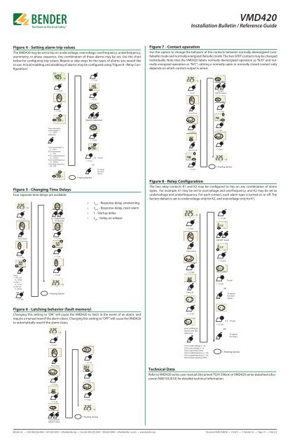
T MVMD420Installation Bulletin / Reference GuideFigure 4 - Setting alarm trip valuesThe VMD420 may be set to trip on undervoltage, overvoltage, overfrequency, underfrequency,asymmetry, or phase sequence. Any combination of these alarms may be set. Use the chartbelow for configuring trip values. Repeat or skip steps for the types of alarms you would liketo use. Actual enabling and disabling of alarms may be configured using “Figure 8 - Relay Configuration.”Figure 7 - Contact operationUse this option to change the behavior of the contacts between normally deenergized (nonfailsafe)mode and normally energized (failsafe) mode. The two SPDT contacts may be changedindividually. Note that the VMD420 labels normally deenergized operation as “N/O” and normallyenergized operation as “N/C”; utilzing a normally open or normally closed contact onlydepends on which contact output is wired.< 1.5 sec> 1.5 sec> 1.5 secT RFailsafeON/OFF Select< 1.5 sec< 1.5 secRPress Once< 1.5 secT RSetpoint AdjustmentPress nothing forundervoltage ( 1.5 sec< 1.5 secR1x for overvoltage (>)6 ... 300 V3x for asymmetry5 ... 30%4x for underfrequency10 ... 500 Hz5x for underfrequency10 ... 500 Hz7x for phase sequenceON / OFFx 2 To quit> 1.5 secRORTo repeatfor morealarmsRPress Once< 1.5 sec> 1.5 sec= Flashing SymbolFigure 5 - Changing Time DelaysFour separate time delays are available:> 1.5 secTRton1 Adjustment0...10 seconds= Flashing Symbol• t on1- Response delay, prewarning• t on2- Response delay, main alarm• t - Startup delay• t off- Delay on releaseFigure 8 - Relay ConfigurationThe two relay contacts K1 and K2 may be configured to trip on any combination of alarmtypes. For example, K1 may be set to overvoltage and overfrequency, and K2 may be set toundervoltage and underfrequency. For each contact, each alarm type is turned on or off. Thefactory default is set to undervoltage only for K2, and overvoltage only for K1.< 1.5 sec> 1.5 secRPress Twice< 1.5 secT RON/OFF SelectRPress Once< 1.5 sec> 1.5 sec< 1.5 secRPress:1 x for ton22 x for t0...10 sec3 x for toff0...99 secOR< 1.5 sec> 1.5 sec= Flashing Symbol< 1.5 secRPress 3x> 1.5 secRORTo quitTo repeatfor morealarmsFigure 6 - Latching behavior (fault memory)Changing this setting to “ON” will cause the VMD420 to latch in the event of an alarm, andrequire a manual reset if the alarm clears. Changing this setting to “OFF” will cause the VMD420to automatically reset if the alarm clears.> 1.5 sec< 1.5 secPress nothing forDevice error (Err)otherwise:R1x for undervoltage (< U)2x for overvoltage (> U)3x for asymmetry (Asy)4x for underfrequency (< Hz)5x for underfrequency (> Hz)6x for phase sequence (Phs)x 2 To quit> 1.5 secRORTo repeatfor relay 2= Flashing SymbolRPress Once< 1.5 sec< 1.5 sec> 1.5 secTechnical DataRefer to VMD420 series user manual (document TGH1396en) or VMD420 series datasheet (documentNAE1032010) for detailed technical information.< 1.5 sec> 1.5 secT RFault MemoryON/OFF Select= Flashing Symbol<strong>Bender</strong> Inc. • USA: 800.356.4266 / 610.383.9200 / info@bender.org • Canada: 800.243.2438 / 905.602.9990 / info@bender-ca.com • www.bender.orgDocument NAE1038020 • 10.2012 • © <strong>Bender</strong> Inc. • Page 1/1 • Side 2/2


