

Download - Bender
Download - Bender
Download - Bender

You also want an ePaper? Increase the reach of your titles
YUMPU automatically turns print PDFs into web optimized ePapers that Google loves.
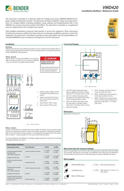
T MVMD420Installation Bulletin / Reference GuideThis document is intended as a reference guide for installing and using a BENDER VMD420 threephasevoltage and frequency monitor. This document includes installation, setup, and usage instructions.For complete details, including installation, setup, settings, and troubleshooting, refer to theVMD420 user manual, document number TGH1396en. This document is intended as a supplementand not a replacement to the complete user manual.Only qualified maintenance personnel shall operate or service this equipment. These instructionsshould not be viewed as sufficient for those who are not otherwise qualified to operate or service thisequipment. This document is intended to provide accurate information only. No responsibility is assumedby BENDER for any consequences arising from use of this document.InstallationFront Panel DisplayMountingVMD420 series devices may be DIN rail mounted, or screw mounted using the black clips locatedon the top and bottom of the device. Screw mounting requires an extra black clip (articlenumber B98060008, sold separately).1 2 3Wiring - GeneralRefer to figure 1 for wiring the VMD420. Use minimumAWG 24, maximum AWG 12 size wire. Refer to VMD420series user manual for complete technical details.! DANGERHAZARD OF ELECTRIC SHOCK,EXPLOSION, OR ARC FLASH• Disconnect all power before servicing.• Observe all local, state, and nationalcodes, standards, and regulations.425 6 71Figure 2 - VMD420 front display1. External supply voltage; 5A fuserequired for internal device protection2. System connections (N connectionis only necessary when N isbeing used)3. Alarm relay K1: SPDT contact4. Alarm relay K2: SPDT contact1. LED “ON” (green): Illuminates whenpower is applied to the device. Flasheswhen the CT connection alarm is active.2. LED “AL1” (yellow): Illuminates whenthe prealarm is activated. Flashes whenthe CT connection alarm is active.3. LED “AL2” (yellow): Illuminates whenthe main alarm is activated. Flasheswhen the CT connection alarm is active.5. TEST / UP button: Activates self-test /scrolls up inside main menu.6. RESET / DOWN button: Resets device /scrolls down inside main menu.7. MENU / ENTER button: Activates mainmenu / Confirms (momuntary push) orgoes back a step (held > 1.5 s) insidemain menu.4. Backlit LCD display3DimensionsDimensions in inches (mm).42.78”(70.5)1.87”(47.5)1.42” (36)Figure 1 - VMD420 wiring diagram1.22” (31.1)Wiring - ContactsUsing a normally closed or normally open contact utilizes two factors: wiring out of the properterminal, and setting the respective contact to normally energized or deenergized operation.Refer to the chart below for relay conditions. For changing the energized state of the contact,refer to “Figure 7 - Contact operation” on the reverse side of this document.The factory default for the VMD420 is normally energized operation for relay K2, and normallydeenergized operation for relay K1.2.66” (67.5)1.77” (45)3.54” (90)Device Relay ConditionsRelay Operation Setting Device Alarm State K1 STATE K2 STATENormally deenergized mode (N/D)Non-failsafe mode“N/O” in device settings menuEnergized in the alarm stateRelay will switch when the alarm isactivated.Normally energized mode (N/E)Failsafe mode“N/C” in device settings menuEnergized in the normal stateRelay will switch when the alarm isactivated, or when supply voltageto the device is lost.Power ON, normal state (no alarms)Power OFFPower ON, alarm statePower ON, normal state (no alarms)Power OFFPower ON, alarm state11-12 CLOSED11-14 OPEN11-12 CLOSED11-14 OPEN11-12 OPEN11-14 CLOSED11-12 OPEN11-14 CLOSED11-12 CLOSED11-14 OPEN11-12 CLOSED11-14 OPEN21-22 CLOSED21-24 OPEN21-22 CLOSED21-24 OPEN21-22 OPEN21-24 CLOSED21-22 OPEN21-24 CLOSED21-22 CLOSED21-24 OPEN21-22 CLOSED21-24 OPENMenu Flow Chart for Common SettingsFigure 4 through figure 8 on the reverse side of this document contain flow charts for modifyingcommonly used features and settings in the VMD420’s main menu. Not all available featuresare listed in this document. For more information, consult the VMD420 user manual.Menu LegendRTDOWN ARROW buttonUP ARROW buttonMENU / ENTER button< 1.5 s> 1.5 sMomuntary button pushHold button for at least 1.5 s,then release<strong>Bender</strong> Inc. • USA: 800.356.4266 / 610.383.9200 / info@bender.org • Canada: 800.243.2438 / 905.602.9990 / info@bender-ca.com • www.bender.orgDocument NAE1038020 • 10.2012 • © <strong>Bender</strong> Inc. • Page 1/1 • Side 1/2
T MVMD420Installation Bulletin / Reference GuideFigure 4 - Setting alarm trip valuesThe VMD420 may be set to trip on undervoltage, overvoltage, overfrequency, underfrequency,asymmetry, or phase sequence. Any combination of these alarms may be set. Use the chartbelow for configuring trip values. Repeat or skip steps for the types of alarms you would liketo use. Actual enabling and disabling of alarms may be configured using “Figure 8 - Relay Configuration.”Figure 7 - Contact operationUse this option to change the behavior of the contacts between normally deenergized (nonfailsafe)mode and normally energized (failsafe) mode. The two SPDT contacts may be changedindividually. Note that the VMD420 labels normally deenergized operation as “N/O” and normallyenergized operation as “N/C”; utilzing a normally open or normally closed contact onlydepends on which contact output is wired.< 1.5 sec> 1.5 sec> 1.5 secT RFailsafeON/OFF Select< 1.5 sec< 1.5 secRPress Once< 1.5 secT RSetpoint AdjustmentPress nothing forundervoltage ( 1.5 sec< 1.5 secR1x for overvoltage (>)6 ... 300 V3x for asymmetry5 ... 30%4x for underfrequency10 ... 500 Hz5x for underfrequency10 ... 500 Hz7x for phase sequenceON / OFFx 2 To quit> 1.5 secRORTo repeatfor morealarmsRPress Once< 1.5 sec> 1.5 sec= Flashing SymbolFigure 5 - Changing Time DelaysFour separate time delays are available:> 1.5 secTRton1 Adjustment0...10 seconds= Flashing Symbol• t on1- Response delay, prewarning• t on2- Response delay, main alarm• t - Startup delay• t off- Delay on releaseFigure 8 - Relay ConfigurationThe two relay contacts K1 and K2 may be configured to trip on any combination of alarmtypes. For example, K1 may be set to overvoltage and overfrequency, and K2 may be set toundervoltage and underfrequency. For each contact, each alarm type is turned on or off. Thefactory default is set to undervoltage only for K2, and overvoltage only for K1.< 1.5 sec> 1.5 secRPress Twice< 1.5 secT RON/OFF SelectRPress Once< 1.5 sec> 1.5 sec< 1.5 secRPress:1 x for ton22 x for t0...10 sec3 x for toff0...99 secOR< 1.5 sec> 1.5 sec= Flashing Symbol< 1.5 secRPress 3x> 1.5 secRORTo quitTo repeatfor morealarmsFigure 6 - Latching behavior (fault memory)Changing this setting to “ON” will cause the VMD420 to latch in the event of an alarm, andrequire a manual reset if the alarm clears. Changing this setting to “OFF” will cause the VMD420to automatically reset if the alarm clears.> 1.5 sec< 1.5 secPress nothing forDevice error (Err)otherwise:R1x for undervoltage (< U)2x for overvoltage (> U)3x for asymmetry (Asy)4x for underfrequency (< Hz)5x for underfrequency (> Hz)6x for phase sequence (Phs)x 2 To quit> 1.5 secRORTo repeatfor relay 2= Flashing SymbolRPress Once< 1.5 sec< 1.5 sec> 1.5 secTechnical DataRefer to VMD420 series user manual (document TGH1396en) or VMD420 series datasheet (documentNAE1032010) for detailed technical information.< 1.5 sec> 1.5 secT RFault MemoryON/OFF Select= Flashing Symbol<strong>Bender</strong> Inc. • USA: 800.356.4266 / 610.383.9200 / info@bender.org • Canada: 800.243.2438 / 905.602.9990 / info@bender-ca.com • www.bender.orgDocument NAE1038020 • 10.2012 • © <strong>Bender</strong> Inc. • Page 1/1 • Side 2/2


