TopScan G3 - Koning & Hartman
TopScan G3 - Koning & Hartman
TopScan G3 - Koning & Hartman

Create successful ePaper yourself
Turn your PDF publications into a flip-book with our unique Google optimized e-Paper software.
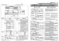
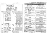
EN ISO9001Qualityinternationallevel<strong>TopScan</strong> <strong>G3</strong>Operating Instructions1 Safety instructions2.4 Selecting the detection areaPresence detector forautomatic pedestrian swing doorsThe unit may only be operated from a protection low-voltage systemwith electrical separation. The unit may only be opened and repairedby your supplier! Never touch any electronic or optical componentsof the sensor.Protect the sensor against rain and do not install it in the vicinity offluorescent lamps.2 Preparation / Installation2.1 Opening the housing5253631leftright4Depending on the door handing, the detection area has to be choosen(right/left). Standard setting is on the right side.6123456Aluminium housing (profile)Sensor (AIR 16 re)End cap 2 xFront coverMounting brackets 2 xPhillips head screws 2 x2.2 Removing the sensorRemove the end cap by loosening the screws.Remove the front cover.Note:Depending on the application, it will be necessaryto remove either the left or right end cap.FrontSet the beam direction on the backside of the sensor. To do so, slide thetransmitter to position L or R.Back2.5 Selecting the switching and operating modesPosition of the detection areaL = LeftR = RightOption 1:Release the red screws on both mounting brackets and then slide them to the side.Option 2:Release the red screws. Then slide the bracket holders together with the sensorcarefully out of the aluminium housing.2.3 Mounting the housing1 21 2Switch 1 Switch 2Operating mode moving or stationaryMoving mode: Switch 1 up– no background necessary, floor is ignored (background suppression)– the sensor cannot be tested in this operating mode (test input TI withoutfunction)Stationary mode: Switch 1 down (not recommended on a moving door)– a stable background is essential, the floor is analysed (background evaluation)– the sensor can be tested via the test inputMount the aluminium housing on the swing door.1 21 2Switching mode active/passive variablePassive variable: Switch 2 up– on detection, the relay switches from common to nc (see chapter 2.6)– this setting has the advantage that a power failure or wire damage is interpretedas a detection and will trigger the respective safety feature of the doorActive switching: Switch 2 down– on detection, the relay switches from common to no (see chapter 2.6)