TopScan G3 - Koning & Hartman
TopScan G3 - Koning & Hartman
TopScan G3 - Koning & Hartman

Create successful ePaper yourself
Turn your PDF publications into a flip-book with our unique Google optimized e-Paper software.
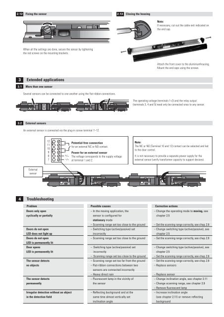
2.12 Fixing the sensor2.13 Closing the housingNote:If necessary, cut out the cable exit indicated onthe end cap.When all the settings are done, secure the sensor by tighteningthe red screws on the mounting brackets.Attach the front cover to the aluminiumhousing.Mount the end caps using the screws.3 Extended applications3.1 More than one sensorSeveral sensors can be connected to one another using the flat-ribbon connections.The operating voltage (terminals 1+2) and the relay output(terminals 3, 4 and 5) need only be connected once to any sensor.3.2 External sensorsAn external sensor is connected via the plug-in screw terminal 7–12.121110987+⁄~–⁄~Potential-free connectionfor an external NC or NO contact.Power for an external sensorThe voltage corresponds to the supply voltageat terminal 1 and 2.Note:The NC or NO (Terminal 10 and 12) contact can be selected and ledto the door control.It is not necessary to provide a separate power supply for theexternal sensor (verify transformer capacity to support devices).Externalsensor4 TroubleshootingProblem Possible causes Corrective actionsDoors only opencyclically or partiallyDoors do not openLED does not light upDoors do not openLED is permanently litDoor opensLED is permanently litThe sensor detectsno objectsThe sensor detectspermanentlyIrregular detection without an objectin the detection field– In the moving application, thesensor is configured forstationary mode– Scanning range set too close to the ground– Switching type (active/passive) setincorrectly– Scanning range set too close to the ground– Switching type (active/passive) setincorrectly– Scanning range set too close to the ground– Scanning range set too far from the ground– Flat-ribbon connections between twosensors are connected incorrectly– Heavy direct rain– Fluorescent lamp in the vicinity ofthe sensor– Reflecting background and at thesame time almost vertically setinclination angle– Change the operating mode to moving, seechapter 2.5– Set the scanning range correctly, see chap. 2.9– Change switching type (active/passive), seechapter 2.5– Set the scanning range correctly, see chap. 2.9– Change switching type (active/passive), seechapter 2.5– Set the scanning range correctly, see chap. 2.9– Set the scanning range correctly, see chap. 2.9– Replace sensors– Replace sensor– Change inclination angle, see chapter 2.11– Change scanning range, see chapter 2.9– Remove fluorescent lamp– Increase inclination angle(see chapter 2.11) or remove reflectingbackground