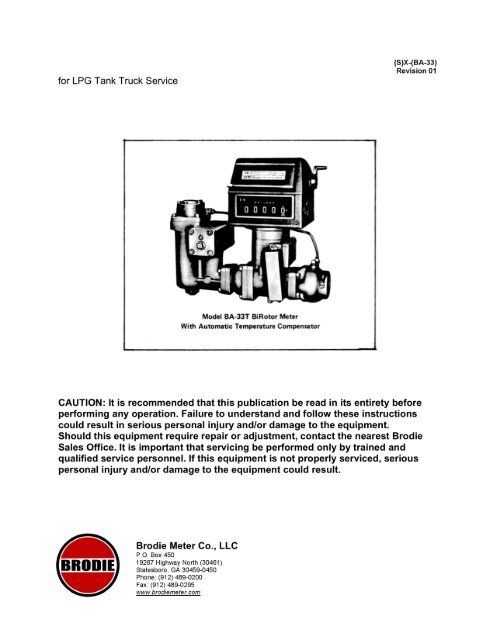
Model B33 Manual - Brodie International
Model B33 Manual - Brodie International
Model B33 Manual - Brodie International

You also want an ePaper? Increase the reach of your titles
YUMPU automatically turns print PDFs into web optimized ePapers that Google loves.
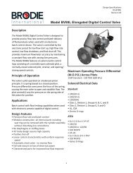
Materials of ConstructionBody and Housing: Ductile IronRotors : Aluminum with Nitralloy ShaftGears: Stainless SteelBushings: Carbon filled TeflonBall Bearings: Stainless SteelStrainer Screen: 80 Mesh Stainless Steel"0" Rings: Buna NDifferential Valve: Ductile IronRatingsComplies with NFPA No. 58 (ANSI Z106.1). Complies with ANSI 8167.1 (U.L. 25).Working pressure: Maximum of 350 P.S.I.G. (2413.2 kPa) Meets or exceeds hydrostaticpressure test of 1750 P.S.I. (12065.8 kPa) or five times the maximum working pressure.Operating Temperature: Maximum of 150°F (66°C) Minimum of -20°F (-29°C)PerformanceAccuracy and RepeatabilityMeets requirements as set forth in U. S. Bureau of Standards Handbook 44.Typical Accuracy CurveTemperature Compensator (<strong>Model</strong> BA-33T)Base temperature can be locked out for gross (uncompensated) proving of meter.For Anhydrous Ammonia, <strong>Model</strong> BA-33 (less red metal with Neoprene seals) andseparate Series 44110 Automatic Temperature compensator must be used. Forcomplete details on the Series 4400 ATC reference Design Specification IS) DS-4400.Connections1-1/2" or 2" NPT. Two (2) Inlet connections to facilitate ease of installation.
CapacitiesTypical Pressure Drop CurveShipping Weight and VolumeShipping dimensions and cube (approximate) with Veeder-Root printer counter.Dimension and cube shown are for domestic pack in cardboard carton. Export pack willbe slightly smaller.WEIGHT- Approximate -With LOB Printing Counter
Figure 2.1, Table 2.1 Dimensions (For Certified Dimension prints, ConsultFactory)
Section 2 Installation2.1 GeneralThis section contains the procedures for receipt and installation of the meter. Specificinstructions are provided for accessory equipment.2.2 Receipt of EquipmentWhen the equipment is received, the outside of the packing case should be checked forany damage incurred during shipment. If the packing case is damaged, the local carriershould be notified at once regarding his liability.A report should be submitted to the Product Service Department, <strong>Brodie</strong> Meter Co., LLCDivision, Statesboro, Georgia 30459.Remove the envelope containing the packing list. Carefully remove the equipment fromthe packing case. Make sure spare, or replacement parts are not discarded with thepacking material. Inspect for damaged or missing parts.In many cases the accessory items that form the "Stack-up" of the meter have beenshipped as a complete unit where possible. If not, it will be broken apart into as fewassemblies as is practical. Refer to the Packing List for information as to what issupplied for your particular meter. In the event that any items are missing from yourshipment, contact your local <strong>Brodie</strong> Representative or Sales Office and provide themwith the <strong>Brodie</strong> Sales Order Number.2.3 Return ShipmentTo be able to process returned goods quickly and efficiently, it is IMPORTANT that youprovide essential information. Do no return any assembly or part without an "R. M. R."(Returned Materials Report) or a letter which describes the problem, corrective action (ifany) and the work that is to be performed at the factory. "R.M.R." forms can be obtainedfrom <strong>Brodie</strong> District Sales Offices or the Service Department, <strong>Brodie</strong> Meter Co., LLC,Highway 301 North, Statesboro, Georgia 30458.Place a copy of either of the above inside the shipping container and attach it physicallyto the material being returnee. A copy of your packing list should be placed inside thecontainer.Failure to follow the above procedure could result in considerable delay because itemshave not been properly identified.2.4 Recommended ProceduresPrior to installation of the meter, the following items of general information andrecommendations should be considered:
1. On new installations, the lines should be flushed thoroughly to rid the pipe ofwelding bead, pipe sca7. etc. before the meter is placed in service. This can bedone by using a spool-piece in place of the meter.2. It is recommended that the meter be mounted in a position that will allowsufficient clearance for removal of the strainer screen and the float assembly,from the air eliminator/strainer.3. Install a strainer ahead of the inlet of the meter.4. The meter should be level for proper and specified of operation. The rotors in themeasuring element must be in horizontal position.5. Shut-off or control valves should be located downstream, of the meter.6. Installation should be in accord with the proper local standards and regulations,such as API standards 1101 and NBS Handbook H-44.7. Block valves should be located upstream and down stream of the meter.
Section 3 OperationCaution: Do Not Operate This Meter In Excess Of Values Listed In Section 1.6,Specifications.3.1 General1. When the meter is first put into operation, or at any time the meter has beendrained, it should be started slowly until all air has been exhausted from the outerhousing.2. To prevent high shock pressure or surges, care should be exercised in openingor closing valves when starting or stopping flow through the meter.3. On new installations, the lines should be flushed thoroughly to rid the pipe ofwelding bead, pipe scale, etc. before the meter is placed in service. This can bedone by using a spool-piece in place of the meter.Note: Failure To Perform The Above Procedures Could Result In Serious DamageTo The Meter.Water should NEVER be used as a flushing medium through this meter. Always use aflushing medium that is compatible with the metallurgy of the meter and its internalparts, and similar to the product for which this meter was intended. See Materials ofConstruction, Section 1.6. Failure to comply with these proper operational procedureswill void the warranty.3.2 Operation - Meter Register and PrinterCaution: Do Not Turn Printer/Reset Handle Counter Clockwise.Do not start delivery unless shutter is in full open position. If numerals on indicatingwheels are not in full view, resetting operation has not been completed, in which case,turn reset knob until shutter disappears and reset knob returns to its normal position.1. Lift ticket slot cover and insert ticket as far as it will go, FACE DOWN ANDBOTTOM END FIRST. If ticket does not enter tray, turn crank one completerevolution, or until it reaches positive stop. This will lift sealing pin and permitinsertion of ticket.2. When ticket is in place, make one complete turn in a clockwise direction untilpositive stop is reached, leaving handle in down position. Mechanism is now setfor delivery.3. After completing delivery, turn crank one complete revolution in clockwisedirection until positive stop is reached, release handle and withdraw ticket.Important: All Turns Must Be Full To Internal Stop. Keep Crank In Straight DownPosition At Finish. Keep Ticket Slot Cover Closed When Not In Use. This WillPrevent Excessive Dirt From Entering The Printer Mechanism.
Section 4 Maintenance4.1 GeneralThe amount of maintenance necessary for efficient meter performance depends uponsuch factors as –1. Continuity of Operation - A meter which operates almost continuously, obviouslywill require more attention than one on intermittent duty.2. Rate of Flow - The practical life of any piece of equipment is proportional to itsspeed of operation. A meter operating at, or close to its maximum rating willnaturally have a shorter life than operating at a reduced rate.3. Cleanliness of Product - Abrasive solid matter accelerates meter wear.Meters that are given even a little attention regularly will deliver better performance andhave a longer life than those that are given no attention until they have failed.Frequently a meter's performance will depend, to a considerable extent upon the properfunctioning of the accessory equipment in the piping system. Following are listed someof the conditions and factors influencing meter performance.A meter should be kept filled with the liquid it is measuring. Draining results in theformation of deposits and gums which increase the mechanical friction.Any leaky shut-off valves or check valves which would permit the meter to drain shouldbe repaired or replaced.The meter should be kept free of water. Usually, regular inspection and draining ofstorage tanks is sufficient protection.A regular procedure should be set up to clean the strainer basket to prevent it fromfilling and rupturing the screen.The valves and operating mechanism of an air eliminator should be given occasionalinspection.The counter of a meter should be given some protection during extreme weatherconditions.A meter taken out of service for any length of time should,: be protected and sealedagainst entry of foreign material:: and corrosion.Caution: Before Performing Any Disassembly Or Reassembly Procedures AllFlow To Meter Should Be Off. All Electrical Connections To Accessories ShouldBe Disconnected. Service Should Be Performed By Trained And QualifiedPersonnel Only.4.2 General Disassembly ProcedureComponents of this meter and sub-assemblies are relatively small. Therefore, it issuggested that a clean, neat work area be selected before attempting any service toavoid loss and/or damage of parts.
It is recommended that the entire assembly, including the meter, strainer/air eliminator,and valve be removed from the tank truck before attempting to service the meter itself.Note: The Meter Body Must Be Disconnected From The Mounting Platform IfMaintenance Is Required Only On The Measuring Unit Assembly.Before attempting to disassemble or remove the assembly, close block valves on inletand outlet of meter.Caution: Bleed Off The Remaining Pressure In The Meter Slowly But CompletelyBy Slightly Loosening All Pipe Fittings. All Pressure Must Be Bled Off BeforeAttempting To Complete Disconnections In Order To Prevent Personal Injury.Loosen the pipe unions on the inlet and outlet of meter, and remove the screws holdingthe meter base to tank truck to remove the entire assembly.4.3 General Reassembly ProcedureA. CleaningPrior to reassembly, all parts should be thoroughly washed in solvent, light fuel oil orkerosene to remove any contamination, and dried with compressed air and/or clean,lint-free wipers.B. 0-ringsPrior to reassembly, carefully inspect all 0-rings for cuts, nicks, or deformation. Use new0-rings for replacement as necessary.Lubricate all 0-rings sparingly with light oil to aid in holding 0-rings in place and toprovide lubrication for O-rings during reassembly.Good practice is to always replace 0-rings with new ones during reassembly.C. BearingsInspect bearing for cleanliness and looseness. Excessive wear dictates the need forbearing replacement.If old bearings are reused for reassembly, they should be lubricated sparingly with lightoil before replacing in meter.4.4 Meter Measuring UnitA. Removal/DisassemblyReference to Figures 4.1, 6.1, and 6.2.1. Separate Input end case (Item 1) and output end case (Item 10) by removing thefour socket head cap screws (Item 2). Remove 0-ring (Item 5) and put in a safeplace to avoid cutting or nicking2. Remove Measuring Unit (Item 4) and block rotors (Items 46 or 37) by inserting aplastic rod through opening in the end plate as illustrated in Figure 4-1.Caution: Extreme Care Must Be Exercised When The Measuring Element IsExposed Or Handled. Hands Must Be Kept Clear Of The Timing Gears, Rotors
And Measuring Chamber Or Serious Personal Injuries Can Occur. Due To ThePrecision Balance Of The Rotors And Timing Gears, They Can Be Set In MotionEasily. Keep Hands Clear Of These Parts At All Times. At No Time Should TheHands Be Used To Brace These Parts While Servicing.3. Remove locknuts (Item 52) from each rotor shaft.4. Remove timing gears, small gear (Item 53) on 3-tooth rotor and large gear (Item49) on 4-tooth rotor by tapping the gears lightly on the flat face with a plastic orrubber mallet. Remove spacer (Item 54),Caution: Avoid Hitting The Teeth Of The Gears. The Center H. Of Each TimingTear Is A Tapered Bore Which Fits The Tapered End Of The Rotor Shafts. TappingThe Gears Will Break The "Taper Lock" And Release The Gears From The RotorShafts.5. Remove three socket head screws (Item 55) holding the rear end plate (Item 38),but do not remove end plate at this time.6. Remove worm (item 40) by removing screw (item 41) and lock washer (item 42).To disassemble worm shaft (item 45), remove roll pin (item 43).7. Remove screw (item 58), washer (item 42), shim (items 44 and/or 48) and spacer(item 50).8. Remove three socket head screw (item 55) holding the front end plate (item 38).NOTE: Lightly Tap, With A Plastic Mallet, The End Of The Two Rotor Shafts ToLoosen The End Plate. Mark The End Plate As To Which End Of The Body It IsDisassemble. Both End Plates Are Identical Except For The Dowel Holes.9. Remove the end plate (item 38), lift out rotors (items 37 and 46) from the meterbody (item 47).10. To remove rear end plate (item 38), tap from inside of meter body with woodenhandle of mallet.NOTE: Dowel Pins (Item 56), Two On Each End Of Meter Body Should Remain InMeter Body When The Front And Rear End Plates Are Removed. Occasionally,The Dowel Pins Will Come Off In End Plates. This Is Acceptable As Long AsDowel Pins Are Retained For End Plate Location Upon Reassembly. Mark TheEnd Plate As To Which End Of The Body It Is Disassemble.11. Ball bearings (item 39) can be removed from the end plates (item 38) by gentlytapping or pressing on the inner raceway of the bearings from inside covers.B. CleaningRemoving all corrosion and accumulation from the rotors, meter body, and end plates.
CAUTION: Extreme Care Must Be Taken When Cleaning To Insure That RotorsAnd Meter Body Parts Are Not Altered Or Damaged In Any Way. If The Rotors OrMeter Body Are Scored Or Galled, Remove The High Spots With A File OrScraper. Crocus Cloth May Be Used For Polishing. Wash All Parts Thoroughly InSolvent, Light Fuel Oil, Or Kerosene.C. Reassembly/InstallationReference Figure 6.1 and 6.2NOTE: Two Blocks Of Wood About 2" By 2" Or The Equivalent Will Greatly AssistAssembly Procedure As Illustrated In Figure 4-1. Figure 4-1 Proper Method ForBlocking Rotors For Measuring Unit Disassembly1. Align the port openings of the front end plate (item 47) using care to align the twolocating dowel pins (item 56) with their corresponding holes. Secure the front endplate to meter body by tapping it down with a soft mallet, alternating from oneside to the other, and installing the three socket head screws (item 55).CAUTION: Do Not Drop Or Damage Rotors.2. Install the two rotors (items 37 and 46) so that the threaded, tapered rotor shaftsprotrude from the front end of the meter body.3. Attach the rear end plate (item 38) to the meter body (item 47) using care to alignthe two locating dowel pins (item 56) with their corresponding holes. Secure therear end plate alternate tapping method and installing the three socket headscrews (item 55).4. Install bearings (item 39) over end of rotor shafts into bearing bore provided infront and rear end plates. Use a sleeve or deep socket with an outside diameterslightly less than that of the bearing outer race to press or tap the bearings intobearing bores until securely seated. Use care to drive bearing straight down andmake certain that no foreign materials enter the bearing.5. Secure bearings in place by installing spacer (item 50), shims (item 44 and/or48), washer (item 42) and screw (item 58).NOTE: Use Shims (Item 44 And/Or 48) Until A .005 Clearance Is Achieved BetweenEnd Plate And 4 Tooth Rotor.6. Install worm shaft (item 45) on the 3 tooth rotor and secure with roll pin (item 43).7. Install shims (item 44 and/or 48), worm (item 40), washer (item 42) and screw(item 41).NOTE: Use Shims (Item 44 And/Or 48) Until A .005 Clearance Is Achieved BetweenEnd Plate And 3 Tooth Rotor.
8. Place spacers (item 54) on the threaded shaft of each rotor (item 37 and 46).9. Loosen the (3) screws on the large timing gear assembly (item 49) and slide thegear hub plate. Tighten screws and place the large timing gear assembly (item49) on the threaded shaft of the four tooth rotor (item 46). Figure 4-2 ProperMethod for Timing Place the small timing gear (item 53) on the threaded shaft ofthe three tooth rotor (item 37).NOTE: If New Set Screws (Item 51) Has To Be Replaced, Install From The BackSide Of Each Timing Gear. The Set Screws Must Align With The Holes In TheSpacers (Item 54).10. Attach locknuts (item 52) to the threaded rotor shafts and tighten.11. Tighten set screws (item 51) in each timing gear alternating from one side to theother on each gear until the gears spin freely.12. Timing Rotors - With feeler gauges (begin with size .003 or .004) carefullycentralize the lobe of the three-lobe rotor in a flute of the four-flute rotor. Thismay be done through the openings in the measuring element. The rotors mustturn freely and must not contact each other.
Figure 4.3 Proper Method for Setting Rotor End ClearanceTo properly time rotors, using the feeler gauges inserted between rotors, tighten locknut(item 52). Check clearance at several points between rotors. Remove gauge and spinrotors.If there is contact between rotors or rotors do not turn freely recheck clearances atseveral points and if necessary repeat timing procedure until desired freeness isobtained.13. Install measuring unit (item 4) (Figure 6-1) into the output end case (item 10).NOTE: Dowel In The Measuring Unit Must Align With The Hole In The Top Of TheOutput End Case (Item 10). The Meter Will Run Backward If Measuring UnitAligned With Wrong Hole.14. Install 0-Ring (Item 5) in groove on the output end case (item 10). Place inputend case (item 1) in position on output end case (item 10). Secure together byinstalling screw (item 2), and washers (item 3).15. Install O-Ring (Item 9) in groove on top side of the meter.16. Install Counter Base Plate Assembly (item 7), secure with screws (item 6).NOTE: The Gear On The Counter Base Plate Assembly (Item 7) Must Mate WithThe Worm Wheel (Item 40) On The Measuring Unit.4.5 Automatic Temperature Compensator (ATC) - <strong>Model</strong> BA-33TA. Principle of OperationRefer to Figure 4.4. The temperature compensator is made up of thermal productbellows, linkage plate assembly, ATC control gear train, and 600 lockout incorporatedinto the linkage plate assembly by means of a movable pivot pin.The bellows is mounted in the front cover of the meter, immersed in liquid beingmetered.Product temperature variations cause linear expansion and contraction of the bellowswith respect to product temperature. Bellows expansion and contraction is transferred tothe ATI' gear train by means of linkage lever (4) and push rods (3 & 5) to change theposition of the friction roller (6) on the platform gear (7), providing compensated readouton the meter counter.
The compound input gear (8), through the compound idler gear (9), drives the planetarm assembly (10) and the hardened, polished steel platform gear (7).The platform gear drives the worm gear (14) through the friction roller. The worm geardrives the worm wheel and spur gear assembly (13) which, in turn, drives the externalteeth of the planetary ring gear (17) through an idler gear (15). The internal teeth of thering gear drive four planetary gears which transmit compensated output to the registerdrive gearing.The infinitely variable transmission of the friction drive acts as a counter-directionalforce subtracting from the ATC output rather than adding to the output or driving theplanetary system. Thus the compensating mechanism is not required to carry any of thetorque load of the counter equipment and is not subject to slippage under heavy loads.The speed of the friction roller is determined by its position on the platform gear and itsspeed varies, as does the speed of the ATC output. The position of the roller on theplatform gear is controlled by the product bellows movement as it expands or contractsdue to product temperature change.For normal ATC operation, with register readout compensated for product temperaturevariations, the movable pivot pin is located in position (B).The temperature compensator can be "locked out" (made inoperative) by placing themovable pivot pin in position (A). Output from the automatic temperature compensatorthen becomes gross uncompensated indication.B. Removal (Reference Figure 6.1)Remove ATC adjustment cover (item 29) by removing two screws (Item 31). Removelinkage plate assembly (item 27) by removing three screws (item 30). Remove bellowsshaft (item 32) by withdrawing it from the bellows cover (item 33). Remove adjustmentshaft (item 26) by withdrawing it from the counter base plate assembly housing (item76).Please note rounded ends of bellows shaft and protruding flat end of adjustment shaftfor purposes of reassembly. Remove bellows cover (item 33) by removing 3 sockethead screws (item 28), and withdraw bellows (item 35). Use caution not to dent bellows.Remove O-Ring (item 34) and put in safe place.
Remove the two machine screws (item 20), and the two hex head screws (item 19) withlock washers (item 18). Lift the ATC Rear assembly (item 21) from the counter baseplate assembly (item 16). Please note that the ATC gear assembly is held in position oncounter base plate assembly by locating dowel pins (item 36). Coupling (item 17) cannow be lifted off of drive shaft.C. Maintenance (Reference Figure 6.1)In normal use, no service is required other than periodic lubrication.If the gear assembly of the ATC (item 21) is found to be damaged, worn, or otherwiseunserviceable, an exchange replacement assembly should be ordered from the nearest<strong>Brodie</strong> Regional Office.D. Lubrication (Reference Figures 6.1 and 6.7)No lubrication is required on the linkage plate assembly (item 27), the bellows shaft(item 32), or the adjustment shaft (item 26).In order to achieve maximum service life, the ATC gear assembly (item 21) should beremoved and lightly lubricated at approximately six month intervals.Lubricants required are given in Table 4-1, and points of lubrication are shown onFigure 6-7.Lubrication should be done thoroughly but sparingly. Do not use excessive quantities oflubricant.E. Installation (Reference Figure 6.1)Place coupling (item 17) in position on packing shaft (item 61) in counter base plate(item 16).Place ATC gear assembly (item 21) in position on top of the counter base using care toassure that coupling (item 17) is properly aligned with input shaft on bottom of ATC gearassembly. When input shaft and coupling are properly engaged, the ATC gearassembly will be seated correctly inside the counter base plate housing. Thisengagement may be verified by temporarily operating the meter and checking forcorresponding ATC output.NOTE: Dowel pins (item 36) in the top of the counter base must align with thelocation holes on bottom of the ATC gear assembly.Secure the ATC Rear assembly (item 21) by replacing two machine screws (item 20)and two hex-head screws (item 19) with lock washers (item 18).Install 0-Ring (item 34) in outer part of bellows opening in output end case (item 10).Make certain bellows (item 35) is not dented or otherwise damaged, and reinstall intofront end cover bellows bore.Replace bellows cover (item 33) and secure by installing three socket head screws(item 28).
Replace bellows shaft (item 32) by inserting into hole in bellows cover.Replace ATC adjustment shaft (item 26) by inserting into bushing in the front of thecounter base plate, with square end out. Replace linkage plate assembly (item 27) andsecure with three screws (item 30).F. Butane Service (Reference Figure 4.4)The fixed pivot point for the linkage lever has been set (at the Factory) at the "P" or "B"position on the linkage plate, indicating propane or butane service respectively. If theproduct metered is changed from propane to butane (or vice versa), then the pivot pointmust be changed accordingly.To change the pivot point, simply remove the roll pin that attaches the linkage lever tothe linkage plate, and install it in the desired position for either propane or butaneservice. Changing the metered product and fixed pivot point necessitates recalibrationof the ATC.G. ATC Calibration Procedure (Ref. Figure 6.1 and 6.7)NOTE: Accuracy adjustments, for the model BA-33T meter, are inherent to andaccomplished within the calibration procedure for the Automatic TemperatureCompensator, eliminating the need for a separate accuracy Adjustersubassembly (such as the 4200 Adjuster used on the model BA-33 meter).The ATC is designed for use with propane or butane at a product temperature between- 10OF (-23oC) and +130oF (+54oC). The unit is calibrated for a base compensationtemperature of 60OF (15oC) and sealed with seal wire and lead seal before shipping. Ifrecalibration becomes necessary, a volumetric prover must be used in accordance withproper regulation, such as API Standard 1101.NOTE: Calibration procedure warrants breakage of the ATC seal. Propermeasurement and regulatory officials must be notified prior to seal breakage, andupon installation of new seal after calibration is completed.
To calibrate the ATC, first remove the two screws (item 31) so that the adjustment cover(item 29) may be removed. Note the location of the instruction decal inside theadjustment cover (See Figure 4-5). Referring to Figure 4-4, remove the pivot pin fromthe ATC operation position (B) on the linkage lever (4), and place it in the 60oF lockoutposition (A). Running a specific volume through the meter, at a product temperature of60oF, should result in a meter register readout equal to the quantity of liquid indicatedby the volumetric prover. Inserting a thermometer in the thermometer well (located inthe blind flange of the strainer/vapor release assembly) provides a means of monitoringproduct temperature. Proper temperature correction factors must be incorporated forproduct temperatures other than 60oF.If there is a discrepancy between meter readout and prover readout, adjustment isnecessary. Compensation for the present discrepancy can be accomplished by turningthe 60OF adjustment screw. Each adjustment division equals 0.157. Turning the screwin a clockwise direction will decrease counter readout, while counter-clockwiseadjustments increase counter readout. Several prover test r8ns are warranted to verifythe proper adjustment for the 60 F lockout position.Replace the pivot pin to the ATC operation position (B), on the linkage lever. Run asmall amount of volume through the meter (approximately 30 U.S. gallons), to allow theATC to compensate for the change in pivot pin position, before continuing with ATCcalibration procedure.Running a specific volume through the meter at a product temperature within theoperating range of the ATC should now result in a meter register readout corrected tothe 60OF volume. If there is a discrepancy between actual readout and calculatedreadout, adjustment is necessary. Compensation for the percent discrepancy can beaccomplished by turning the ATC adjustment screw. Each adjustment division equals0.3%. Turning the screw in a clockwise direction will decrease counter readout, whilecounter-clockwise adjustments increase counter readout. Several prover test runs arewarranted to verify the proper adjustment for the ATC operation position.NOTE: Any attempt to service the ATC assembly or linkage plate assembly mayresult in serious damage and/ or personal injury. Contact <strong>Brodie</strong> ServiceDepartment for information concerning ATC exchange policy.Once the Automatic Temperature Compensator has been proper] calibrated, replacethe Adjuster cover and secure with two screws.4.6 Series 4200 Adjuster - <strong>Model</strong> BA-33A. Removal (Reference Figure 6.1)Remove four screws (item 14) and lift off Adjuster (item 13) from top of counter baseplate assembly (item 7).If the Adjuster assembly is found to be damaged, worn, or otherwise unserviceable, anexchange replacement assembly should be ordered from the nearest <strong>Brodie</strong> RegionalOffice.
B. Installation (Reference Figure 6.1)Place Adjuster (item 13) in position carefully on top of counter base plate (item 7)making certain that coupling on bottom side of Adjuster is aligned properly with packingshaft (output from counter base plate).When packing shaft and coupling are properly engaged, the Adjuster will be correctlyseated on the counter base plate. This engagement may be verified by temporarilyoperating the meter and checking for corresponding Adjuster output. Secure Adjuster tocounter base plate by installing four screws (item 14).C. Accuracy AdjustmentThe BA-33 meter is adjusted for accuracy by changing the gear ratio between the meterpacking shaft and the counter until the counter registers the amount of liquid measured.The Adjuster accomplishes this change in positive and definite increments. The Adjusteris provided with two adjusting knobs (see Figure 4-6). One knob is used to make coarseadjustments; the other to make fine adjustments. To make an adjustment, lift lockingplate and push in or pull out on adjusting knob. Pushing the knobs into the Adjusterdecreases the counter readings, while pulling the knobs out will increase the readout.Each groove of the coarse adjustment equals .67, of the volume delivered, and eachfine adjustment groove equals .05%.4.7 Counter Base Plate Assembly(Reference Figures 6.1, 6.3, or 6.4)1. Lift off coupling (item 17) from counter base plate assembly (item 7) or ATChousing (item 16).2. Remove screw (item 6) and lift off counter base plate housing assembly (item 7)or ATC housing (item 16).3. Remove screws (item 67) and remove counter base plate housing (item 76) frominner gland bearing (item 65).
4. Remove retaining rings (item 59) and disassemble, using care not to damage0-Ring (item 64). Always replace this 0-Ring with a new one on reassembly.5. Remove 0-Ring (item 9) from the output end case (item 10) using care not todamage 0-Ring (item 9). Always replace this O-Ring with a new one onreassembly.B. Reassembly/Installation(Reference Figures 6.1, 6.3, or 6.4)1. Slide ball bearing (item 66) onto gear shaft (item 61).2. Install gear shaft (item 61) and ball bearing (item 66) into inner gland bearing(item 65).3. Place properly lubricated 0-Ring, (item 64) on gear shaft (item 61) and push intobore inside the inner gland bearing (item 65).4. Place bushing(item 63) and washer (item 62) in position on gear shaft assembly(item 61), secure with retainer ring (item 59).5. Attach the counter base plate housing (item 76) to the inner gland bearing (item65) with two screws (item 67).6. Install 0-Ring (item 9) in groove on top of the meter.7. Position counter base plate housing assembly (item 7) or ATC housing (item 16)onto meter and secure with screws (item 6)NOTE: The gear on the worm shaft assembly (item 61) must mate with the wormwheel (item 40) on the measuring unit.8. Replace coupling (item 17).4-8 Vapor Release/Strainer AssemblyA. Removal/DisassemblyRefer to Figure 6-1. Disconnect tubing, nut (item 77) and tubing (item 78) from elbow(item 80).Refer to Figure 6-5 and Table 6-2. Remove four socket head cap screws (item 7) and liftout complete head assembly including the float link assembly (item 3) and linkage guidebracket (item 6). Remove 0-Ring (item 17) and put in safe place to avoid nicking orcutting.Float shroud (item 2) can be removed from housing (item 1), if necessary, by lifting out.Remove five socket head cap screws (item 9) to allow removal of the vapor release cap(item 10).The float link assembly (item 3) can be separated by removal of cotter pins (item 4) andspacer (item 5). Use care not to dent float.Hold the poppet (item 14) by inserting a screwdriver shaft or small piece of bar stock incross slot in lower part of poppet. Remove jam nut (item 11), two diaphragm washers(item 12) and diaphragm (item 13). Lift out poppet. Place diaphragm in safe place.
The linkage guide bracket (item 6) can be removed as necessary by taking out fourscrews (item 16). Remove 0-Ring (item 15) and put in a safe place to avoid nicking orcutting.The float (item 23) can be disassembled from the float link assembly (item 3) byremoving cotter pin (item 24).To remove strainer (item 20) from housing, loosen and remove four socket head capscrews (item 7) to release blind flange (item 18). Insert fingers into inside of strainer andpull out. Remove 0-Ring (item 22) and put in safe place to avoid cutting or nicking.B. Reassembly/InstallationRefer to Figure 6.5 and Table 6.2. Carefully inspect the diaphragm (item 13) forcracking, peeling or flaking. Use new diaphragm for replacement if necessary.Inspect the poppet (item 14) for excessive wear on the three guide ribs that fit in thevapor release valve body and for wear of the pilot ball seat on bottom of poppet. Usenew poppet for replacement if necessary.Inspect all pivots of linkage for signs of excessive wear. Use new linkage parts andassemblies as necessary for replacement.Carefully inspect the strainer (item 20) inner screen for ruptures or signs of stretching ofthe mesh. If the inner screen is ruptured or stretched, the strainer assembly should bereplaced.Insert strainer (item 20) into housing and replace O-Ring (item 22). Replace blind flange(item 18) and reinstall and tighten four socket head cap screw (item 7). Refer to Figure6.5 and Table 6.2.If the linkage guide bracket (item 6) and 0-Ring (item 15) have been removed, replaceitem 6 and 15, and retain by reinstalling four screws (item 16).Insert poppet (item 14) into place in the vapor release valve body (item 8). Install onediaphragm washer (item 12) over threaded end of poppet. Install diaphragm (item 13)over threaded end of poppet. Install second diaphragm washer (item 12) over thethreaded end of poppet on top of diaphragm. Hold the poppet by means of ascrewdriver shaft or a piece of bar stock in the cross slot in lower end of poppet. Installand tighten jam nut (item 11) on threaded end of poppet. Refer to Figure 6.5 and Table6.2.If the float (item 23) has been removed, replace float on the float link assembly andretain with cotter pin (item 24).Replace float link assembly (item 3) including float, on the linkage guide bracket (item 6)by use of cotter pins (item 4) and spacer (item 5). Refer to detail A of Figure 6.5 forillustration of correct reassembly.Replace vapor release cap (item 10) using five socket head cap screws (item 9) (Referto Figure 6.7). Use caution to assure that holes in diaphragm (item 13) are properlyaligned before installing cap screw (item 9). The poppet should be lifted up until it seatsto allow socket head screws (item 9) to be easily inserted through the diaphragm.
If the float shroud (item 2) has been removed, reinstall the shroud in the housing (item1).The float link assembly (item 3) must move freely without binding or dragging of linkagefollowing reassembly.Lift float to seat the pilot ball and the poppet (item 14).Apply approximately 15 PSI air pressure to the vapor release opening in top of head.Proper seating of the poppet and pilot ball will be indicated by no flow of air.Release float - air flow should be evident.Repeat several times, lifting float to seat ball and poppet and releasing to assure theseating is reliable and consistent.Reinstall 0-Ring (item 17) in top of housing (item 1).Reinstall the float, float linkage, and head assembly into opening on top of housing andretain with four socket head cap screws (item 7) (Refer to Figure 6.5).Reconnect tubing (item 78) and tubing nut (item 77) to elbow (item 80), as illustrated inFigure 6.1.4-9 Differential Pressure Control ValveA. Removal/DisassemblyRefer to Figure 6.1. Disconnect tubing nut (item 77) and tubing (item 78) from connector(item 79) located on valve body.Remove the complete valve assembly from the front end cover by removing four nuts(item 73) and 0-Ring (item 74).Refer to Figure 6-6. Place valve assembly with 1 '1" NPT threaded end down on arborpress. Remove bushing (item 11,.Place sleeve slightly smaller in diameter than the inside diameter of the retaining ring(item 10) on face of retainer (item 9). Press with arbor press sufficiently hard enough toallow easy removal of the retainer (item 9). Use small screwdriver or scribe to push endof retainer out of groove in body and "peel out" retainer.Slowly release pressure from arbor press until all tension created by springs (item 3 and6) is released.CAUTION: Piston may be held in valve body by 0-Ring so that spring tension isnot fully released. Exercise care in making certain all spring tension is releasedin order to prevent personal injury.Remove retainer (item 9), 0-Ring (item 8), check valve (item 7), spring (item 6), piston(item 5) with O-Ring (item 4), and spring (item 3).
B. Reassembly/InstallationWith valve body positioned on arbor press, in the same position as used in disassembly,insert spring (item 3) into the valve body.Install properly lubricated O-Ring (item 4) in the 0-Ring groove of piston (item 5) andplace piston down over spring (item 3). Insert spring (item 6) into hole in nose of piston,insert check valve (item 7) down over spring (item 6).Place O-Ring (item 8) around rear shoulder of retainer (item 9), and place retainer overface of check valve with 0-Ring down.Using pressing sleeve on the face of the check valve lightly compress springs by handwhile positioning under arbor press. Retainer should be around pressing sleeve andloose at this time.When well centered, press piston (item 5), check valve (item 7), and retainer (item 9)down into bore of valve body with the arbor press.Use care to press in straight and carefully so as not to cut the position 0-Ring (item 4).When sufficiently compressed the retainer groove in the valve body will just show. Insertlower end of retainer into groove and complete insertion by working the rest of theretainer into the groove in a spiral direction. Make certain that the full length of theretainer including the outside end is in the groove - seated - before releasing pressurefrom the arbor press. Install 0-Ring (item 8) into groove on flanged end of valve body.Refer to Figure 6.1. Remove complete valve (item 70) with front end cover and securewith four nuts (item 73) (Refer to Table 6.1). Reconnect tubing (item 78) by positioningand tightening the tubing nut (item 77) on connection (item 79) on side of valve body.
Section 5 TROUBLESHOOTING5-1 GeneralTable 5.1 has been provided to aid in basic troubleshooting. Disassembly proceduresare covered in Section 4 Maintenance. If trouble occurs, determine the probable causein an effort to pinpoint the source of the trouble, i.e., if a counter does not register at all,first make certain that there is flow through the meter.If the flow meter is found to be in need of repair, it is recommended the user contact thenearest <strong>Brodie</strong> service or sales office.It is important that servicing be performed by trained and qualified service personnel.Table 5.1 TroubleshootingSymptom Possible Cause SolutionMeter Runs But CounterDoes Not RegisterMeter Runs But Is NoisyMeter Runs But Only VerySlowly; Not Noisy; LowDelivery RateMeter Will Not RunErratic CounterBroken Coupling BetweenCounter Base And ATC EarAssemblyFaulty ATC Gear AssemblyFault CounterMeter Is Not Properly TimedDamaged RotorsWorn BearingsStrainer Screen CloggedFloat In Vapor ReleaseCollapsedBind In Vapor ReleaseLinkageImproper Poppet SeatingATC Non-FunctioningReplace CouplingRefer To "<strong>Brodie</strong>Exchange Policy" ForAdjuster ServiceReplace CounterRetime MeterService Or ReplaceRotorsReplace Ball BearingsRemove And CleanStrainer ScreenReplace FloatDisassembly To Service.Replace Parts AsNecessaryReplace Poppet And/Or0-RingRefer To "<strong>Brodie</strong>Exchange Policy" ForAdjuster Service
Section 6 Parts List6.1 GeneralThis section contains the necessary parts required to make up any standard unit that iscovered in this bulletin.6.2 Recommended Spare PartsEach parts list also contains the recommended spare and replacement parts denoted byan asterisk. For items that are not listed, or additional information, consult factory.
Table 6.1 Parts List - Meter Assembly(Reference Figures 6.1 & 6.2)ITEM DESCRIPTION BA-33 BA-33 BA-33N BA-33T REQHTT-3250FComplete Meter Assembly 33200-00 33200-300 33200-200 33300-0001 Input End Case 33003 33003 33003 33003 12 Screw 151052 151052 151052 151052 43 Lock washer 152122 152122 152122 152122 44 Measuring Unit Assembly 33205-000 31205-300 31205-200 33205-000 1*5 0-Ring 152093 152093-022 152093-116 152093 16 Screw 150553 150553 150553 151066 67 Counter Base Plate 33755 33755-300 33755-200 -- 1*9 0-Ring 152042 152042-022 152042-116 152042 110 Output End Case 33004 33004 33004 33004 111 Drive Screw 153963 153963 153963 153963 412 Name Plate 30202-001 30202-001 30202-001 30202-001 1*13 Adjuster 4200 4200 4200 -- 114 Screw 150565 150565 150565 -- 416 ATC Housing -- -- -- 33750 1*17 Coupling 4125 4125 4125 4125 118 Lock washer -- -- -- 152263 219 Screw -- -- -- 150730-024 220 Screw -- -- -- 150554 221 ATC Assembly -- -- -- 4815 122 Decal -- -- -- 154584 123 Stud 151306 151306 151306 151429 424 Thermowell -- -- -- 4664 1
*25 0-Ring -- -- -- 157011 126 Adjustment Shaft -- -- -- 4858 127 Linkage Plate Assembly -- -- -- 4845 128 Screw -- -- -- 151010 329 Adjustment Cover -- -- -- 4864 130 Screw -- -- -- 150462 331 Screw -- -- -- 150470-024 232 Bellows Shaft -- -- -- 4867 133 Bellows Cover -- -- -- 4874-001 1*34 0-Ring -- -- -- 157110 135 Bellows Assembly -- -- -- 4873 136 Dowel Pin -- -- -- 153539 2*37 3 Tooth Rotor 31276 31276-300 31276 31276 138 End Plate 31231 31231 31231 31231 2*39 Ball Bearing 155182-014 154965 154965 155182-014 440 Worm Wheel 31018 31018-300 31018-300 31018 141 Screw 150114 150114 150114 150114 142 Lock washer 152103 152103 152103 152103 243 Roll Pin 153564-419 153564-419 153564-419 153564-419 144 Shim 152558 152558 152558 152558 A/R45 Worm Shaft 31007 31007 31007 31007 1*46 4 Tooth Rotor 31286 31286-300 31286 31286 147 Body 31211 31211 31211 31211 148 Shim 152559 152559 152559 152559 A/R*49 Drive Gear Assembly (4T) 30295-001 30295-001 30295-001 30295-001 150 Spacer 31012 31012 31012 31012 151 Set Screw 151201-419 151201-419 151201-419 151201-419 452 Locknut - Flexlock 151535 151535 151535 151535 253 Drive Gear (3T) 30291-001 30291-001 30291-001 30291-001 154 Positioning Spacer 30293 30293 30293 30293 255 Screw 151030 151030 151030 151030 656 Dowel Pin 154046 154046 154046 154046 457 Dowel Pin 154043 154043 154043 154043 158 Screw 150115 150115 150115 150115 159 Retaining Ring 153946 153946 153946 153946 161 Worm Gear Shaft Assembly 31015 31015-300 31015-300 31015-001 162 Shim 151894 151894 151894 151894 163 Shaft Bushing 30294 30294 30294 30294 1*64 0-Ring 157300 152064-022 152064-116 157300 165 Inner Gland Bearing 33776 33776 33776 33776-100 1*66 Ball Bearing 155195 155195 155195 155195 167 Screw 150529 150529 150529 150533 268 Bushing -- -- -- 155167 169 Felt Filler -- -- -- 460019 170 Differential Valve 43450-200 43450-200 43450-200 43450-200 171 Meter Assembly 33200-000 33200-300 33200-200 33300-000 172 Strainer/Vapor Release Assy 180100-150 180100-150 180100-150 180100-150 173 Nut 151547 151547 151547 151547 8*74 0-Ring 157011 157011 157011-116 157011 276 Counter Base Plate Housing 51775-501 51775-501 51775-501 33751 177 Tube Nut 154724 154724 157404-019 154724 278 Tubing 3/8 154811 154811 157546 154811 179 Connector 154740 154740 154740 154740 180 Elbow 154809 154809 157410-019 154809 181 Stud 151321 151321 151321 151321 4*Indicates Recommended Spare Parts
Table 6.2 Vapor Release/Strainer Assembly - Part Listitem Description PartNumberQty.Req'd.Item Description PartNumberSty.Req'd.1 Vapor Release Housing 180101 1 *13 Vapor Release Diaphragm 180108 12 Float Shroud 180103 1 14 Poppet 180494 13 Float Link Assembly 180105 1 *15 O-Ring 157062 14 Cotter Pin 153924 2 16 8-32 x 5/16 Fillister Head 150524 45 Spacer 180938 4 Screw6 Linkage Guide Bracket 180497 1 *17 O-Ring 152077 17 7/16 - 14 x 1-1/4 Socket 18 Flange 180110 1Head Cap Screw 15041 12 19 Flange 1 1/2" NPT 40890 18 Vapor Release Valve Body 180102 1 20 Strainer Assembly 180115 19 5/16-24 x 1 Socket Head 151092 5 21 Plug 155202 1Cap Screw '22 O-Ring 157011 210 Vapor Release Cap 180107 1 23 Float 157596 111 Jam nut 151627 1 24 Cotter Pin 153905 1'12 Diaphragm Washer 180495 2 25 Pipe Plug 154719-019 1Recommended Spare Parts.
Figure 6.6 Differential Pressure Control Valve - Exploded ViewTable 6.3 Differential Pressure Control ValveParts List (Part No. 53450-200)* Recommended Spare Parts.Item Description Part Number Qty.1 Pipe Plug 154721 12 Valve Body 53451 13 Piston Spring 33476-100 1*4 O-Ring 152092 15 Piston 33478 16 Check Valve Spring 33477 17 Check Valve 33469 1* 8 O-Ring 152084 19 Differential Valve Retainer 53452 110 Retaining Ring 156522 111 Pipe Bushing 154865 2
Figure 6.7 Automatic Temperature Compensator - Cross Section PartsTable 6.4 Automatic Temperature Compensator - Parts ListItem Description Part Qty. Item Description Part Qty.Number Req'd.Number1 Slide Assembly 4860 1 20 Ball Bearing 155195 22 Shoulder Screw 9411 2 21 Planetary Gear Assembly 4465 13 Compound Gear Assembly 4890 1 22 Slinger 4532 14 Shim 152516 1 23 O-Ring 152064 15 Retaining Ring 156484 3 24 Cover Assembly 4895 16 Idler Shaft Assembly 4875 1 25 Washer 152517 17 Worm Shaft Assembly 4880 1 26 Spring 4489 18 Coupling 4125 1 27 Bearing Retainer 4458 19 Cotter Pin 153904 1 28 Platform Gear Assembly 4670 110 Ball Bearing 155181 1 29 Thrust Bearing Race 155159 211 Shim 152508 As Req. 30 Hearing 155153 112 Shim 152509 As Req. 31 (Not Used)13 (Not Used) 32 Nut 151527 314 Output Gear Assembly 4850 1 33 (Not Used)15 Guide Bushing 4684 4 34 Roller Shaft Assembly 4885 116 Base Assembly 4865 1 35 Pillar 4849 317 Input Shaft Assembly 4855 1 36 Spring 4483 218 Dowel Pin 154018 1 37 Washer 152504 219 input Gear Assembly 4460-002 1 38 Lock washer 152257-019 3