Models B60-B90 Manual - Brodie International
Models B60-B90 Manual - Brodie International
Models B60-B90 Manual - Brodie International

You also want an ePaper? Increase the reach of your titles
YUMPU automatically turns print PDFs into web optimized ePapers that Google loves.
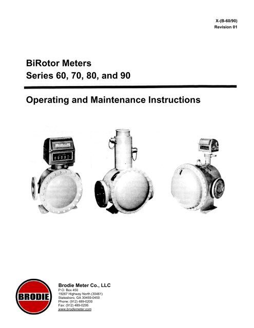
X-(B-60/90)Revision 01BiRotor MetersSeries 60, 70, 80, and 90Operating and Maintenance Instructions<strong>Brodie</strong> Meter Co., LLCP.O. Box 45019267 Highway North (30461)Statesboro, GA 30459-0450Phone: (912) 489-0200Fax: (912) 489-0295www.brodiemeter.com
Essential Instructions<strong>Brodie</strong> Meter Co., LLC designs, manufactures, and tests its products to meet manynational and international standards. The products sold and distributed by <strong>Brodie</strong> MeterCo., LLC are sophisticated technical instruments that must be properly installed, used,and maintained to ensure they continue to operate within their normal specifications.The following instructions must be followed and integrated into your safety programwhen installing, using, and maintaining any of the products purchased from <strong>Brodie</strong>Meter Co., LLC.• Read all instructions prior to installing, operating, and maintaining your equipment. Ifthis manual is not the manual you need, telephone (912) 489-0200, or the local<strong>Brodie</strong> Meter Co., LLC office and the necessary manual will be mailed to you. Savethis manual for future reference.• If you do not understand the instructions, contact your sales representative forclarification.• Follow all warnings, cautions, and instructions marked on, and supplied with yourequipment.• Inform and educate your personnel in the proper installation, operation, andmaintenance of your equipment.• Install and maintain your equipment, and related instrumentation, as specified in themanual instructions and in accordance with local and national codes. Connect allproducts to the proper electrical and pressure sources.• To ensure proper performance, use qualified personnel to install, operate, update,program, and maintain the equipment.• When replacement parts are required, ensure that qualified service personnel usereplacement parts specified by <strong>Brodie</strong> Meter Co., LLC. Unauthorized parts andprocedures can affect the product's performance and endanger your operation.Look-alike substitutions may result in fire, electrical hazards, or improper operation.• Except when maintenance is being performed by qualified persons, ensure allequipment doors are closed and protective covers are in place to prevent electricalshock and personal injury.Instruction Cross ReferenceX-PS01 P-Style BiRotor Meters
Table of ContentsParagraph PageNumber NumberSection 1 INTRODUCTIONGeneral 1-1 1Description 1-2 1Meter Model Number 1-3 1Specifications 1-4 1Section 2 INSTALLATIONGeneral 2-1 2Receipt of Equipment 2-2 2Return Shipment 2-3 2Meter Installation, Storage and Shipment 2-4 2Section 3 OPERATIONGeneral 3-1 3Section 4 INSPECTION AND MAINTENANCEGeneral 4-1 3Disassembly 4-2 4Measuring Unit Disassembly 4-3 4Removing Timing Gears and Rotors 4-4 5Cleaning the Measuring Unit 4-5 5Measuring Unit Assembly 4-6 5Setting End Rotor Clearance 4-7 6Timing Gear Adjustment 4-8 6Meter Adjustment 4-9 6Section 5 TROUBLESHOOTING 7Section 6 PARTS LIST 7List of IllustrationsFigureNumberTitlePageNumber4-1 Proper Method for Blocking Rotors 54-2 Typical Rear End Plate/Bearing Assembly 54-3 Proper Method for Timing Rotors 64-4 Proper Method for Setting Rotor End Clearance 64-5 Model 4200 Accuracy Adjustor 76-1 Complete Meter Assembly - Series 60, 70 and 80 86-2 Complete Meter Assembly - Series 90 106-3 Right Angle Counter Base Plate Assembly 126-4 Measuring Unit Assembly - Series 60 136-5 Measuring Unit Assembly - Series 70 146-6 Measuring Unit Assembly - Series 80 156-7 Measuring Unit Assembly - Series 90 166-8 Counter Base Plate Assembly - Part Numbers 51750-500, 51790-011, 82750-010 and 82750-500 176-9 Counter Base Plate Assembly- Part Number 92150-500 186-10 Shockfree Quantity Control Valve - For Series 60, 70 and 80 Meters 186-11 Shockfree Quantity Control Valve - For Series 90 Meters 196-12 Linkage Assembly - All <strong>Models</strong> 20Table of Contents continued on next page...
TableNumberList of TablesTitlePageNumber1-1 Connections 11-2 Capacities 15-1 Troubleshooting 76-1A Complete Meter Assembly -Series60 96-1 B Complete Meter Assembly - Series 70 96-1C Complete Meter Assembly- Series 80 116-2 Complete Meter Assembly - Series 90 116-3 Right Angle Counter Base Plate Assembly 126-4 Measuring Unit Assembly - Series 60 136-5 Measuring Unit Assembly - Series 70 146-6 Measuring Unit Assembly - Series 80 156-7 Measuring Unit Assembly - Series 90 166-8 Counter Base Plate Assembly - Part Numbers 51750-500, 51790-011, 82750-010 and 82750-500 176-9 Counter Base Plate Assembly- Part Number 92150-500 186-10 Shockfree Quantity Control Valve - For Series 60, 70 and 80 Meters 186-11 Shockfree Quantity Control Valve - For Series 90 Meters 196-12 Linkage Assembly - All <strong>Models</strong> 20
Section 1 INTRODUCTION1-1 GeneralThe <strong>Brodie</strong> BiRotor Meter is a precision made, accurate flowmeasurement device which utilizes the positive displacementprinciple of operation. It is designed to measure crude andrefined petroleum products as well as many industrial liquids.1-2 DescriptionThe standard meter consists of a measuring unit installed inan outer housing or case, an adjustor for calibration andselected registration equipment. "I'" Style BiRotor Metersoffer an electrical output pulse proportional to liquid flow andutilize a pick-off Assembly. No mechanical adjustment orstack-up equipment is required with the P-Style meter.As product enters the intake of the measurement element,two finely timed rotors divide the liquid into precise segmentsof known volume and return those segments to the flowingstream. During this transition, the rotation of the two rotors isdirectly proportional to volumetric throughput. The rotors arealways dynamically balanced, but hydraulically unbalanced,and have no metal-to-metal contact with one another or themeasuring unit housing. Volume indication is determined byeither mechanical output gearing leading to registrationdevices, or by an electrical output signal to remoteregistration equipment.The accuracy adjustor, located on the output shaft of thecounter drive gearing of the mechanical meter, permits theoperator to adjust output registration to read in exact units ofvolume. It allows for adjustments up to +/-3% of meterthroughput in determining accurate measurement. The metermay be supplied with any of several accessory itemsincluding two-stage electric valves, preset counters, highfrequency pulse generators, impulse contactors, etc. Theseunits provide various functions for local and/ or remotecontrol and readout.NOTE: Before placing the meter into service referencethe appropriate instruction manuals for all accessories.This includes hook-up, electrical wiring, andspecification requirements and restrictions.1-3 Meter Model NumberThe meter Model Number, Serial Number, Flow Range andOperating Pressure appear on the nameplate attached to themeter body. This information is vital to proper operation andidentification, and should not be removed for any reason.1-4 SpecificationsThe following specifications apply to the meter unlessotherwise stated.Materials of ConstructionHousing: Welded Steel construction combining castings anddrawn steel plates.Measuring UnitRotors: Heat Treated Aluminum (Standard)6" Series 90 and 92 uses Cast Iron 3-Tooth RotorRotor Shafts: E.T.D.150Rotor Bearings: Stainless SteelBody and End Covers: Cast IronCounter Base Plate (Not used on P-Series)Body: SteelO-Rings: Viton TM (Standard)Counter Base Drive Gears: Stainless SteelDrive Shafts: Stainless SteelDrive Shaft Ball Bearings: Stainless SteelOptional: All Ferrous Materials of ConstructionRatingsWARNING: Do not operate this meter in excess of thevalues specified. Failure to heed warning may result inserious personal injury or damage to equipment.Maximum Safe Working Pressure: 150 psi (1034 kPa)Maximum Safe Working Temperature -20 to 150"F (-29 to65°C).Optional to 325° (162'C) max.Table 1-1 ConnectionsModelConnectionB-62 3" 150 lb. ANSI FlangeB-72 3" 150 lb. ANSI FlangeB-82 4" 150 lb. ANSI FlangeB-92 6" 150 lb. ANSI FlangeB-70 3" or 4" 150 lb. ANSI FlangeB-80 4" or 6" 150 lb. ANSI FlangeB-90 6" 150 lb. ANSI FlangeDBF (All Ferrous Construction) same as DB <strong>Models</strong>.Table 1-2 CapacitiesMAXIMUM CAPACITY -GASOLINE/LIGHT OILSModelU.S.gpmImp.gpmBbls.per HourLitersper Min.B-62 250 208 357 946B-72 425 354 607 1609B-82 600 500 857 2271B-92 1000 833 1430 3785B-70 550 460 785 2082B-80 800 665 1142 3028B-90 1200 1000 1714 4542DBF (All Ferrous Construction) same as DB <strong>Models</strong>.1
Section 2 INSTALLATION2-1 GeneralThis section contains the procedure for receipt andinstallation of the meter. Specific instructions for accessoryequipment should be obtained from individual bulletinscovering those products.2-2 Receipt of EquipmentWhen the equipment is received, the outside of the packingcase should be checked for any damage incurred duringshipment. If the packing case is damaged, the local carriershould be notified at once concerning his liability.A report should be submitted to the Product ServiceDepartment, <strong>Brodie</strong> Meter Co., LLC, P.O. Box 450,Statesboro, Georgia, 30458.Remove the envelope containing the packing list. Carefullyremove the equipment from the packing case. Inspect fordamaged or missing parts.Refer to your packing list for information as to what issupplied with your particular order. In the event that anyitems are missing from your shipment, contact your local<strong>Brodie</strong> representative or Sales Office. The serial number ofyour meter and sales order number should be supplied atthis time.2-3 Return ShipmentTo be able to process return goods quickly and efficiently, itis IMPORTANT that you provide essential information. Donot return any Assembly or part without an"R.M.R."(Returned Materials Report), or a letter whichdescribes the problem, correction action, if any, to be taken,and the work that is to be performed at the factory. R. M.R.forms can be obtained from <strong>Brodie</strong> Sales Offices or theService Department, <strong>Brodie</strong> Meter Co., LLC, P.O. Box 450,Highway 301 N., Statesboro, Georgia, 30458.Place a copy of either of the above inside the shippingcontainer and attach it physically to the material beingreturned. A copy of your packing list should be placed insidean envelope and attached to the outside of the shippingcontainer, or placed inside the container.2-4 Meter Installation, Storage and ShipmentThe following is a general outline for the proper storage,shipment, installation, and start up of any <strong>Brodie</strong> BiRotormeter. Additional information on the proper use of PositiveDisplacement Meters can be obtained from API Standard1101 - Measurement of Petroleum Liquid Hydrocarbons byPositive Displacement Meter.StorageA. <strong>Brodie</strong> meters are precision instruments and should behandled with care. They should not be subjected torough or improper handling or stored in an environmentwhere moisture, extreme temperatures, or foreignmaterial can damage the meter.B. Flange covers must remain on the meter until it isready for installation.C. If extended storage is anticipated under harsh fieldconditions the meters should be stored in waterprooflined wooden boxes. Desiccant packs should be taped tothe inside of the meter flanges to reduce the effects ofhumidity on the measuring element.Caution must be used to insure the desiccant packsare removed prior to installation.D. If the meter is removed from service for an extendedperiod of time it should be flushed with a light oil beforebeing placed into storage. The meter flanges should besecurely covered.ShipmentA. If the meter is removed from service it must be thoroughlydrained and neutralized before it is packed for shipment.Care must be taken to insure that product removed fromthe meter is disposed of in accordance with all applicablelocal, state, and federal laws.B. The flanges should be sealed to keep residual fluid fromleaking out of the meter during transport. The type offlange required will vary with the form of transportationused. Contact the carrier for specific instructions.C. The meter should be securely mounted on a wooden skidfor shipment. The original container supplied by <strong>Brodie</strong> ora solid wooden box should be used to protect the exteriorof the meter.InstallationWARNING: Compounds used in the making of elastomergaskets, O-rings and seals will, by nature, deteriorateover an extended period of time. This is dependent onelastomer material, frequency of operation and theproduct being measured. Extreme caution should beused when measuring volatile liquids or when using ameter that has been stored for an extended period oftime. Loss of seal integrity can result in leakage, damageto equipment and/ or personal injury.A. The BiRotor meter should be mounted on a securefoundation. Considerations for placement of a right angleadaptor and meter weight must be made when verticalinstallation is required.B. Care should be taken insure the drain plug remainsaccessible.1. A valve may be installed on the drain line to facilitatedraining water and sediment from the meter. A lockablevalve is recommended to reduce the chance ofaccidentally draining the meter.2. Any product drained from the meter, either manually orthrough a centralized drain system, must be disposed ofin accordance with local, state and federal laws.C. Skid foundations and process piping must be properlysecured in order to minimize line vibration at the meter.2
D. Process piping should not place undue strain on themeter.E. Provisions should be made to insure that thermalexpansion does not raise line pressure above themaximum pressure rating of the meter.F. All process piping must be clean and free of debris toinsure foreign material does not enter the meter. Forcontinuous protection a strainer should be installedupstream of the meter.G. A flow limiting valve should be installed downstream ofthe meter to maintain adequate back pressure and toprotect the meter from excessive flow rates.H. If required, an air eliminator should be installedupstream of the meter.I. Do not allow water to remain in the meter. If water hasentered the meter remove the inner unit and clean it witha light lubricating oil.J. Standard flow through the meter is from left to right. Ifright to left flow is required, consult your local <strong>Brodie</strong>agent or an authorized repair center.K. The bolt pattern on the meter accessories allows themeter accessory stack to be rotated in 90 degreeincrements. The required position should be selectedprior to installing electrical service to the meter. Careshould be taken not to damage the capillary tube on thetemperature compensator if so equipped.L. Isolation valves should be installed on both ends of themeter run to minimize product loss when removing anyof the components from the line.C. Slowly bleed air from the system through the highpoint vent.D. Once all air has been eliminated, slowly open thedownstream valve. Allow the meter to run atapproximately 20 percent of the maximum rated flow fortwo minutes. Observe the rotation of the counter wheelsto insure the meter is operating smoothly. Continueopening the downstream valve until it is fully open.Care should be taken to insure the maximum flowrate of the meter is not exceeded.Confirm that the setting on the flow control valve isproperly fixed and is in control of the system.E. Do not close valves quickly. This can cause a pressurespike which can damage the meter.F. Do not make adjustments to the meter or its accessorieswhile the meter is turning. When adjustor settings arechanged, a small batch should be run through the meterprior to making the next proving run. This allows theadjustor components to shift to the new setting.G. Prove the meter in order to establish a meter factorunder actual operating conditions. Proving records andother pertinent meter data should be retained in order toestablish a performance history for the meter.<strong>Brodie</strong> Meter Co., LLC has highly qualified servicetechnicians who are available to provide start upassistance. Contact <strong>Brodie</strong> Statesboro or your local<strong>Brodie</strong> Authorized Repair Center if service assistance isrequired.Section 3 OPERATIONCAUTION: Do not operate this meter in excess of thevalues stated in Section 1-4 Specifications.3-1 GeneralThe following recommendations should be considered whenthe meter is first put into operation or any time that the meterhas been drained.Starting Flow Through the MeterA. If large volumes of debris are expected in the processpiping during start up it is recommended that themeasuring element be removed from the meter until thelines are free of pipe scale, weld beads and other typesof foreign material. A spool piece may be used as atemporary replacement for the meter. The strainerbasket should be removed to eliminate the possibility ofrupturing.B. Slowly introduce product into the meter. Open theupstream valve while the downstream valve remainsclosed.Section 4 MAINTENANCEWARNING: Extreme care must be exercised when themeasuring chamber is exposed and handled. Handsmust be kept clear of the timing gears, rotors andmeasuring chamber or serious personal injury canoccur. Due to the precision balance of the rotors andtiming gears, they can be set in motion very easily. Keephands clear of these parts at all times. At no time shouldhands be used to brace these parts while servicing.4-1 GeneralThe amount of maintenance necessary for efficient meterperformance depends upon such factors as:A. Continuity of Operation - A meter which operatescontinuously, will require more attention than one onintermittent duty.B. Rate of Flow - The practical life of any piece ofequipment is proportional to its speed of operation. Ameter operating at, or close to, its maximum rating willhave a shorter life than one operating at a reduced rate.3
C. Lubricating Value of Product - A meter handling a lightlubricating oil will have a longer service life than onemeasuring a dry motor fuel.D. Cleanliness of Product - Abrasive solid materialentrained in the measured product will accelerate wear.All meters should receive routine maintenance checks toavoid potential problems that could lead to failure. To aconsiderable extent, a meter's performance is dependent onthe proper functioning of accessory equipment in use. Thefollowing list highlight some of the conditions and factors thatmay influence meter performance.1. A meter should be kept filled with the liquid it ismeasuring. Draining results in the formation of depositswhich increase mechanical friction, thus decreasingservice life. Any leaking shut-off or check valves shouldbe repaired or replaced.2. A petroleum meter should be kept free of water. Undernormal circumstances regular inspection and drainageof storage tanks is sufficient protection.3. Clean the strainer basket frequently.4. Soft closing loading valves or shock chambers foreliminating water hammer should be kept in goodworking order.5. The valves and operating mechanism of an aireliminator should be inspected on a routine basis. Thisis especially true where a critical air condition exists. Forthis reason meter performance is dependent on properair elimination. Factors leading to difficult valve and aireliminator operating conditions include: gum formationscaused by alternate wetting and drying, formation ofcorrosive vapors, and presence of salt air.6. The meter counter should be protected from extremeweather and any potential hazardous condition.7. A meter taken out of service for any length of timeshould be filled with light lubricating oil.8. Proper Service Bulletins should be available forreference at all times.4-2 DisassemblyCleanliness is of prime importance when working on aprecision instrument. The work area should be clean and themeter parts thoroughly washed. All Gaskets and O-Ringsshould be removed, examined and replaced as required.This policy will assure maximum performance from your<strong>Brodie</strong> BiRotor Meter at less expense and with greateraccuracy.Removing the Measuring UnitReference Figures 6-1 through 6-12 and Tables 6-1 through6-12 for basic part identification.WARNING: All pressure must be relieved, flow stopped andelectrical connections to the meter disconnected before anydisassembly can take place. Failure to comply can result inserious personal injury and/or damage to the equipment.Service should be performed by trained and qualifiedpersonnel only.1. Remove the Drain Plug and completely drain themeter.2. Remove the Accuracy Adjustor and Counter BasePlate Assembly.3. Remove Hex Nuts and Housing Cover from theMeter Housing.4. Disconnect the Measuring Unit from the Meter Housingby first removing the Screws, Washers and SealWashers from the unit.5. Carefully lift the Measuring Unit away from the meterbody and place on a clean dry surface.6. The Measuring Unit may now be inspected. In somecases, a thorough washing in cleaning solvent orkerosene will be sufficient to free the Rotors of corrosionor foreign material. In the event that solid material orcorrosion prevents proper operation it will be necessaryto remove the Rotors and Rear End Cover Assembly forfurther cleaning.WARNING: Extreme care must be exercised when theMeasuring Unit Assembly is exposed or handled. Hands mustbe kept clear of all Gears and Rotors or serious personalinjury can occur. Due to the precision of the Rotors and DriveGears, they can easily beset into motion. Keep Hands clearof these parts at all times. At no time should the hands beused to brace these parts while servicing.4-3 Measuring Unit Disassembly1. Position the Measuring Unit with the Front End Platefacing out in such away as to afford easy access. Thiswill vary according to the size of the meter beingserviced. It is recommended that a cradle type structurebe used for the disassembly of most models. ReferenceFigure 4-1.2. Remove the two front Bearing Retainer Caps(Series90 Meters).3. Remove the Drive Gear Assembly, Retainer Ring andKey (if applicable) and Bearings from the 3-Tooth Rotor.4. Remove the Screw, Washer, Bearing Key andBearings from the 4-Tooth Rotor.DO NOT remove the Front End Plate at this time.5. Rotate the Measuring Unit, remove Screws from theRear End Cover and separate from the Measuring UnitBody.4
6. The Rotors and Rear End Cover can now be washedthoroughly with solvent or kerosene and inspected. If theRotors show no evidence of contact with each other,and if the Timing Gears appear satisfactory, furtherdisassembly will not be required.4-4 Removing Timing Gears and RotorsSevere scoring of the Rotors, or grit in the Bearings, maynecessitate removal of the Rotors from the Rear End Cover.1. Remove Lock Nut Retainer and Washer.2. Using a small piece of rubber, or nylon stock, blockthe Timing Gears.4. Ball Bearing should be cleaned and inspected forwear.5. All Gears and Shafts in the Rear End Cover Assemblyshould be inspected. Check all O-Rings and Gaskets forwear and/or distortion and replace as required.NOTE: All parts should be thoroughly cleaned insolvent, light fuel oil, kerosene or a suitable cleaningagent compatible with the metallurgy of the meterand the liquid being measured.4-6 Measuring Unit Assembly1. Lubricate all Bearings and O-Rings with a lightweight oil.2. Position the Measuring Unit Body and attach theFront End Plate by installing Screws.3. Rotate the Measuring Unit Body and replace the Rotorsin the proper slots with the tapered end of the Rotorsupward.4. Position and attach the Rear End Plate using theScrews previously removed.5. Install the Bearings within the bearing bore of theRear End Plate.Figure 4-1 Proper Method for BlockingR3. Timing Gears are taper fitted to the shafts and can beremoved one at a time by striking the inside face of the gear(do not strike teeth) with a rubber mallet.Care should be taken not to damage the Rotor Shaftthreads when removing the Timing Gears.4. Remove the Bearing Spacers and Bearings from theRear Cover.NOTE: Ball Bearings can be removed from the EndCovers by gently tapping or pressing on the inner raceof the Bearings from the inside of the End Cover.5. Separate the Rotors from the Rear End Cover.NOTE: The slot on the outer race of the Ball Bearingmust align with the Roll Pin in the bottom of thebearing bore.6. Position a Bearing Retainer (Series 90) or Spacer overeach Bearing and attach by installing Lock Washers andScrews.7. Replace the Spacer Key (if applicable), Timing Gears,Lock Nut Retainer, Lock Washer and Screws.NOTE: The large Timing Gear fits on the 4-toothRotor. The short tab on the Spacer Key fits in theinner race of the Ball Bearings and the longer tabseats into the slot on the Timing Gear.6. Remove the Front End Cover and Bearings.4-5 Cleaning the Measuring Unit1. Scored metal should be removed with a file takingcare only to remove the high points.Do not remove any more metal than is necessary.2. Wash thoroughly insolvent or kerosene to remove allparticles of grit or metal.3. Lightly file the End Covers to remove any burrs or highspots. Use fine sand paper to remove corrosion and burrsfrom the surface of the bores that house the Bearings.Figure 4-2 Typical Rear End Plate/BearingA bl5
8. Replace Lock Washers and Lock Nuts. The tab on theLock Washer must seat into the slot on the Timing Gear.9. Rotate the body and install Bearings, Bearing Key, SnapRing, Lock Washer and Screws onto the Front EndCover.NOTE: The tab on the Bearing Key must seat intothe slot on the inner race of the Bearing.10. The Measuring Unit must have Rotor clearance asdescribed in Sections 4-7 and 4-8.4-7 Setting End Rotor ClearanceNote: End rotor clearance is not required on all models.Units requiring end rotor clearance can be identified bythe presence of set screws on the face of Timing Gears.1. Adjust the two Set Screws located on the face of theTiming Gears until both Rotors are flush with the backside of the Rear End Plate.2. Insert a shim into the outlet port, located on the FrontEnd Plate, and determine the total distance between thebackside of the Front End Plate and the 3-tooth Rotor.Repeat this procedure for the 4-tooth Rotor.3. Adjust the two Set Screws located on the small TimingGear until the distance between the back side of theFront End Plate and the 3-tooth Rotor is one-half thedistance previously determined. Repeat this procedurefor the 4-tooth Rotor and the large Timing Gear.4. If the end clearance is adjusted properly, the Rotors willspin freely in any position. If the Rotors fail to spin freely,repeat procedure for setting end clearance.NOTE: This may be done through the inlet and outletopenings of the unit.2. Position the Measuring Unit into the Meter Housing sothat the inlet on the Measuring Unit couples with the inleton the Meter Housing.3. Replace Screws, Washers and Seal Washersattaching the Measuring Unit to the Meter Housing.4. Replace the Meter Cover Housing and the Front DomeGasket. A light film of grease will aid in holding theGasket in place.5. Rotate the Coupling Tube on the Pinion Shaft Assemblyof the Counter Base Plate Assembly until the Drive Pin ispositioned the same as the slot of the Coupling Jaw onthe Counter Drive Gear Train.6. Install the Adjustor and all other accessories. SeeSection 3 - Operation for Start-up recommendationsFigure 4-4 Proper Method for Setting Rotor EndCl4-9 Meter AdjustmentThe standard mechanical BiRotor meter is supplied with aSeries 4200 Adjustor whereby incremental changes can bemade to calibrate meter output with registration equipment.This is accomplished by changing the gear ratio between themeter packing Shaft and the Counter. To make adjustments:1. Remove the protective security cover of the Adjustor.Figure 4-3 Proper Method for TimingR4-8 Timing Gear Adjustment1. Loosen the Jam Nut on the large Timing Gear and witha feeler gauge or shims, carefully centralize a lobe of the3-toothed Rotor in a flute of the 4-toothed Rotor.Determine the distance between the lobe and the flute ofthe two Rotors and shim the Rotors one-half of thedetermined distance between them.62. Lift the Adjustor Locking Plate.3. Adjust the meter as required.Adjustment Knobs are labeled for COARSE and FINEadjustment. Each groove of the COARSE adjustmentequals 0.6% of the volume delivered. Each groove of theFINE adjustment is equal to 0.05% of the volumedelivered.NOTE: Pushing the adjustment knobs IN decreasesthe counter reading. Pulling the adjustment knobsOUT increases the counter reading.
Section 6 PARTS LISTFigure 4-5 Model 4200 AccuracyAdjReference Figures 6-1 through 6-12 and Tables 6-1 through6-12 for complete parts list information for the basic <strong>Brodie</strong>BiRotor Meter Series 60 through 90. Reference Instruction<strong>Manual</strong> X-PS01 for parts pertaining to the P-Style Meter. Forparts not listed, or for additional information, consult factory.When ordering, the following information must be furnished.1. Part Number and Description2. Model Number of Flow meter3. Serial Number of Flow meter4. Quantity RequiredWhen ordering items of a material or special construction notindicated in the parts list, the Specific Material ofConstruction must be included.P-Style BiRotor meters are adjusted electronically at thepoint of registration using meter factor information andrequire no mechanical adjustor. Reference Instruction<strong>Manual</strong> X-PS01 for complete adjustment details.Section 5 TROUBLESHOOTINGTable 5-1 has been provided to aid in basic troubleshooting.Disassembly procedures are covered in Section 4-Maintenance.If the flow meter is found to be in need of repair, it isrecommended that the user contact the nearest <strong>Brodie</strong> Serviceor Sales Office. It is important that service be performed bytrained and qualified service personnel.Table 5-1 TroubleshootingSymptoms Possible Cause Service RequiredMeter runs butcounter does notregister.Meter runs but isnoisy.Faulty RegisterFaulty adjustor or broken couplingbetween adjustor and counter baseplate.Meter is not timed properly.Damaged RotorsWorn ball bearings.Damaged gears in counter baseplate Assembly.Remove register and see if output shaft on adjustor rotates withmetered fluid flow. If output shaft on adjustor rotates, replace register.Remove adjustor and see if output shaft on counter base plate rotateswith metered fluid flow. If output shaft of counter base plate Assemblyrotates, then inspect the following:1. Check coupling on input shaft of adjustor to see if it is broken.If broken, replace coupling.2. If coupling is not broken, replace adjustor.Check rotor clearances as described in Section 4-8. If discrepancy isfound, re-time rotors.Remove rotors as described in Section 4-4. If rotors are scored orgalled, clean them as described in Section 4-5. If rotors are damagedbeyond repair, replace with a new set. Install rotors as described inSection 4-6.Remove ball bearings as described in Section 4-4. Check to see ifball bearings turn freely with no free play. If discrepancy is found,replace ball bearings and install as described.Disassembly counter base plate Assembly. Check for worn or damagedgears. Replace gears as necessary and reassembly.7
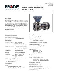
8Figure 6-1 Complete Meter Assembly - Series 60, 70 and 80
Table 6-1A Complete Meter Assembly - Series 60MeterModelB-62DB Standard MetallurgyB-62DBF All FerrousItem DescriptionQtyRqd1 Gal. PerRevolution10 Gal. PerRevolution10 Liters perRevolution1 Gal. PerRevolution10 Gal. PerRevolution10 Liters perRevolutionComplete Meter Assy. 62300-000 62300-010 62300-020 62300-001 62300-011 62300-0211 Measuring Unit 1 62305-000 62305-010 62305-020 62305-001 62305-011 62305-0213 Screw 4 151052 151052 151052 151052 151052 1510524 Housing Cover 1 62430 62430 62430 62430 62430 6243016 Nut 24 151545 151545 151545 151545 151545 15154517 Screw 24 150766-008 150766-008 150766-008 150766-008 150766-008 150766-00819* Gasket 1 60434 60434 60434 60434 60434 6043420 Meter Housing 1 62415 62415 62415 62415 62415 6241522 Drain Plug 1 154707 154707 154707 154707 154707 15470723 Lead Washer 1 151841 151841 151841 151841 151841 15184126* Counter Base Plate Gasket 1 51156 51156 51156 51156 51156 5115627 Counter Base Plate Assy. 1 51750-500 517500-500 82750-500 51790-011 51790-011 82750-01028 Screw 9 151253 151253 151253 151253 151253 15125329 Lead Seal 2 151831 151831 151831 151831 151831 15183130 Seal Wire 2 155051 155051 155051 155051 155051 15505131* Adjustor 1 4200 4200 4200 4200 4200 420032 Name Plate 1 30202 30202 30202 30202 30202 3020233 Drive Screw 4 153991 153991 153991 153991 153991 15399135 Screw 4 150565 150565 150565 150565 150565 15056543 Steel Washer 4 151882 151882 151882 151882 151882 15188244 Stat-O-Seal 4 152034 152034 152034 152034 152034 152034* Recommended Spare Part.Table 6-1 B Complete Meter Assembly - Series 70Meter ModelB-70C8, B-72DB Standard Metallurgy B-72DBF All FerrousItem DescriptionQtyRqd1 Gal. perRevolution10 Gal. perRevolution10 Liters perRevolution1 Gal. perRevolution10 Gal. perRevolution10 Liters perRevolutionComplete Meter Assy. - CB 70500-000 70500-010Complete Meter Assy. - DB 72500-000 72500-010 72500-020Complete Meter Assy. - DBF 72500-001 72500-01 t 72500-0211 Measuring Unit 1 72505-000 72505-010 72505-020 72505-001 72505-011 72505-0213 Screw 4 151026 151026 151026 151026 151026 1510264 Housing Cover 1 62890 62890 62890 62890 62890 6289016 Nut 22 151555 151555 151555 151555 151555 15155517 Screw 22 150803 150803 150803 150803 150803 15080319* Gasket 1 178709 178709 178709 178709 178709 17870920**' Meter Housing 1 72925-005 72925-005 72925-005 72925-005 72925-005 72925-00522 Drain Plug 1 154718-024 154718-024 154718-024 154718-024 154718-024 154718-02426* Counter Base Plate Gasket 1 51156 51156 51156 51156 51156 5115627 Counter Base Plate Assy 1 82750-500 51750-500 82750-500 82750-010 51790-011 82750-01028 Screw 9 151251 151251 151251 151251 151251 15125129 Lead Seal 2 151831 151831 151831 151831 151831 15183130 Seal Wire 2 155051 155051 155051 155051 155051 15505131* Adjustor 1 4200 4200 4200 4200 4200 420032 Name Plate 1 30202 30202 30202 30202 30202 3020233 Drive Screw 4 153991 153991 153991 153991 153991 15399135 Screw 4 150565 150565 150565 150565 150565 15056543 Steel Washer 4 151882 151882 151882 151882 151882 15188244 Stat-O-Seal 4 152034 152034 152034 152034 152034 152034* Recommended Spare Part.** B-7008 with 4" Flanges, order Part Number 70715-000 Meter Housing9
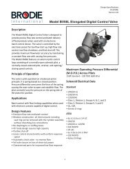
10Figure 6-2 Complete Meter Assembly - Series 90
Table 6-1C Complete Meter Assembly- Series 80MeterModelB-BOCB B82DB Standard MetallurgyB-82DBF All FerrousItem Description Qty.Req.10 Gal. perRevolution10 Liters perRevolution10 Gal. perRevolution10 Liters perRevolutionComplete Meter Assy. - CB 80000-010Complete Meter Assy. - DB 82800-012 82800-022Complete Meter Assy. - DBF 82800-014 82800-0241 Measuring Unit 1 82805-012 82805-022 82805-014 82805-0243 Screw 4 151070 151070 151070 1510704 Housing Cover 1 82890 82890 82890 8289017 Screw 22 150832 150832 150832 15083219* Gasket 1 82884 82884 82884 8288420 + Meter Housing 1 82925 82925 82925 8292522 Drain Plug 1 154718-024 154718-024 154718-024 154718-02426* Counter Base Plate Gasket 1 51156 51156 51156 5115627 Counter Base Plate Assy 1 51750-500 82750-500 51790-011 82750-01028 Screw 9 151251 151251 151251 15125129 Lead Seal 2 151831 151831 151831 15183130 Seal Wire 2 155051 155051 155051 15505131* Adjustor 1 4200 4200 4200 420032 Name Plate 1 92802 92802 92802 9280233 Drive Screw 8 153974 153974 153974 15397435 Screw 4 150565 150565 150565 15056544 Stat-O-Seal 4 151845 151845 151845 151845* Recommended Spare Part.+ For 80000-000 and 80000-010 Housing Assembly 80415 is used in place of 82925.Table 6-2 Complete Meter Assembly - Series 90Item Description Quantity Required B-90CB and B-92 DEB10 Gallons per Revolution 92400-012100 Liters per Revolution 92400-0441 Barrel per Revolution 92400-0321 Screw 4 1505652* Adjustor 1 42003 Screw 9 1512514 Counter Base Plate Assembly 1 92150-5005* Counter Base Plate Gasket 1 511566 Nut 32 1515587 Meter Housing Assembly 1 924158 Cap Screw or Nut 32 1508479 Measuring Unit- 10 Gallons per Revolution 1 92205-010- 1 Barrel per Revolution 1 92205-044- 100 Liters per Revolution 1 92205-03010* Meter Housing Cover Gasket 1 9243411 Meter Housing Cover 1 9243012 Pipe Plug 1 154784-02413* Seal Washer 7 15203114 Washer 7 15190315 Screw 7 15105418 Lead Seal 2 15183119 Seal Wire 2 155051Name ate 1 9280221 Drive Screw 4 153974* Recommended Spare Part.11
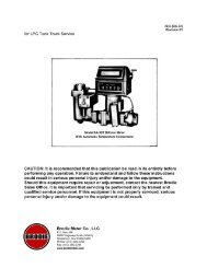
Table 6-3 Right Angle Counter Base Plate AssemblyCom late Rioht An le Counter Base Plate ModelB-62DB -1 and 10 GPR B-82DB - 10 LPR B-92DEB - All RegistrationsB-72DB - 10 GPR B-72DB - 1 GPR and 10 LPRQty. B-82DB - 10 GPR B-82DB - 1 GPR and 10 LPRItemDescriptionReq. Part Number 72700-007 Part Number 72700-008 Part Number 92700-0401 Base Plate Housing 1 72701 72701 727012 Screw 9 151012 151012 1510123 O-Ring 1 152064-022 152064-022 152064-0224 Thrust Washer 1 72728 72728 727285 Packing Gland 1 43175 43175 431756 Screw 4 150535 150535 1505357 Packing Shaft 1 72725-003 72725-003 727258 Screw 4 151253 151253 1512539 Gear Bracket 1 72721 72721 7272110 Bushing 3 92027-005 92027-005 92027-00511 Set Screw 2 150975 150975 15097512 Miter Gear 1 72729-003 72729-003 7272913 Washer 1 151894 151894 15189414 Worm and Gear Bracket Assy 1 W51785-007* W51675-002* W92705-040**15 Bracket Retainer 1 72710-007 72710-007 72710-40016 O-Ring 1 152070-022 152070-022 152070-02217 Lock washer 8 152113 152113 15211318 Screw 4 150725 150725 15072519 O-Ring 1 152073-022 152073-022 152073-02220 Coupling and Shaft with Item 21 1 72735 72735 7273521 Groove Pin 1 153515 153515 15351522 Gear and Shaft Assembly 1 72730-003 72730-003 7273023 Thrust Bearing 1 155171 155171 72728* Includes Items 15, 17 and 18** Includes Item 15 Only12Figure 6-3 Right Angle Counter Base Plate Assembly
Table 6-4 Measuring Unit Assembly - Series 60Meter ModelB-62DB Standard MetallurgyB-62DBF All FerrousItem Description OutputPer RevolutionQtyRqd1 Gal. perRevolution10 Gal. perRevolution10 Liters perRevolution1 Gal. perRevolution10 Gal. perRevolution10 Liters perRevolution*** Complete Meter Assy. 62305-000 62305-010 62305-020 62305-001 62305-011 62305-0211 Meter Body 1 62212-000 62212-000 62212-000 62212-000 62212-000 62212-0002 Rear End Plate 1 60266-015 60266-015 60266-015 60266-015 60266-015 60266-0153 Front End Plate 1 60230-000 60230-000 60230-000 60230-000 60230-000 60230-0004** Rotor - Four Tooth 1 60586 60586 60586 60586-001 60586-001 60586-0015** Rotor - Three Tooth 1 60276 60276 60276 60276-001 60276-001 60276-0016* Ball Bearing 4 154953 154953 154953 154953 154953 1549537** Timing Gear - Three Lobe 1 60591 60591 60591 60591 60591 605918** Timing Gear - Four Lobe 1 60596 60596 60596 60596 60596 6059611 Bearing Spacing Key 2 60294 60294 60294 60294 60294 6029413* Drive Gear 1 60537 (55T) 60542 (14T) 60542 (14T) 60537 (55T) 60542 (14T) 60542 (14T)14* Compound Gear Assembly 1 62330 (27T-24T) 62335 (69T-24T) 62335 (69T-24T) 62330 (27T-24T) 62335 (69T-24T) 62335 (69T-24T)15 Lock Nut 2 60592 60592 60592 60592 60592 6059216* Lock Washer 2 51593 51593 51593 51593 51593 5159318 Coupling Jaw Shaft i 72542 72542 72542 72542 72542 7254219* Gear 1 62328(50T) 62328(50T) 62329(53T) 62328(50T) 62328(50T) 62329(53T)20* Stub Shaft 1 51579 51579 51579 51579 51579 5157922 Groove Pin 1 153636-019 153636-019 153636-019 153636-019 153636-019 153636-01923 Retainer Ring 1 156484 156484 156484 156484 156484 15648430 Bushing 4 155151 155151 155151 155151 155151 15515134 Screw 1 150156 150156 150156 150156 150156 15015635 Lock Washer 1 152270-019 152270-019 152270-019 152270-019 152270-019 152270-01936 Bearing Key 2 60238 60238 60238 60238 60238 6023837 Retaining Ring 1 153953 153953 153953 153953 153953 15395339 Dowel Screw 4 51567 51567 51567 51567 51567 5156740 Allen head Screw 5 151010 151010 151010 151010 151010 15101041 Allen head Screw 8 151033 151033 151033 151033 151033 15103342 Rear Gear Cover 1 61601 61601 61601 61601 61601 6160143 Washer 4 151907 151907 151907 151907 151907 15190747 Roll Pin 4 153547 153547 153547 153547 153547 15354748 Set Screw 4 150969 150969 150969 150969 150969 150969* Recommended Spare Part.** Items 4 and 5 are supplied as a set. Items 7 and 8 are supplied as a set.*** Measuring Unit 62305-XXX above are used on meters shipped after January, 1980.Figure 6-4 Measuring Unit Assembly - Series 6013
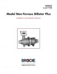
Table 6-5 Measuring Unit Assembly - Series 70Meter ModelB-70CB. B-72DB Standard Metallurgy B-72DBF All FerrousItem Description OutputPer RevolutionQtyRqd10 Gallons perRevolution10 Liters perRevolution10 Gallons perRevolution10 Liters perRevolution*** Complete Meter Ass y. 72505-010 72505-020 72505-011 72505-0211 Meter Body 1 72211-001 72211-001 72211-001 72211-0012 Rear End Plate 1 72267 72267 72267 722673 Front End Plate 1 72818-002 72818-002 72818-002 72818-0024** Rotor - Four Tooth 1 72286 72286 72286-001 72286-0015** Rotor - Three Tooth 1 72276 72276 72276-001 72276-0016* Ball Bearing 4 154952 154952 154952 1549527** Timing Gear-Three Lobe 1 72291 72291 72291 722918** Timing Gear - Four Lobe 1 72296 72296 72296 7229611 Bearing Spacing Key 2 72541 72541 72541 7254113* Drive Gear 1 72555 (29T) 72555 (29T) 72555 (29T) 72555 (29T14* Compound Gear Assembly 1 72550 (21T-79T) 72550 (21T-79T) 72550 (21T-78T) 72550 (21T-78T)15 Lock Nut 2 60592 60592 60592 6059216* Lock Washer 2 51593 51593 51593 5159318 Coupling Jaw Shaft 1 72542 72542 72542 7254219* Gear 1 72455 (46T) 72546 (48T) 72544 (46T) 72546 (48T)20* Idler Shaft 1 50244 50244 50244 5024423 Screw 5/ 16 - 18 x 1-3/4' 2 151038 151038 151038 15103829 Bushing 1 155152 155152 155152 15515234 Screw 1 150156 150156 150156 15015635 Lock Washer 1 152108 152108 152108 15210836 Bearing Key 1 72238 72238 72238 7223837 Retaining Ring 1 156484 156484 156484 15648439 Dowel Screw 4 51567 51567 51567 5156740 Screw 5/16 - 18 x 5/8' 6 151037 151037 151037 15103741 Screw 5/16 - 18 x 1-1 /2" 6 151460 151460 151460 15146042 Rear Gear Cover 1 71601 71601 71601-001 71601-00143 Washer 4 151907 151907 151907 15190745 Bushing 2 155151 155151 155151 15515147 Roll Pin 4 153548 153548 153548 15354848 Set Screw 4 150969 150969 150969 15096989 Washer 1 151902 151902 151902 151902* Recommended Spare Part.** Items 4 and 5 are supplied as a set. Items 7 and 8 are supplied as a set.*** Measuring Unit 72505-XXX above are used on meters shipped after January, 1980.14Figure 6-5 Measuring Unit Assembly - Series0
Table 6-6 Measuring Unit Assembly - Series 80Meter ModelB-80CB, B-82DB Standard Metallurgy B-82DBF All FerrousItemDescription OutputPer RevolutionOtyRqd10 Gallons perRevolution10 Liters perRevolution10 Gallons perRevolution10 Liters perRevolution"" Complete Meter Ass y. 82805-012 82805-022 82805-014 82805-0241 Meter Body 1 82211-002 82211-002 82211-002 82211-0022 Rear End Cover 1 82267-002 82267-002 82267-002 82267-0023 Front End Cover Assembly 1 82835-001 82835-001 82835-001 82835-0014** Rotor- Four Tooth 1 82286 82286 82286-001 82286-0015** Rotor - Three Tooth 1 82276 82276 82276-001 82276-0016* Ball Bearing 4 154951 154951 154951 1549517** Drive Gear (Three-Tooth Rotor 1 82291 82291 82291 822918** Drive Gear (Four-Tooth Rotor) 1 82296-002 82296-002 82296-002 82296-00211 Spacer 2 82833 82833 82295 8229513 Bearing Dowel 2 102268 102268 102268 10226815 Gear Locknut 2 82592 82592 82592 8259216' Gear Retainer 2 82593 82593 82593 8259319* Gear (58T) 1 82860 82860 82860 8286020* Compound Gear Assembly (95T-35T) 1 82845-002 82845-002 82845-002 82845-00228 Set Screw 4 150975 150975 150975 15097529 Flanged Bushing 1 155148 155148 155148 15514830 Bushing 1 155147 155147 155147 15514731 Retaining Ring 3 156514 156514 156514 15651432 Thrust Washer 3 151938 151938 151938 15193833 Coupling Shaft 1 82802-001 82802-001 82802-001 82802-00134* Gear 1 82827 (53T) 82843 (56T) 82827 (53T) 82843 (56T)39 Screw 11 151467 151467 151467 15146740 Screw 7 151017 151017 151017 15101741 Screw 2 151028 15102842 Rear Gear Cover 1 82601 82601 - -43 Nylok Screw 1 150765-014 150765-014 150765-014 150765-01444 Bearin Key 1 82238 82238 82238 8223845 Dowel Screw 4 92567 92567 92567 9256746 Screw () (9) 151026 (9) 151026 (11) 151026 (11) 15102689 Washer 1 151883 151883 151883 151883* Recommended Spare Part.** Items 4 and 5 are supplied as a set. Items 7 and 8 are supplied as a set.*** Measuring Unit 82805-XXX above are used on meters having serial numbers 7805-18601 and above.Figure 6-6 Measuring Unit Assembly - Series8015
Table 6-7 Measuring Unit Assembly - Series 90ItemDescriptionQty.Req.B-90CBB-92DEB10 Gallons Per Revolution 92205-010100 Liters Per Revolution 92205-0441 Barrel Per Revolution 92205-0301 Socket Head Ca Screw 11 1510442 Rear Gear Cover 1 926563 Meter Body 1 922114 Front End Cover 1 92231-0065 Screw 6 1510406* Ball Bearing 4 1549577 Lock washer 2 1521108 3/8 - 16 x 1 Hex Cap Screw 2 1507669 Lock washer 12 15210810 1/4 - 20 x 5/8 Hex Ca Screw 12 15072611 Front Bearing Cap 2 9223912 Dowel Screw 6 9256713** Rotor - Three Tooth Cast Iron 1 92275-00114 Bearing Dowel 4 10226815 Rear End Cover 1 92266-00616 Rotor Spacer Assembly 2 9229517** Timing Gear - Three Lobe 1 9229118* Gear Retaining Lock washer 2 9259319 Gear Locknut 2 9259220 Screw 8 15053821 Lock washer 10 15225922 Worm Shaft Assembly1 92665-00610 Gallons Per Revolution100 Liters Per Revolution 1 92665-0071 Barrel Per Revolution 1 9268023 Bushing 2 9265724 Worm Wheel Shaft 1 9268925 Bearing Retainer 2 9223827 Coupling Jaw 1 9266328 Set Screw 6 15097529 Gland Assembly 1 9266030 Worm Wheel1 92686-00610 Gallons Per Revolution1 Barrel Per Revolution 1 92676100 Liters Per Revolution 1 92686-00732** Timing Gear - Four Tooth 1 9229633** Rotor- Four Tooth Aluminum 1 9228634 Screw 2 15058135 Rear Gear Cover Assembly1 92655-01010 Gallons Per Revolution100 Liters Per Revolution 1 92655-0071 Barrel Per Revolution 1 92675* Recommended Spare Part.** Items 17 and 32 are supplied as a set. Items 13 and 33 are supplied asa set.NOTE: For a Cast Iron Rotor set on Items 13 and 33, order Part No.92275-001 and 92286-001.Figure 6-7 Measuring Unit Assembly - Series 90** Series 90ItemPart NumberRotor Set (Standard) W92275-001Rotor Set (Cast Iron) W92275-011Timing Gear SetW92291Measuring Unit Housing (includes Body W92211and End Plates)16
Table 6-8 Counter Base Plate AssemblyQty.Counter Base Plate Part NumberItem Description Rqd. 51750-500 51790-011 82750-010 82750-5001 Base Assembly 1 51775-501 51775-501 51775-501 51775-5012 Mounting Block 1 51761-300 51761-501 51761-501 51761-3003 Bracket Assembly 1 51760-500 51760-001 51760-001 51760-5004' Packing Shaft & Gear Assembly 1 51785-500 51785-500 51675-001 51675-0015 Bevel Pinion 1 51769-500 51769-500 - -6 Roll Pin 1 153549 153549 -7 Pinion Shaft Assembly 1 51765 51765 51665 516658 Packing Gland 1 52153-011 52153-011 52153-011 52153-0119 Screw 2 150533 150533 150533 15053310* O-Ring 1 157303-022 52176-500 (gasket) 52176-500 (gasket) 157303-02211* O-Ring 1 152064-022 152064022 152064-022 152064-02212* Bearing 1 155195 155195 155195 15519513 Adjustment Collar 1 24371 2437115 Washer 1 151891 151891 151891 15189116 Spring Clip 1 153942 15648417 Spring Clip 1 153942 15394218 Set Screw 2 - - 150969 15096919 Shim .005 AS rqd. 741-12-006-03 741-12-006-020 Shim .010 AS rqd. 741-12-006-04 741-12-006-0421* Bevel Gear and Pinion Gear Assembly 1 W51760-500 W-51760-011 W82750-011 W82750-501consisting of items 3, 4, 5, 6, 7,11, 12, 13, 15,16, 17, 18, 19 and 20Inc. Items 23 & 24 Inc. items 22 & 2322 Screw 4 150527 150527 150527 15052723 Lock Washer 4 152257-019 152257-019 152257-019 152257-01924 Screw 2 150529 150529 1 150529 150529* Recommended Spare Part.Figure 6-8 Counter Base Plate Assembly- Part Numbers 51750-500, 51790-011, 82750-010 and 82750-50017
Table 6-9 Counter Base Plate AssemblyItem DescriptionQty.Rqd. B-92DEBCounter Base Plate Assembly 92150-5002 Packing Shaft Bearin 1 92777-5003 Packing Shaft Positioner 1 921524' 6-Rin 1 157303-0225 Counter Base Plate 1 51775-5016 Packing Gland Assembly 1 52153-0117" O-Ring 1 152064-0228 Screw 2 1505339 Set Screw 2 15096910 Washer 1 15189112 Lock Washer 3 15225913 Screw 3 15057614 Coupling Tube Assembly 1 92155-50015 Washer 1 15189416 Mounting Block 1 51761-30117 Screw 2 I 150529* Recommended Spare Part.Figure 6-9 Counter Base Plate AssemblyTable 6-10 Shock-Free Quantity Control Valve - Series 60, 70 and 80 MetersQty Part NumberItem Description Rqd 72450 72480 82950 829803 End Flange 1 72452 72482 82952 829824 Snap Ring 1 153958 153958 153958 1539585 Spacer 1 62958 62958 62958 629586 Name Plate 1 62957 62957 62957 629577' O-Ring 2 152071-022 152071-022 152071-022 152071-0228 Shaft 1 62956 62956 82956 829569 Lever 1 137478 137478 137478 13747810 Spring 1 62976 62976 540031 54003118` O-Ring 1 152078 152078 152083 152094-02219' O-Ring 1 152074-022 152074-022 157033-022 157033-02220 Piston Assy. 1 62970 62970 82970 8297021 Nut () 151545 (6) 151545 (6) 151591 (8) 151591 (8)22 Body 1 72451 72481 82951 8298125 Washer 1 151839 151839 151839 15183926 Nut 1 151689 151689 151689 151689Qty PartNumberItem Description Rqd 72450 72480 82950 8298027 Cap 1 62967 62967 62967 6296728' O-Ring 1 157080-022 157080-022 157027-022 157027-02229' O-Ring 1 152069 152069 152069 15206930 Adjust. Stem 1 62953 62953 62953 6295331 Adjust. Lock 1 160624 160624 160624 16062432 Washer 1 151857 151857 151857 15185733 Lock Washer 1 152108 152108 152108 15210834 Screw 1 150731-024 150731-024 150731-024 150731-02435 Bushing 1 72457 72457 72457 7245736 Seal Wire 1 155051 155051 155051 15505137 Lead Seal 1 151831 151831 151831 15183138' O-Ring 1 - 157012 - 15701239 Cylinder 1 - 72483 - 8248440 Pipe Plug 1 - 157120-019 - 157120-01941 Stud () 151313 (6) 151313 (6) 151318 (8) 151318 (8)18Figure 6-10 Shock-Free Quantity Control Valve - Series 60, 70 and 80 Meters
Table 6-11 Shock-Free Quantity Control Valve - Series 90 MetersQty.Part NumberItem Description Req. 92950 929803 Valve End Flange 1 92952 929824 Snap Ring 1 153958 1539585 Spacer 1 62958 629587' O-Ring 2 152071 1520718 Valve Shaft 1 92956 929569 Valve Lever 1 137478 13747810 Spring 1 540031 54003116* O-Ring 1 152083 15209419* O-Ring 1 157033 15703320 Piston Assembly 1 82970 8297021 Nut 8 151591 15159122 Valve Body 1 92951 9298125 Washer 1 151839 15183926 Lock Nut 1 151689 151689Qty.Part NumberItem Description Req. 92950 9298027 Cap 1 62967 6296728* O-Ring 1 157027 15702729* O-Ring 1 152069 15206930 Adjustment Stem 1 62953 6295331 Adjustment Lock 1 160624 16062432 Washer 1 151857 15185733 Lock Washer 1 152108 15210834 Screw 1 150731-024 150731-02435 Bushing 1 72457 7245738 O-Ring 1 - 15701239 Cylinder 1 - 8248440 Pipe Plug 1 - 157120-01941 Stud 8 151318 151318* Recommended Spare Part.Figure 6-11 Shock-Free Quantity Control Valve - Series 90 Meters19
Table 6-12 Linkage Assembly - All <strong>Models</strong>OtyRqd11Pert NumberB-62DB andB-72DB B-82DB B-92DES72450 82950 9295072480 82980 92980Item Description1 Valve Assy. - DuctileIron Valve Assy. -Steel2 Gasket 1 72386 82886 928863 Nut ( ) 151557 (5) 151557 (8) 151558 (8)4 Cap Screw ( ) 150838 (5) 150839 (8) 150848 (8)5 Coupling Shaft 1 122365-001 122365-001 122365-0016 Sub-Bracket Assy. 1 62995 62995 629957 Screw 4 150565 150565 1505658 Retaining Ring 1 153958 153958 1539589 Shaft 1 62998-001 62998-001 62998-00110 Operating Lever 2 122357-001 122357-001 122357-00111 Spacer 2 122369 122369 12236912 Operating Lever 1 122363 122363 12236313 Handle 1 62979 62979 6297914 Washer 2 151732 151732 15173215 Lock Washer 2 152266 152266 15226616 Screw 2 150742 150742 15074217 Operating Lever 2 122357 122357 12235718 Connecting Tube 2 122366-001 122366 122366Pert NumberItem Description Qty B-62DB end B-82DB B-92DEBRqd B-72DB19 Pin 2 122367 122367 12236720 Cotter Pin 4 153907 153907 15390721 Pin 1 153419 153419 15341922 Cotter Pin 2 153904 153904 15390423 Clevis 1 51934 51934 5193424 Nut 1 151545-019 151545-019 151545-01925 Connecting Rod 1 122361 122361 12236126 Veeder-Root Adaptor 1 36603-100-00 365-03-100-00 365-03-100-0027 Screw 4 150554-419 150554-419 150554-41928 Screw 2 150754-324 150754-324 150754-32429 Clevis Support 1 122351 122351 12235130 Clevis R.H. 1 122352 122352 12235231 Pin 1 122353 122353 12235332 Screw 2 150754-419 150754-419 150754-01933 Lock Washer 6 152270-019 152270-019 152270-01934 Screw 2 150755-419 150755-419 150755-41935 Nut 2 151547 151547 15154736** Connecting Rod 1 122368-001 122368 I 122368** Length to be specified on sales order.Figure 6-12 Complete Linkage Assembly-All <strong>Models</strong>20
GUARANTEEIf at any time, within one year after shipment but not thereafter, it is proved that any part of theequipment furnished by us was defective when shipped by us, we will repair or replace the samefree of charge F.O.B. our plant. Notice of this claim must be made to us within one year afterdelivery. Our liability is limited to replacement of such defective parts or equipment. There are noguarantees or warranty expressed or implied other than those herein specifically mentioned.<strong>Brodie</strong> Meter Co., LLC shall not, in any event, be liable for any consequential damages, secondarycharges, expenses for erection or disconnecting or losses resulting from any alleged defect in theapparatus.It is understood that corrosion or erosion of material is not covered by our guarantee.21