Wettzell S/X Bands Cryogenic Receiver
Wettzell S/X Bands Cryogenic Receiver
Wettzell S/X Bands Cryogenic Receiver
- No tags were found...

You also want an ePaper? Increase the reach of your titles
YUMPU automatically turns print PDFs into web optimized ePapers that Google loves.
CDT Yebes<strong>Wettzell</strong> S/X <strong>Bands</strong><strong>Cryogenic</strong> <strong>Receiver</strong>B. Vaquero, J.M. Serna, J.A. López Fernández, F. Tercero,J.A. López-Pérez, M. Patino, J.M. Yagüe, J.A. Abad, C. AlmendrosInforme Técnico IT - CDT 2013 - 4May - 2013
<strong>Wettzell</strong> S/X <strong>Bands</strong> <strong>Cryogenic</strong> <strong>Receiver</strong>Index1. Introduction.......................................................................................................................................................... 2Specifications .......................................................................................................................................................22. Cryostat Geometry ............................................................................................................................................. 32.1. Vacuum case ...............................................................................................................................................52.1.1. Vacuum Seals ....................................................................................................................................62.1.2. Vacuum Window .............................................................................................................................72.2. Intermediate stage and radiation shield .........................................................................................72.3. Cold stage .....................................................................................................................................................82.4. Amplifier setting-up ................................................................................................................................92.5. Internal DC wiring ....................................................................................................................................92.5.1. Low Noise Amplifiers biasing wiring ................................................................................... 112.5.2. Housekeeping wiring.................................................................................................................. 123. <strong>Cryogenic</strong> system ............................................................................................................................................ 144. Cryostat thermal and vacuum behavior ................................................................................................ 155. <strong>Receiver</strong> calibration: noise temperature and gain ............................................................................ 186. Low Noise Amplifiers Biasing Module .................................................................................................... 217. Installation, first use and switch off ........................................................................................................ 238. References .......................................................................................................................................................... 269. Appendix ............................................................................................................................................................. 279.1. S band amplifier specifications ........................................................................................................ 279.2. X band amplifier specifications ........................................................................................................ 299.3. Temperature sensors specifications .............................................................................................. 329.4. Gain and Coupling RF Measurements ........................................................................................... 339.5. RF Measurements .................................................................................................................................. 351
<strong>Wettzell</strong> S/X <strong>Bands</strong> <strong>Cryogenic</strong> <strong>Receiver</strong>1. IntroductionThis report summarizes the new design and characteristics of the S and X band cryogenicreceiver for the Geodetic Observatory <strong>Wettzell</strong> developed at the Yebes TechnologicalDevelopment Center.The receiver is based on a two stages closed cycle cryocooler (CTI-22), the cold stage below20 K and the intermediate stage, below 70 K.SpecificationsFrequency bands *Physical TemperaturePressurePressure LeaksGainNoise TemperatureInputOutputOutput impedanceS Band: 2.2-2.37 GHzX Band: 8.15-9.0 GHz< 70 K radiation shield< 20 K cold stage< 10 -6 mbar< 5 · 10 -6 mbar·l/s> 30 dB at S and X bandsS band: < 12 KX band: < 15 KS band: N connectorX band: waveguide WR-112S band calibration: SMAX band calibration: SMAS band: SMAX band: SMA50 Ω* IVS Frequency <strong>Bands</strong> for Geodetic Observations.2
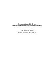
<strong>Wettzell</strong> S/X <strong>Bands</strong> <strong>Cryogenic</strong> <strong>Receiver</strong>2. Cryostat GeometryThe next figures show the cryostat design:Figure 1. Cryostat overview (cold head (light blue), vacuum case (pink and dark blue),radiation shield (red), cold stage (pink) and directional coupler (black)).The cryostat design is an upgrade of a previous one designed at <strong>Wettzell</strong> Observatory severalyears ago. This new design has been performed carefully due to the little free space inside thecryostat and also taking into account the space in the radio telescope at <strong>Wettzell</strong>.The cryostat is built over a CTI Model-22 cold head in a cylindrical dewar made of steel. In thetop cover a vacuum window (<strong>Wettzell</strong> supplied) lets the X band radiation goes through, forthe S band, an N connector feedthrough is used and it is connected to an air line inside thecryostat. In the bottom cover there are all the RF connectors for S and X bands, vacuumflanges, pressure monitor, DC cabling and housekeeping connectors.Inside the cryostat there is a cylindrical radiation shield made of aluminum and withmultilayer isolator (MLI). The temperature of this stage is less than 70 K.Removing the radiation shield, the entire receiver can be easily reached. It is the coldest partof the receiver at temperature of 17 K approximately. The cold stage is made of copper and isconnected to both amplifiers and the directional coupler.All the RF cabling is made of coaxial semi-rigid cable. The cables that connect the cold stage(amplifiers and coupler) with the room temperature stage (SMA connectors) are made ofcoaxial semi-rigid steel cable, UT-085. The cable from the air line output to the S band LNAinput is a coaxial semi-rigid copper cable, UT-141.3
<strong>Wettzell</strong> S/X <strong>Bands</strong> <strong>Cryogenic</strong> <strong>Receiver</strong>Figure 2. Previous dewar design.Figure 3. Cryostat overview (current design).4
<strong>Wettzell</strong> S/X <strong>Bands</strong> <strong>Cryogenic</strong> <strong>Receiver</strong>2.1. Vacuum caseFigure 4. Dewar, vacuum seals and flanges dimensions.The dewar consists of three main parts: stainless steel cylinder, top and bottom covers. At thetop cover the inputs for the X and S bands are presented (vacuum window for X band and Nconnector adapter for S band).The dewar lower flange has several outputs for different uses:- Cold head connection: to place the cold head in the right position, taking into account thelimited space in the 20 m radio telescope at <strong>Wettzell</strong> Observatory, a second flange wasplaced between the lower flange and the cold head. To get the desire vacuum two vitonseals have been used.- Two apertures with transitions for the vacuum control (pressure sensor and vacuumvalve).- Three Fisher hermetic connectors for the housekeeping control and monitoring, andamplifiers biasing.- Four SMA hermetic connectors for the RF input/output signals (calibration and RF).Inside the dewar, at the bottom cover, there is an aluminum plate to carry out the transitionbetween room temperature DC wiring and the cryogenic wires, using DB connectors.5
<strong>Wettzell</strong> S/X <strong>Bands</strong> <strong>Cryogenic</strong> <strong>Receiver</strong>2.1.2. Vacuum WindowThe vacuum window goal is to allow transition (physical, electromagnetic and vacuum)between the X band horn, or the waveguide to the horn, that it is out of the cryostat, and thedirectional coupler.Figure 6. Vacuum window and transition.2.2. Intermediate stage and radiation shieldThe intermediate stage is an aluminum plate of 6 mm thickness and 170 mm diameter,screwed onto the first stage of the cold head. Attached to this plate there is an aluminumcylinder to cover the cold stage and reduce the radiation load. Both parts are covered withmultilayer isolator, MLI (8 layers).Figure 7. Intermediate stage design and radiation shield.On the intermediate stage there are a temperature sensor, a heating resistor, a thermostatand a vacuum trap based on zeolites. These devices have the following characteristics:- Heating resistor: 100 Ω, 25 W.- Zeolites regeneration resistor: the vacuum trap includes a 100 Ω and 2.5 W regeneratorresistor.- Temperature sensor: DT-670 Lakeshore Si-diode.- Thermostat: 70° ± 3°.7
<strong>Wettzell</strong> S/X <strong>Bands</strong> <strong>Cryogenic</strong> <strong>Receiver</strong>Figure 8. Intermediate stage installed in the cryostat (with thethermostat and the heating resistor). Radiation shield with the MLI.Figure 9. Vacuum trap.2.3. Cold stageThe cold stage consists of a copper plate, 8 mm thickness and 63 x 72 mm size. Attached tothis plate are placed the vacuum trap, the thermostat, heating resistor and the temperaturesensor (same specifications than the used for the intermediate stage). The S and X LNAs andthe X band directional coupler are directly attached to this stage.Figure 10. Cold Cu plate design and cold stage with the directional coupler.8
<strong>Wettzell</strong> S/X <strong>Bands</strong> <strong>Cryogenic</strong> <strong>Receiver</strong>2.4. Amplifier setting-upThe cryostat contains two low noise amplifiers:- S Band LNA: Model S-2.3-30 Berkshire Technologies (Ser. 209).- X Band LNA: CITCRYO1-12A.Detailed specifications and biasing information can be found in the appendix.Figure 11. S band low noise amplifier.Figure 12. X band low noise amplifier.2.5. Internal DC wiringThere are 3 hermetic Fischer connectors at the vacuum case:- One of them with 16 pin for monitoring signals and housekeeping.- Two of them with 11 pin for the amplifiers biasing signals.Hermetic Fischer ConnectorC1C2C3FunctionHousekeepingS band LNAX band LNA9
<strong>Wettzell</strong> S/X <strong>Bands</strong> <strong>Cryogenic</strong> <strong>Receiver</strong>The next figures show the Fischer connectors pin-out (11 and 16 pin):Figure 13: 11 pin Fischer(connector view, red point up).Figure 14: 16 pin Fischer(connector view, red point up).Figure 15: LNAs biasing connectors and housekeeping connector.The DC wiring has been done using small section long cables to reduce the conduction load.The next table indicates the pin-out association between connectors.Pin-Out DC connections <strong>Wettzell</strong> S/X receiver:Fischer Pin DB15 Pin Signal1 1 Tc_+2 2 Tc_-3 3 Ti_+4 4 Ti_-5 5 Calef_on6 6 Regen_on7 7 GND_res8 8 (free)9 9 (free)10 10 (free)11 11 (free)Table 2: Fischer Connector (C1) 16 pin (housekeeping) correspondence with the DB15 connector.10
<strong>Wettzell</strong> S/X <strong>Bands</strong> <strong>Cryogenic</strong> <strong>Receiver</strong>Fischer Pin DB9 Pin Signal1 1 Gnd2 2 Vd13 3 Vg14 4 Vd25 5 Vg26 6 Vd37 7 Vg3Table 3: Fischer Connector (C2) 11 pin (S band LNA) correspondence with the DB9 connector.Fischer Pin DB9 Pin Signal1 1 Gnd2 2 Vd3 3 Vg14 4 Vg25 5 (free)6 6 (free)7 7 (free)Table 4: Fischer Connector (C3) 11 pin (X band LNA) correspondence with the DB9 connector.Several pins and wires have been left free taking into account future upgrades (amplifierschanges).Figure 16: DC wiring.2.5.1. Low Noise Amplifiers biasing wiringBand Amplifier frequency range (GHz) IVS Frequencies (GHz) PurposeS 2.1-2.4 2.2-2.37 Geodetic VLBIX 1-12 8.15-9.0 Geodetic VLBI11
<strong>Wettzell</strong> S/X <strong>Bands</strong> <strong>Cryogenic</strong> <strong>Receiver</strong>Next figures show the pin-out for the amplifier biasing connectors:Figure 17. Pin-out biasingconnector X band amplifier.Figure 18. Pin-out biasing connector S band amplifier.2.5.2. Housekeeping wiringThere is a 16 pin Fischer connector placed at the room temperature stage (300 K) for thecryostat internal monitoring signals: heating resistors, zeolites regenerators, temperaturesensors and thermostats.Fischer Pin Signal Description1 Tc_+ Cold stage temperature sensor (+)2 Tc_- Cold stage temperature sensor (-)3 Ti_+ Intermediate stage temperature sensor (+)4 Ti_- Intermediate stage temperature sensor (-)5 Calef_onSignal to activate the heatersafter passing through the thermostat6 Regen_onSignal to activate the zeolites regenerationresistor after passing through the thermostat7 GND_res GroundTable 5. Housekeeping signals description.A five meters cable is supplied to connect the receiver with the different housekeepingsignals. One end has the Fischer connector o be plugged to the receiver. The other endcontains the following elements:12
<strong>Wettzell</strong> S/X <strong>Bands</strong> <strong>Cryogenic</strong> <strong>Receiver</strong>Fischer Pin Signal DB 25 pin Banana Connectors1 Tc_+ 3, 42 Tc_- 15, 163 Ti_+ 6, 74 Ti_- 18, 195 Calef_on Red6 Regen_on Yellow7 GND_res BlackTable 6. Housekeeping 5 m cable description.- DB-25 connector: to Lakeshore 218 system (positions one and two) DT 670 sensors.- Banana connector: to power supply for the receiver heating and zeolites regenerating.13
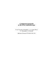
<strong>Wettzell</strong> S/X <strong>Bands</strong> <strong>Cryogenic</strong> <strong>Receiver</strong>3. <strong>Cryogenic</strong> systemThis receiver uses a CTI-<strong>Cryogenic</strong>s Cold Head Model 22, with the following characteristics:Figure 19. Typical refrigeration capacity of the model 22C cryodyne cryocooler (50 Hz).14
<strong>Wettzell</strong> S/X <strong>Bands</strong> <strong>Cryogenic</strong> <strong>Receiver</strong>4. Cryostat thermal and vacuum behaviorSeveral tests have been performed to determine the cryostat thermal and vacuum behavior.The systems used for cooling and pumping are the following:- Cold head CTI 22.- Compressor CTI model 8200, 220 V, 50 Hz.- Vacuum system:Rotary pump and turbomolecular pump Alcatel.Vacuum sensors: Pirani sensor (pressure from atmospheric to 10 -4 mbar) and coldcathode (pressure from 10 -4 mbar to 10 -8 mbar).The final results are:- Intermediate stage temperature: ≤ 63 K.- Cold stage temperature: ≤ 17 K.- Vacuum
<strong>Wettzell</strong> S/X <strong>Bands</strong> <strong>Cryogenic</strong> <strong>Receiver</strong>Figure 21. Cooling test 2.Figure 22. Intermediate stage load ≈4 W, cold stage load ≈1 W.16
<strong>Wettzell</strong> S/X <strong>Bands</strong> <strong>Cryogenic</strong> <strong>Receiver</strong>Figure 23. Vacuum test (Pirani sensor) and thermal behavior during the vacuum test,(zeolites regenerators and heating resistors on during the first 5 hours).17
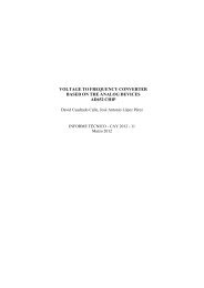
<strong>Wettzell</strong> S/X <strong>Bands</strong> <strong>Cryogenic</strong> <strong>Receiver</strong>5. <strong>Receiver</strong> calibration: noise temperature and gainThe Y factor method has been used to calibrate the receiver (measure the noise temperature).The noise temperature measurement is carried out connecting the receiver input to differentadapted loads with known temperatures.When the load at the input has a temperature, T H, the power at the output is P H, hot load. If asecond measure is done with a load with a different temperature, T C, the power will bedifferent, P C, cold load. Then, the receiver noise temperature can be calculated by thefollowing expressions:This method is based on the hypothesis that the receiver behavior is linear between P H andP C.The thermal loads used are:- Hot load: coaxial SMA 50 Ω load at room temperature, ≈ 298 K.- Cold load: coaxial SMA 50 Ω load submerged in liquid nitrogen, ≈ 77 K.Results without taking into account the losses due to the cables, SMA connectors, waveguidetransition, etc.:LNAs Noise Temperature measured at room temperatureT H= = 295.5 KFreq. (GHz)X bandT C = 77.3 KNoise Temp. (K)8 75.5558.1 81.578.2 75.1558.3 70.4358.4 69.928.5 84.288.6 88.0758.7 82.8958.8 75.1658.9 73.149 85.595T H= = 296 KFreq. (GHz)S bandT C = 77.3 KNoise Temp. (K)2 59.982.1 59.7852.2 52.6452.3 52.1052.4 61.6352.5 49.152.6 57.9652.7 58.162.8 79.8552.9 77.9453 80.37518
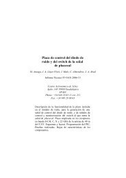
<strong>Wettzell</strong> S/X <strong>Bands</strong> <strong>Cryogenic</strong> <strong>Receiver</strong>Figure 24. TRX at room temperature (≈ 295 K).LNAs Noise Temperature and Gain measured at cold temperatureT H = 295 KFreq. (GHz)X bandT C = 77.3 KNoise Temp. (K)8 12.1558.1 11.0458.2 12.358.3 13.5158.4 11.98.5 12.3758.6 12.628.7 11.658.8 11.668.9 11.649 12.67T H= = 296 KFreq. (GHz)S bandT C = 77.3 KNoise Temp. (K)2.2 7.952.3 9.782.4 10.712.5 5.83519
<strong>Wettzell</strong> S/X <strong>Bands</strong> <strong>Cryogenic</strong> <strong>Receiver</strong>Freq. (GHz)X bandGain (dB)8 33.138.1 33.178.2 33.348.3 33.38.4 33.138.5 33.28.6 33.138.7 32.978.8 33.178.9 339 32.8Freq. (GHz)S bandGain (dB)2.2 31.632.3 30.972.4 31.032.5 30.63Figure 25. TRX and gain at cold temperature (≈ 16.5 K).20
<strong>Wettzell</strong> S/X <strong>Bands</strong> <strong>Cryogenic</strong> <strong>Receiver</strong>Figure 27. PC Board Components.22
<strong>Wettzell</strong> S/X <strong>Bands</strong> <strong>Cryogenic</strong> <strong>Receiver</strong>7. Installation, first use and switch offProceed as follow to install de receiver:- The vacuum controller, the temperature monitor, the LNAs biasing module and the RFmodule must be switch off.- Making VacuumConnect the housekeeping cable to the rear side Fischer connector of the cryostat(C1) (figure 15).Connect the vacuum controller to the vacuum sensor Quadmag.Connect the vacuum valve to the corresponding vacuum flange (the valve must beclosed).Switch on the vacuum controller. The vacuum sensor will start the set up and a greenled will light continuously when ready. The vacuum controller will show atmosphericpressure.Switch on the temperature monitor (housekeeping cable has a DB25 connector for theLakeshore connector input). The temperature of the first 2 channels will be aroundroom temperature.Connect a vacuum system (rotary pump and turbomolecular) to the DN25 output ofthe vacuum valve.Start running the rotary pump for at least ten minutes.Slowly open the valve. The vacuum level will start to decrease. If the decreasing of thepressure inside the cryostat stops then open slowly the valve. Repeat this procedureuntil you open completely the valve. During this procedure avoid any abrupt openingof the valve. When the vacuum is about 10 -1 mbar, start turbomolecular operation.Connect the zeolites regenerator banana connector to a power supply.• Black: GND• Red:+6.17 V, 113 mAConnect the heating resistor banana connectors to a power supply.• Black: GND• Yellow: +25.7 V, 493 mALeave the system running in the above conditions for 12 hours. Then, the resistor canbe turned off. The vacuum system should be pumping at least for 12 hours more.- Connecting the helium compressorRemove all dust plugs and caps from the helium supply and return lines, compressorand cold head. Check all fittings.Connect the helium return line between the compressor and the cold head.Connect the helium supply line between the compressor and the cold head.Verify proper helium supply static pressure (245 psi for CTI 8200 compressor). If theindicated pressure is not the specified by the compressor manufacturer follow theinstructions supplied by the manufacturer.Connect the cold head cable between the compressor and the cold head.23
<strong>Wettzell</strong> S/X <strong>Bands</strong> <strong>Cryogenic</strong> <strong>Receiver</strong>Figure 28. <strong>Wettzell</strong> cryostat vacuum and cold test.- Connecting the LNAs Biasing UnitConnect the LNAs Biasing Module to a power supply (+15 V, -15 V, GND). Powersupply off.Plug the 2 DC supply cables between the LNAs Biasing Module and the Cryostatconnector plate (figure 15).Cryostat ConnectorC2C3LNA Biasing ModuleS band LNAX band LNAThe LNAs biasing point is already set up. In case a verification or change is needed goto chapter 6.Turn on the power supply (verify table 7 values).- First useAfter 24 hours pumping the system is ready to start the cooling down process.The pressure inside should be at 5·10 -3 mbar or lower. Close the vacuum valve. The pressure inside the cryostat will increase slightly at 10 -6mbar/s rate or lower (faster just when closing the vacuum valve). The pressure insidemust be maintained always below 5·10 -2 mbar.Switch on the compressor. The temperatures will start decreasing and also thepressure level.After 8-9 hours the cryostat will reach its operational cryogenic temperature andpressure.Temperature radiation shieldTemperature cold stagePressure< 70 K< 20 K< 10 -6 mbar24
<strong>Wettzell</strong> S/X <strong>Bands</strong> <strong>Cryogenic</strong> <strong>Receiver</strong>- Switch offFor switching off the system (for example if the system will be stored for long periods or formaintenance) proceed as follows:Be sure that the pumping valve is closed.Switch off the compressor.Switch off the LNAs Biasing Module.Leave the cryostat warming to room temperature. This can be verified at thetemperature monitor. This process can be accelerated by turning on the heatingresistors (+25 V) and the zeolites regenerators (+6 V).Once the system is at room temperature, open slowly the vacuum valve to achieveatmospheric pressure inside the cryostat.25
<strong>Wettzell</strong> S/X <strong>Bands</strong> <strong>Cryogenic</strong> <strong>Receiver</strong>8. References[1] Behrens, G., Campbell, W., Williams, D., White, S.. Guidelines for de Design of <strong>Cryogenic</strong>Systems. National Radio Astronomy Observatory (NRAO), Green Bank, West Virginia.1997.[2] CTI-<strong>Cryogenic</strong>s cryodyne refrigeration systems. Helix Techonology Corporation, 2002,USA.[3] DT-670 Sensor Catalog. Lakeshore. (http://www.lakeshore.com/Documents/LSTC_DT670_l.pdf)[4] Juntas tóricas. Epidor Catalog (O-rings).[5] López, J.A., Gallego, J.D., de Vicente, P., Abad, J.A., Almendros, C. Criostato del receptorS/X de VLBI del CAY. Informe técnico IT OAN 1994-6.[6] Malo, I., López Fernández, J. A., Tercero, F., Abad, J.A., Almendros, C., Fernández, J.,Yagüe, J.M.. Criostato del receptor de GHz del CAY. Informe técnico IT OAN 2005-12.[7] Multiple Uses of Model 22C/350C Cryodyne® Refrigerators Installation, OperationandServicing Instructions. Brooks. USA.[8] Serna Puente, J. M., López Fernández, J. A., López Pérez, J. A., Tercero, F., et al. Nuevoreceptor banda C de la antena Aries del Observatorio de Yebes. Informe técnico IT OAN2010-14.[9] Serna Puente, J. M., López Fernández, J. A., Tercero, F., et al. Receptor criogénico bandasK/Q de la Antena Aries del Centro de Desarrollos Tecnológicos de Yebes. Informe técnicoIT OAN 2013.26
<strong>Wettzell</strong> S/X <strong>Bands</strong> <strong>Cryogenic</strong> <strong>Receiver</strong>9. Appendix9.1. S band amplifier specifications27
28<strong>Wettzell</strong> S/X <strong>Bands</strong> <strong>Cryogenic</strong> <strong>Receiver</strong>
<strong>Wettzell</strong> S/X <strong>Bands</strong> <strong>Cryogenic</strong> <strong>Receiver</strong>9.2. X band amplifier specifications29
30<strong>Wettzell</strong> S/X <strong>Bands</strong> <strong>Cryogenic</strong> <strong>Receiver</strong>
31<strong>Wettzell</strong> S/X <strong>Bands</strong> <strong>Cryogenic</strong> <strong>Receiver</strong>
<strong>Wettzell</strong> S/X <strong>Bands</strong> <strong>Cryogenic</strong> <strong>Receiver</strong>9.3. Temperature sensors specifications32
<strong>Wettzell</strong> S/X <strong>Bands</strong> <strong>Cryogenic</strong> <strong>Receiver</strong>9.4. Gain and Coupling RF MeasurementsMeasurements carried out at room temperature.X Band LNAFrequency(Ghz)Pout_cable(dBm)Pout_ampli(dBm)Pout_coupling(dBm)Gain (dB)Coupling(dB)8 -40.17 -16.83 -47.17 23.34 -30.348.05 -40 -17 -47.33 23 -30.338.1 -40.33 -17 -47 23.33 -308.15 -40.17 -17.17 -46.83 23 -29.668.2 -41 -17 -46.83 24 -29.838.25 -40.33 -16.67 -46.67 23.66 -308.3 -40.33 -16.5 -46.5 23.83 -308.35 -40.17 -16.83 -46.33 23.34 -29.58.4 -40 -16.67 -46.17 23.33 -29.58.45 -40 -16.83 -46.17 23.17 -29.348.5 -40.17 -16.67 -46.17 23.5 -29.58.55 -40.17 -16.67 -46.17 23.5 -29.58.6 -40.17 -16.83 -45.67 23.34 -28.848.65 -40.33 -16.83 -45.5 23.5 -28.678.7 -40.17 -16.5 -45.33 23.67 -28.838.75 -40.33 -16.67 -45.67 23.66 -298.8 -40.33 -16.5 -45.5 23.83 -298.85 -40.5 -16.67 -45.33 23.83 -28.668.9 -40.5 -16.83 -45.33 23.67 -28.58.95 -40.67 -16.83 -45.67 23.84 -28.849 -40.5 -17.17 -46 23.33 -28.8333
<strong>Wettzell</strong> S/X <strong>Bands</strong> <strong>Cryogenic</strong> <strong>Receiver</strong>S Band LNAFrequency(Ghz)Pout_cable(dBm)Pout_ampli(dBm)Pout_coupling(dBm)Gain(dB)Coupling(dB)2.1 -40.67 -10.33 -40.83 30.34 -30.52.15 -40.5 -10.83 -41.17 29.67 -30.342.2 -40.5 -11 -41.5 29.5 -30.52.25 -40.5 -11.17 -41.67 29.33 -30.52.3 -40.67 -11.5 -41.83 29.17 -30.332.35 -40.33 -11.17 -41.67 29.16 -30.52.4 -40.33 -11.5 -42 28.83 -30.52.45 -40.33 -11.67 -42.5 28.66 -30.832.5 -40.33 -12 -43.33 28.33 -31.332.55 -40.5 -12.17 -43.83 28.33 -31.6634
<strong>Wettzell</strong> S/X <strong>Bands</strong> <strong>Cryogenic</strong> <strong>Receiver</strong>9.5. RF MeasurementsAirline S parameters.Vacuum window S parameters.35