Development of Pneumatic Channel Wing ... - CAFE Foundation
Development of Pneumatic Channel Wing ... - CAFE Foundation
Development of Pneumatic Channel Wing ... - CAFE Foundation

Create successful ePaper yourself
Turn your PDF publications into a flip-book with our unique Google optimized e-Paper software.
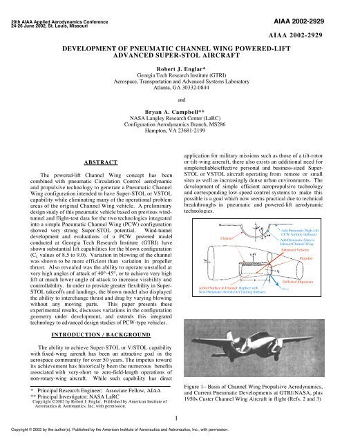
20th AIAA Applied Aerodynamics Conference24-26 June 2002, St. Louis, MissouriAIAA 2002-2929AIAA 2002-2929DEVELOPMENT OF PNEUMATIC CHANNEL WING POWERED-LIFTADVANCED SUPER-STOL AIRCRAFTRobert J. Englar*Georgia Tech Research Institute (GTRI)Aerospace, Transportation and Advanced Systems LaboratoryAtlanta, GA 30332-0844andBryan A. Campbell**NASA Langley Research Center (LaRC)Configuration Aerodynamics Branch, MS286Hampton, VA 23681-2199ABSTRACTThe powered-lift <strong>Channel</strong> <strong>Wing</strong> concept has beencombined with pneumatic Circulation Control aerodynamicand propulsive technology to generate a <strong>Pneumatic</strong> <strong>Channel</strong><strong>Wing</strong> configuration intended to have Super-STOL or VSTOLcapability while eliminating many <strong>of</strong> the operational problemareas <strong>of</strong> the original <strong>Channel</strong> <strong>Wing</strong> vehicle. A preliminarydesign study <strong>of</strong> this pneumatic vehicle based on previous windtunneland flight-test data for the two technologies integratedinto a simple <strong>Pneumatic</strong> <strong>Channel</strong> <strong>Wing</strong> (PCW) configurationshowed very strong Super-STOL potential. Wind-tunneldevelopment and evaluations <strong>of</strong> a PCW powered modelconducted at Georgia Tech Research Institute (GTRI) haveshown substantial lift capabilities for the blown configuration(C L values <strong>of</strong> 8.5 to 9.0). Variation in blowing <strong>of</strong> the channelwas shown to be more efficient than variation in propellerthrust. Also revealed was the ability to operate unstalled atvery high angles <strong>of</strong> attack <strong>of</strong> 40°-45°, or to achieve very highlift at much lower angle <strong>of</strong> attack to increase visibility andcontrollability. In order to provide greater flexibility in Super-STOL take<strong>of</strong>fs and landings, the blown model also displayedthe ability to interchange thrust and drag by varying blowingwithout any moving parts. This paper presents theseexperimental results, discusses variations in the configurationgeometry under development, and extends this integratedtechnology to advanced design studies <strong>of</strong> PCW-type vehicles.application for military missions such as those <strong>of</strong> a tilt-rotoror tilt-wing aircraft, there also exists an additional need forsimple/reliable/effective personal and business-sized Super-STOL or VSTOL aircraft operating from remote or smallsites as well as increasingly dense urban environments. Thedevelopment <strong>of</strong> simple efficient aeropropulsive technologyand corresponding low-speed control systems to make thispossible is a goal which now seems practical due to technicalbreakthroughs in pneumatic and powered-lift aerodynamictechnologies.<strong>Channel</strong>Airfoil Surface in <strong>Channel</strong>; Replace withNew <strong>Pneumatic</strong> Airfoils/Aft Turning SurfacesAdd <strong>Pneumatic</strong> High-LiftCCW Airfoils OutboardAdd <strong>Pneumatic</strong> Slots toInboard <strong>Channel</strong> <strong>Wing</strong>Enhanced VelocityPropellerDeflected SlipstreamV d BlownINTRODUCTION / BACKGROUNDThe ability to achieve Super-STOL or V/STOL capabilitywith fixed-wing aircraft has been an attractive goal in theaerospace community for over 50 years. The impetus towardits achievement has historically been the numerous benefitsassociated with very-short to zero-field-length operations <strong>of</strong>non-rotary-wing aircraft. While such capability has direct__________________________________________________* Principal Research Engineer; Associate Fellow, AIAA** Principal Investigator; NASA LaRCCopyright ©2002 by Robert J. Englar. Published by American Institute <strong>of</strong>Aeronautics & Astronautics, Inc. with permission.Figure 1– Basis <strong>of</strong> <strong>Channel</strong> <strong>Wing</strong> Propulsive Aerodynamics,and Current <strong>Pneumatic</strong> <strong>Development</strong>s at GTRI/NASA, plus1950s Custer <strong>Channel</strong> <strong>Wing</strong> Aircraft in flight (Refs. 2 and 3)Copyright © 2002 by the author(s). Published by the American Institute <strong>of</strong> Aeronautics and Astronautics, Inc., with permission.1
Two promising technologies to evolve from earlierSTOL/VSTOL research are the Custer <strong>Channel</strong> <strong>Wing</strong> poweredliftconfiguration and the Circulation Control <strong>Wing</strong> (CCW)pneumatic high-lift concept. Through innovative use <strong>of</strong> thepropeller slipstream, the <strong>Channel</strong> <strong>Wing</strong> airplane developed byWillard Custer (Refs. 1, 2, 3) was able to achieve significantlift coefficient and efficient downward thrust deflection withoutvarying the high-lift configuration geometry. This poweredlifttechnology, tunnel-tested by NACA in 1953, (Ref. 1) andthen flight-tested and further developed by Custer in the late1950’s (Ref. 2), employed the concept shown in the sketch <strong>of</strong>Figure 1 (from Ref. 3). In essence, the propeller located at thevery trailing edge <strong>of</strong> the 180°-arc circular channel in the wingfurther increased the velocity over the channel’s upper surfaceand augmented the circulation and lift there in much the samemanner as a flap, but perhaps to a greater extent. Lift was alsoaugmented by the deflected slipstream behind the channel suchthat∆CL = CT sin ( α + δslipstream )However, while in-flight lift coefficients nearing 5 weregenerated by thrust coefficients also nearing 5 (Ref. 3), theflight-tested Custer <strong>Channel</strong> <strong>Wing</strong> aircraft demonstrated anumber <strong>of</strong> drawbacks associated with low-speed handling,cruise drag, stability & control, high-incidence operation, andone-engine-out scenarios, including:• much <strong>of</strong> the high CL was from redirected thrust, less wasfrom circulation lift augmentation• high drag could result from the channel’s surface area• asymmetric thrust yields asymmetric moments &instability• channel leading-edge and trailing-edge separation couldoccur at high angle <strong>of</strong> attack, α• poor low-speed control from conventional aerodynamicsurfaces at low speeds• nose-down pitch from aft propeller loading on the wing• non-uniform flow around the prop at high α• poor lift/drag ratio• high-angle-<strong>of</strong>-attack operation could cause poor visibilityand control• one-engine-out control problemsTo alleviate these shortcomings, preliminary research hasbeen accomplished under a NASA-Langley-sponsored programat Georgia Tech Research Institute (GTRI) which isinvestigating adapting Circulation Control pneumatictechnology (Refs. 4 and 5, for example) to dramaticallyimprove the <strong>Channel</strong> <strong>Wing</strong> configuration. As Figure 1suggests, the new pneumatic configuration thus developedcombines blowing on curved surfaces at the channel trailingedge to greatly augment the lift and thrust deflection withoutusing high angle <strong>of</strong> attack. It also employs blown CirculationControl <strong>Wing</strong> technology on the outboard wing panels t<strong>of</strong>urther augment lift and low-speed controllability whileproviding additional drag when needed for slow-speedapproaches down steep glide slopes for Super-STOL. Based onearlier CCW/Upper Surface Blowing (USB) wind-tunnel andfull-scale data (Refs. 6 and 7) and CCW flight test data from anFig. 2 – Previously Developed Circulation Control <strong>Wing</strong>/Upper Surface Blowing Powered-Lift Concept (Ref. 6)A-6 STOL-demonstrator program (Ref. 8), the predicted liftand drag capabilities for the <strong>Pneumatic</strong> <strong>Channel</strong> <strong>Wing</strong>configuration were expected to <strong>of</strong>fer great Super-STOLpromise. Reference 9 details these early predictions before thecurrent wind-tunnel test data were available.Figure 2 shows the CCW/USB concept, wheretangential blowing on a highly curved trailing edge augmentsflow field entrainment, increases circulation and deflects thrustto add more incremental lift. Thrust deflection angles <strong>of</strong> 165°caused by blowing were measured experimentally on windtunnelmodels (Refs. 5 and 6). This concept providespneumatic STOL, VSTOL and thrust-reversing capabilitieswithout any moving parts. CCW alone employs a similartangential-blowing configuration but without the pneumaticthrust deflection. CCW airfoils have generated measured 2-Dlift augmentations <strong>of</strong> 80 times the input blowing momentum(Refs. 4 and 5). When flight-tested on an A-6 flightdemonstrator, CCW showed a 140% increase in useable highlift,employing only half <strong>of</strong> the available bleed air from theaircraft’s standard turbojet engines (Ref. 8). Figure 1 showshow these blown flow-entrainment devices would be arrangedto enhance the effectiveness <strong>of</strong> the <strong>Pneumatic</strong> <strong>Channel</strong> <strong>Wing</strong>(PCW) configuration. In addition, the CCW lift capability canbe applied differentially outboard to generate very large rollingand yawing moments which are essential for controlled flightat very low Super-STOL speeds. Powered lift coefficients upto 15 were predicted to result for the blown channel wingsection, with an additional 4 to 5 possible from the outboardCCW (Ref. 9). For comparison, the Custer <strong>Channel</strong> <strong>Wing</strong>aircraft generated CL just under 5; a conventional slotted flap2
on this wing geometry would generate CL from 2 to 3. Initialtake<strong>of</strong>f predictions (Ref. 9) showed that these PCWcapabilities could produce hot-day take<strong>of</strong>f ground rolls <strong>of</strong> under100 ft for typical mission weights, and even zero ground rollunder certain conditions.As part <strong>of</strong> an ongoing program for NASA LangleyResearch Center to develop this <strong>Pneumatic</strong> <strong>Channel</strong> <strong>Wing</strong>concept, GTRI and NASA have teamed in an experimentaldevelopment program being conducted at GTRI, and haveprovided aerodynamic and propulsive data input for designstudies being conducted at both NASA and GTRI. Thiscurrent AIAA paper will present these experimental results anddiscuss effects deriving from variations in PCW geometry,propeller thrust and channel blowing.EXPERIMENTAL APPARATUS ANDTEST TECHNIQUESA wind-tunnel development/evaluation program wasconducted at GTRI on a generic twin-engine Super-STOL-typetransport configuration, Figure 3, using the 0.075-scale semispanmodel shown in Figure 4. Here, a variable–speed electricmotor was installed in the nacelle, which could be located atvarious positions in the channel, and which drove 2-bladed or3-bladed propellers <strong>of</strong> various diameters and pitch. Alsovariable was the height <strong>of</strong> the blowing slot located at 95% <strong>of</strong>the channel chord length, as well as the blowing momentumcoefficient and portions <strong>of</strong> the slot arc length which wereblown. Behind the slot, the rounded trailing edge curved only90° (rather than the more conventional 180° <strong>of</strong> typical CCWconfigurations) for an anticipated maximum thrust deflection<strong>of</strong> around 90° plus α. It was already known (Fig. 2) thatthrust deflections up to 165° were a possibility. Here, themomentum coefficient is defined asC µ = (mass flow rate * jet velocity) / (dynamic pressure *wing planform area) = m Vj / (qS).Fig. 3 – Conceptual <strong>Pneumatic</strong> <strong>Channel</strong> <strong>Wing</strong> Super STOLTransport ConfigurationRemovable Motor/PropLong. Prop Variation<strong>Pneumatic</strong> <strong>Channel</strong>, Aft SlotRemovable SponsonGeneric Transport FuselageCenterline, Mount on Floor BalanceAdd-on HorizontalStabilizer Location2-Slotted CC <strong>Wing</strong>,Variable CCW FlapHalf-span Powered <strong>Pneumatic</strong> <strong>Channel</strong> <strong>Wing</strong> Modelwith 3 Air Blowing Slots per wing (1 in <strong>Channel</strong>, 2 in CCW)<strong>Pneumatic</strong> <strong>Channel</strong> <strong>Wing</strong> Model Mounted on Floor Balancein the GTRI Model Test Facility3 HP Electric Motor andPropeller Calibration SetupThis semi-span model configuration was mounted on anunder-floor balance with air supply and automated pitch tablein the GTRI Model Test Facility 30” x 43” x 90” test section.Tunnel wall boundary layer near the test section floor waseliminated by use <strong>of</strong> tangential floor blowing. In a follow-onversion <strong>of</strong> this configuration, both the leading edge and thetrailing edge <strong>of</strong> the outboard CCW wing section will beblown. For the Phase I data to be presented herein, theoutboard wing remained unblown with no leading- or trailingedgeflap deflections. Therefore the emphasis in the followingdata is on the performance <strong>of</strong> the inboard blown <strong>Pneumatic</strong><strong>Channel</strong> <strong>Wing</strong> configuration.WIND-TUNNEL EVALUATIONS and RESULTSTest techniques employed in the subsonic tunnelevaluation <strong>of</strong> this pneumatic powered-lift model are similar tothose employed and described in Refs 10 and 11 for blownairfoil and semi-span models, except that special additionaltechniques were employed to account for the installation <strong>of</strong> theactive propeller in the channel (see below). Some 196 wind-Fig. 4 – <strong>Pneumatic</strong> <strong>Channel</strong> <strong>Wing</strong>/CCW Semi-span ModelDesign, Power Unit, and Installation in GTRI Model TestFacility Research Tunnel (Outboard CCW Unblown Here)3
tunnel runs were conducted during the present test program atGTRI (including propeller calibrations) to develop theseblown-configuration geometries and to evaluate their aeropropulsivecharacteristics. A typical run consisted <strong>of</strong> a sweep(incremental variation) <strong>of</strong> prop thrust or blowing pressure atconstant angle <strong>of</strong> attack and wind speed. Also, angle <strong>of</strong> attacksweeps or dynamic pressure (velocity) sweeps were run atconstant thrust and blowing coefficients, CT and Cµ. Typicaltest results are presented in the following sections todemonstrate how these various parameters affected overallperformance.4.03.53.02.52.0Propeller OFF, Nacelle ON, q=10 psfSlot Arc=160°, h=0.01", Wheel Sponson OnCµ=0.05Cµ=0.10Cµ=0.20Cµ=0.30C L0.0 0.1 0.2 0.3 0.4 0.5 0.6 0.7 0.8 0.9 1.0 1.1Tunnel Test ResultsIn Figures 5a and 5b are shown the effects on lift and dragcoefficients <strong>of</strong> blowing the channel trailing edge without theprop installed (i.e., CT=0), but with the engine nacelle inplace. Notice the ability <strong>of</strong> the blowing to more than doublethe CLmax <strong>of</strong> the unblown configuration with virtually noreduction in the stall angle, αstall . The CL values shown arecomparable to or greater than those which would normally begenerated by more-complex moving mechanical flaps. Noticealso the ability <strong>of</strong> the blowing at α = 0° to increase CL by afactor <strong>of</strong> nearly 10 over the unblown value. At α = 0°,blowing at Cµ=0.30 yields 50% more CL than the CLmax <strong>of</strong>the unblown configuration. In Figure 5b, the drag polars atconstant Cµ are typically quadratic in CL. Below where thestall begins, they follow essentially the same single curve,using blowing to progress to each successive higher CLregion.Addition <strong>of</strong> the propeller to the channel brings intoplay the powered-lift characteristics <strong>of</strong> the <strong>Pneumatic</strong> <strong>Channel</strong>1.51.00.50.0-0.5Cµ=0.0Fig. 5b – Measured Blown Drag <strong>of</strong> <strong>Pneumatic</strong> <strong>Channel</strong><strong>Wing</strong> Model Without the Propeller Installed<strong>Wing</strong> configuration. Figure 6, for α = 0°, shows thevariations in CL and CD with thrust coefficient CT for fixedvalues <strong>of</strong> blowing coefficient. Here, in order to recognize thedirect thrust component to lift and drag, thrust coefficient isdefined as C T = T/(qS), where T is the calibrated uninstalledwind-on prop-alone (not-in-the-channel) thrust at the properadvance ratio, i. e., representative test dynamic pressure, q.C D4.03.5Propeller OFF, Nacelle ON, q=10 psfSlot Arc=160°, h=0.01", Wheel Sponson OnCµ=0.308.58.07.57.06.52-Bladed Prop 6 at Location x=0.60c,0.02" Prop Gap, Wheel Pod On, α geo =0°,h slot =0.01", No Outboard Blowing,160° Blown <strong>Channel</strong> Arc, q=2.5 psf3.02.52.0Cµ=0.20Cµ=0.10Cµ=0.05C Lor6.05.55.04.54.03.5C LCµ=1.0Cµ=0.33.01.52.52.0Cµ=0.11.0Cµ=0.01.51.0Cµ=0.0C L-5 0 5 10 15 20 25 300.50.50.0-0.50.0-0.5-1.0-1.5-2.0-2.5C DC D-0.0 0.2 0.4 0.6 0.8 1.0 1.2 1.4 1.6 1.8 2.0 2.2 2.4Cµ=0.3Cµ=0.1Cµ=0.0Cµ=1.0Angle <strong>of</strong> Attack, , degFig. 5a– Measured Blown Lift Capability <strong>of</strong> <strong>Pneumatic</strong><strong>Channel</strong> <strong>Wing</strong> Model Without the Propeller Installed<strong>Channel</strong> <strong>Wing</strong> C TFig. 6– GTRI Test Results: Prop Thrust Effects on Lift andDrag at Constant Blowing and α=0°4
8.58.07.57.0C LC T =2.2C T =1.6C T =1.09.08.58.07.5C T =2.2,Cµ=1.0C Lor6.56.05.55.04.54.03.53.02.52.01.51.00.50.0-0.5-1.0C DC T =0.0, No Prop2-Blade Prop 6, x=0.60c Location,0.02" Prop Gap,Wheel Pod On, α=10°,hslot=0.01 ", No Outboard Blowing;160° Blown <strong>Channel</strong> Arc, q=2.5 psfC T =0.0, No PropC T =1.0C T =1.6C T =2.27.06.56.05.55.04.54.03.53.02.52.01.51.00.50.0C T =2.2,Cµ=0.3 C T =1.6,Cµ=0.3C T =1.6,Cµ=0.1C T =1.6,Cµ=0.02-Blade Prop 6, x=0.95c Location,Wheel Pod On, 160° <strong>Channel</strong> Slot,hslot=0.01", q=2.5 psf,No Outboard BlowingProp Off,Nacelle On,CT=0, Cmu=0.0C L-5 0 5 10 15 20 25 30 35 40 45 50C D0.0 0.2 0.4 0.6 0.8 1.0 1.2 1.4 1.6 1.8 2.0 2.2 2.4-1.5-0.5-2.0-2.5Angle <strong>of</strong> Attack, , deg<strong>Channel</strong> <strong>Wing</strong> CFig. 7 – Blowing Variation Effects on Lift and Drag atConstant CT and α=10°1.61.41.21.0The reference area S is the wing semi-planform area. Thesethrust values were determined prior to installation in thechannel by testing the prop alone in the tunnel at variousRPMs and tunnel speeds. Then, calibration curves <strong>of</strong> T vsRPM were input to the data reduction program at given testwind speeds. Thus CT, CL and CD are directly comparable ona common reference basis to determine force contributionsfrom installed thrust. This avoids the difficulty which wouldbe caused by using the standard helicopter thrust coefficient,which is based on rotor (or prop) geometry rather than wingarea. Also, note that measured CD thus obviously includesthe input thrust, which cannot reasonably be separated fromthe aerodynamic drag alone once the prop is in the channel.Measured CD can thus be negative. After the initial lowvalues <strong>of</strong> CT are exceeded, CL increases nearly linear with CT,and CD reduces nearly linearly.Figure 7 shows that incremental lift augmentationdue to blowing is much greater than due to CT (from Figure6). Here at CT = 2.2, the blown configuration generates CLaround 8.5 at α =10°. The flight-tested Custer <strong>Channel</strong> <strong>Wing</strong>(Ref. 3) generated CL = 3.1 at this CT, but required α = 24°-25°. Note also that increased blowing at a constant CT yieldsincreased drag (rather than thrust recovery) which can be quiteessential for Super-STOL approaches and landings. These liftcomparisons in Figures 6 and 7 show that lift increases moreefficiently by increasing blowing than by increasing thrust. Inthe Figure 8 plot is shown the variation in lift and drag with0.80.60.4CT=0, Cµ=0.0,No PropC D0.20.0-0.2CT=2.2, Cµ=1.0CT=1.6, Cµ=0.3-0.4-0.6CT=1.6, Cµ=0.1-0.8-1.0-1.2CT=1.6, Cµ=0.0-1.4CT=2.2, Cµ=0.3-1.6-1.8-5 0 5 10 15 20 25 30 35 40Angle <strong>of</strong> Attack, , degFig. 8 – Effects <strong>of</strong> Blowing and CT on Lift Coefficient, StallAngle and Drag Coefficientangle <strong>of</strong> attack for the blown powered configuration incomparison to the unblown baseline configuration without theprop. Here, flow visualization showed that the initial stall(α=15°-17°) seen for most <strong>of</strong> the lift curves corresponded tostall <strong>of</strong> the outboard unblown wing section, while the blownchannel wing section then continued on to stall angles <strong>of</strong> 40°-45° and C L values <strong>of</strong> 8.5 to 9. Notice that CD includingthrust increases from negative to positive values as incidenceincreases.5
7.06.56.05.5x/c=0.80x/c=0.60x/c=0.95C T =2.2C T=1.05.04.5x/c=0.60C T=0.0, No Prop,Nacelle On4.0C L0.0 0.2 0.4 0.6 0.8 1.0 1.2 1.4 1.6 1.8 2.0 2.2 2.43.5x/c=0.803.0Prop x/c=0.60c2.52.0x/c=0.951.51.00.52-Blade Prop 6, 0.02" Prop Gap,Wheel Pod On, α geo=0°, h slot=0.01",No Outboard Blowing; q=2.5 psf0.0<strong>Channel</strong> <strong>Wing</strong> C9.08.58.0Prop x/c =0.60C T =2.2,Cµ=1.07.57.06.5α geo =0°0.60Prop x/c =0.95C T =2.2,Cµ=0.3Prop x/c = 0.95c6.05.50.95C T =2.2,Cµ=0.0Fig. 9 – Installed Semi-span <strong>Pneumatic</strong> <strong>Channel</strong> <strong>Wing</strong> Modelwith Variable Prop/Nacelle Locations5.04.54.0C L-5 0 5 10 15 20 25 30 35 40 45 500.60A series <strong>of</strong> evaluations was run to investigatevariation in PCW configuration geometry. Figure 9 showsthe range <strong>of</strong> movement available for the prop and nacelleassembly, with the prop plane located between x/c = 60% to95% <strong>of</strong> the channel chord. The Custer <strong>Channel</strong> <strong>Wing</strong>configurations had the propeller located at x/c=100%, thetrailing edge, to take advantage <strong>of</strong> the prop inflow velocityover the longest channel surface. For the <strong>Pneumatic</strong> <strong>Channel</strong><strong>Wing</strong>, a forward prop location was seen to be more effectiveduring increases in both blowing and incidence, Figure 10.The apparent explanation is that the longer regime <strong>of</strong> higherspeedflow between prop and blowing slot provides greatersuction on the upper surface. Note in Fig 10 that in order tocompare the upper and lower plots, one must compare alonglines <strong>of</strong> constant geometric angle <strong>of</strong> attack, α geo. Tunnelinterference and wall corrections (Ref. 10) have been applied togeometric (set) incidence to yield the corrected α shown. Theeffect <strong>of</strong> reducing the gap clearance between the prop tip andchannel is shown in Figure 11, where the smaller gap simplyapplies more prop slipstream near the channel walls.Conversely, it applies a better seal to the propeller tip.3.53.02.52.01.51.00.50.0-0.50.952-Blade Prop 6, Tip Gap=0.02",160° <strong>Channel</strong> Slot, h slot =0.01 ",q=2.5 psf, No Outboard BlowingProp OFF, Nacelle ON,C T =0, Cµ=0.0Angle <strong>of</strong> Attack, , degFig. 10 – Effects <strong>of</strong> Prop/Nacelle Location on Lift and StallAngleFigure 12 shows the effect <strong>of</strong> increasing the circulararc length <strong>of</strong> the blown slot around the channel at a given x/cvalue (0.95c), where the maximum slot arc <strong>of</strong> 160° was mosteffective. Blowing <strong>of</strong> more than 160° <strong>of</strong> channel arc was notappropriate on this model because the last 20° <strong>of</strong> inboard arcwas along the channel right next to the fuselage, and blowing6
there would do little more than bounce <strong>of</strong>f the fuselage.Figure 13 also shows similar trends favoring a larger slot arcfor the propeller-<strong>of</strong>f blown channel configuration.The effect on increased tail-<strong>of</strong>f pitching momentcaused by suction loading on the aft <strong>of</strong> the channel (either byblowing, prop slipstream, or both) is shown in Figure 14 as afunction <strong>of</strong> CT and Cµ, all at α=0°. These moments arereferred to the channel’s quarter-chord location (c/4), andconfirm the typical trend <strong>of</strong> this type <strong>of</strong> blown configuration:large nose-down CM which, while it does make the aircraftmuch more stable longitudinally, causes concern with pitchtrim. It is for this reason that additional experimentalevaluations will soon be done tail-on (and possibly with thetail blown) to investigate increased longitudinal trimcapabilities. All data presented herein have been tail-<strong>of</strong>f. Alsoa second investigation will be conducted with leading-edgeblowing installed on the outboard wing CCW portion toprovide counteracting nose-up pitch for trim, as well as forleading-edge separation prevention. Furthermore, blowing onthe forward-swept trailing edge <strong>of</strong> the blown CCW sectionoutboard will also aid here by moving the blowing suctionpeaks forward, creating less nose-down pitch.7.06.56.05.55.04.54.03.5C Lor 3.02.52.01.51.00.50.0-0.5-1.0-1.5-2.0-2.52-Bladed Prop 6 at Location x=0.60c,0.02" Prop Gap, Wheel Pod On, α geo =0°,hslot=0.01", No Outboard BlowingC LC D160°Cµ=0.1, 160°140°160°140°160°120°160° 140° 120°Cµ=0.0, 160°Cµ=1.0Cµ=0.1Cµ=0.0Cµ=1.0C D-0.0 0.2 0.4 0.6 0.8 1.0 1.2 1.4 1.6 1.8 2.0 2.2 2.4<strong>Channel</strong> <strong>Wing</strong> C T8.07.57.06.56.05.55.04.54.03.5Prop TipGap=0.02"Prop TipGap=0.10"0.10"0.02"Gap=0.02"C T =2.2,Cµ=0.3C T =1.6,Cµ=0.1C T =1.6,Cµ=0.0Fig. 12 – Effects on Lift and Drag <strong>of</strong> Varying Blown <strong>Channel</strong>Slot Arc Length at Constant Cµ and at α=0°, withPropeller and Nacelle Installed3.02.52.0Propeller OFF, Nacelle ON, Slot h=0.01",Wheel Sponson On, q=10 psf, geo=0°C L160°<strong>of</strong> CC Arc in <strong>Channel</strong>90°120°140°0.80.70.60.53.02.52.01.5C L-5 0 5 10 15 20 25 30 35 40 45 50Gap=0.10"2-Blade Prop 6, 0.95c Location,160° <strong>Channel</strong> Slot, h slot =0.01",q=2.5 psf, No Outboard Blowing1.51.0160° 140°120°90°C D, (Right Scale)C D0.40.31.00.5Prop Off, C T =0, Cµ=0.00.20.0-0.50.50.1Angle <strong>of</strong> Attack, , degFig. 11 – Effects <strong>of</strong> Propeller Tip Clearance on LiftCoefficient and Stall Angle0.0C L0.00 0.05 0.10 0.15 0.20 0.25 0.30 0.35 0.40 0.45<strong>Channel</strong> <strong>Wing</strong> C0Fig. 13 – Effects on Lift and Drag <strong>of</strong> Varying Blown <strong>Channel</strong>Slot Arc Length at Constant Cµ at α=0°, withPropeller Removed but Nacelle Installed7
0.0-0.52-Blade Prop, q=2.5 psf, 0.02" Prop Gap,Wheel Pod On, α geo =0°, 160° Blown <strong>Channel</strong> Arc,No Outboard Blowing1098Solid Line Data Derived from CCW/USB, at α=10°Tunnel Data from GTRI MTF055C T =10.0C T =7.13-1.0x/c=0.60, Greenx/c=0.80, Bluex/c=0.95, Red7C T =5.35-1.5Cµ=0.3, Variable C Tx/c=0.6065Run 241,C T =2.2Run 239, C T =1.0C T =2.28-2.0x/c=0.954C T =1.03-2.5-3.0x/c=0.60C M.250.0 0.2 0.4 0.6 0.8 1.0 1.2 1.4 1.6 1.8 2.0 2.2 2.4x/c=0.95C T =0.0, Variable Cµ,No prop, Nacelle OnC T =1.0, Variable Cµ321C L0.0 0.1 0.2 0.3 0.4 0.5 0.6 0.7 0.8 0.9 1.0Run 238, C T =0.0Prop Off, Nacelle OnC T =0.0C T =2.2, Variable Cµ0-3.5<strong>Channel</strong> <strong>Wing</strong> C or C TFig. 14 – Effects <strong>of</strong> Prop/Nacelle Location, Blowing andThrust on Quarter-Chord Pitching Moment, α=0°COMPARISON <strong>of</strong> MEASUREMENTSand PREDICTIONSIn Figure 15 are compared the results <strong>of</strong> theseinvestigations with previously-predicted lift and drag datawhich were estimated from existing CCW/USB wind-tunneldata and from A-6/CCW flight-test data. Whereas theprop/electric motor currently available did not allow higher CTvalues than about 2.4, this lower-thrust wind-tunnel dataconsiderably surpasses the predicted lift data (Fig. 15a). Theexperimental drag data (Fig. 15b) is similar to the predictedvalues at lower Cµ but shows less drag than predicted at higherblowing. These estimated data had been used to predict Super-STOL take<strong>of</strong>f distances on a hot day at 3000 ft altitude to beless than 100 feet and in some instances, zero feet (seeReference 9). The measured versus predicted results in Figure15 seem to suggest than even better take<strong>of</strong>f performance mightbe obtained. However, the lower measured drag values indicatethat additional attention will need to be paid to obtaininggreater drag values for steeper glide slopes and shorterapproaches. The upcoming tests at GTRI <strong>of</strong> a blown CCWwing section outboard are expected to yield very high induceddrag (only when desired and chosen by the pilot), and shouldconfirm the ability <strong>of</strong> the CCW outboard to vary drag fromlower values (for take<strong>of</strong>f or cruise) to much higher values forSuper-STOL approaches.C ChWFig. 15 – Comparisons <strong>of</strong> Predicted and Experimental PCWLift & Drag Data , α=10°a. Measured vs Predicted Lift from Blowing at Constant C T3210Run 238, C T =0.0Prop Off, Nacelle OnRun 239, C T =1.0-1Run 241,C T =2.2C T =5.35C D-2C T =7.13-3C-4T =10.0-5-6-7-8 Solid Line Data Derived from CCW/USB, α=10°Tunnel Data from GTRI MTF055-90.0 0.1 0.2 0.3 0.4 0.5 0.6 0.7 0.8 0.9 1.0C ChWC T =1.03C T =0.0C T =2.28Fig. 15 – Comparisons <strong>of</strong> Predicted and Experimental PCWLift & Drag Data , α=10°b. Measured vs Predicted Drag from Blowing at Constant C T8
POTENTIAL APPLICATIONSDesign and mission studies conducted at NASALaRC based on the above tunnel data have lead toconsideration <strong>of</strong> several new pneumatic powered-lift PCW-typeconfigurations. The capability <strong>of</strong> the <strong>Pneumatic</strong> <strong>Channel</strong> <strong>Wing</strong>to significantly augment lift, drag, and stall angle to the levelsreported herein demonstrates that this technology has thepotential to enable simple/reliable/effective STOL andpossibly VTOL operations <strong>of</strong> personal and business-sizedaircraft operating from remote or small sites as well asincreasingly dense urban environments. Such capability nowopens the way for alternate visions regarding civilian travelscenarios, as well as both civilian and military aerial missions.One such vision is represented by the Personal Air VehicleExploration (PAVE) activity at NASA, Langley ResearchCenter. Another vision, a military Super-STOL transport, isdiscussed in the mission study <strong>of</strong> Reference 9.SUMMARY and CONCLUSIONSResults from subsonic wind-tunnel investigationsconducted at GTRI on a 0.075-scale powered semi-span model<strong>of</strong> a conceptual <strong>Pneumatic</strong> <strong>Channel</strong> <strong>Wing</strong> transport haveconfirmed the potential aerodynamic pay<strong>of</strong>fs <strong>of</strong> this possibleSuper-STOL configuration. These results include:• Lift and drag augmentations and reductions as desired forSuper-STOL operation have been confirmed, with CL=8.5measured at α=10° and CT=2.2, and drag coefficient(including thrust) varying between –2 and +2, dependingon blowing and thrust levels.• Both blowing (Cµ) and thrust (CT) variations were foundto significantly enhance circulation, thrust deflection andlift; but, evaluated as incremental lift per unit <strong>of</strong> inputthrust or momentum (CT or Cµ), blowing was far moreefficient than thrust.• By varying only Cµ and/or CT, all the aircraft’saerodynamic characteristics can be augmented or reduced asdesired by the Super-STOL aircraft’s pilot or it’s controlsystem without mechanical moving parts (such as tiltingrotors or wings) and without resorting to high α toacquire larger vertical thrust components to lift.• Conversion <strong>of</strong> thrust into either drag decrease or dragincrease without moving parts is also quite promising.• Large nose-down pitching moments are produced bythese blown configurations, and thus longitudinal trimneeds to be addressed in future evaluations.• In addition to the military Super-STOL transportsdiscussed above, NASA LaRC has included theseexperimental data and pneumatic technology results inpreliminary design studies <strong>of</strong> other possible pneumaticpowered-lift configurations, including smaller personal andbusiness-type aircraft.Thus far, the projected operational benefits based onthese early data suggest Super-STOL and possible VSTOLcapability with significantly increased payload, reduced noisesignatures, and increased engine-out control, all withoutvariable geometry or mechanical engine/prop tilting. A<strong>Pneumatic</strong> <strong>Channel</strong> <strong>Wing</strong> aircraft thus equipped could providea simpler, less costly way <strong>of</strong> achieving the SuperSTOL/VSTOL capability without the complexity, weight orreliability issues <strong>of</strong> rotating the propulsion system, carryinglarge engines and rotors on the wing tips, or thrustingdownwards on fixed wings during hover. Additionally, theintegration <strong>of</strong> pulsed-blowing technology with CirculationControl (currently being investigated by GTRI and NASA,Refs. 11 and 12) may further increase lift efficiency and reducealready low blowing requirements by up to 50% more, whilefurther enhancing stability and control. Successful application<strong>of</strong> these results can lead to positive technology transfer topersonal, business, and military sized aircraft.• The blown channel wing itself, without thrust applied,was able to double the CLmax capability <strong>of</strong> the baselineaircraft configuration, and multiply its lift at α=0° by afactor <strong>of</strong> 10. Addition <strong>of</strong> blowing on the outboard CCWsection should increase this further, but could also add dragas needed for Super-STOL approaches.• Even with the unblown outboard wing stalling atα=15°-17°, the blown and thrusting channel increased liftup to a stall angle <strong>of</strong> 40°-45°. While this may not provepractical as a take<strong>of</strong>f/landing operational incidence, it doesshow significant improvement over the asymmetric LEseparation <strong>of</strong> the conventional channel wing’s stalledchannel and the resulting low-speed control problems.• Significant changes in lift and drag performance can alsobe made with geometric variations in propeller location,prop tip gap, and blowing slot arc length.9RECOMMENDATIONSFuture testing, evaluation and development still needto be accomplished to address possible pitch-trim problems,performance at higher CT and lower Cµ, and associatedstability and control. In the future, the existing model shouldbe modified to include horizontal tail surfaces and additionalimprovements to the pneumatic thrust deflection system. Thefollowing should be experimentally investigated:• Use <strong>of</strong> pulsed blowing to reduce required blowing massflows (both inboard and outboard).• Higher propulsor solidity for greater thrust and poweredlift, or improved propeller characteristics for greaterthrust availability.• Further evaluation <strong>of</strong> low-speed controllability and trim,including evaluation <strong>of</strong> the appropriate tail surfaces,which might even be blown to reduce tail area and drag.
• Further evaluation <strong>of</strong> low-speed controllability and trimby novel aerodynamic/ pneumatic trim devicesThe earlier mission analyses should be revised toincorporate the experimentally developed aeropropulsive andstability & control characteristics <strong>of</strong> the <strong>Pneumatic</strong> <strong>Channel</strong><strong>Wing</strong> concept. If the projected benefits are confirmed, andfurther benefits come to light, then larger-scale, higher-Reynolds-number testing on a full-3-D <strong>Pneumatic</strong> <strong>Channel</strong><strong>Wing</strong> model with variable yaw capability should be conductedto facilitate greater strides toward technology maturation.REFERENCES1. Pasamanick, Jerome, “Langley Full-Scale-Tunnel Tests <strong>of</strong>the Custer <strong>Channel</strong> <strong>Wing</strong> Airplane,” NACA RML53A09, National Advisory Committee for Aeronautics,April 1953.10. Englar, R. J. and R.M. Williams, “Test Techniques forHigh Lift Airfoils with Boundary Layer and CirculationControl for Application to Rotary <strong>Wing</strong> Aircraft,”Canadian Aeronautics and Space Journal, Vol. 19, No. 3,pp. 93-108, March, 1973.11. Englar, R. J., Niebur, C. S., and Gregory, S. D.,"<strong>Pneumatic</strong> Lift and Control Surface Technology for HighSpeed Civil Transport Configurations," AIAA Journal <strong>of</strong>Aircraft, Vol. 36, No.2, pp. 332-339, March-April, 1999.12. Jones, G. S., “An Active Flow Circulation ControlledFlap Concept for General Aviation Aircraft Applications,”AIAA Paper No. 2002-3157, AIAA Flow ControlConference, June 24-26, 20022. Mitchell, Kent A., “Mr. Custer and His <strong>Channel</strong> <strong>Wing</strong>Airplanes,” Journal <strong>of</strong> American Aviation HistoricalSociety, Spring 1998.3. Blick, Edward. F, and Vincent Homer, “Power-on <strong>Channel</strong><strong>Wing</strong> Aerodynamics,” AIAA Journal <strong>of</strong> Aircraft, Vol. 8,No. 4, pp. 234-238, April 1971.4. Englar, Robert J., "Circulation Control <strong>Pneumatic</strong>Aerodynamics: Blown Force and Moment Augmentationand Modification; Past, Present and Future," AIAA Paper2000-2541, AIAA Fluids 2000 Meeting, Denver, CO,June 19-22, 2000.5. Englar, R. J. and C. A. Applegate, "Circulation Control -A Bibliography <strong>of</strong> DTNSRDC Research and SelectedOutside References (Jan. 1969 through Dec. 1983),"DTNSRDC-84/052, September 1984.6. Englar, R. J., "<strong>Development</strong> <strong>of</strong> Circulation ControlTechnology for Powered-Lift STOL Aircraft," NASA CP-2432, “Proceedings <strong>of</strong> the 1986 Circulation ControlWorkshop”.7. Englar, R. J., J. H. Nichols, Jr., M. J. Harris, J. C.Eppel, and M. D. Shovlin, "<strong>Development</strong> <strong>of</strong> <strong>Pneumatic</strong>Thrust-Deflecting Powered-Lift Systems," AIAA PaperNo. 86-0476, AIAA 24th Aerospace Sciences Meeting,Reno, Nevada, January 6-9, 1986.8. Pugliese, A. J. (Grumman Aerospace Corporation) and R.J. Englar (DTNSRDC), "Flight Testing the CirculationControl <strong>Wing</strong>," AIAA Paper No. 79-1791, AIAA AircraftSystems and Technology Meeting, August 1979.9. Hines, N., A. Baker, M. Cartagena, M. Largent, J. Tai,S. Qiu, N. Yiakas, J. Zentner and R. J. Englar,“<strong>Pneumatic</strong> <strong>Channel</strong> <strong>Wing</strong> Comparative MissionAnalysis and Design Study, Phase I,” GTRI TechnicalReport, Project A-5942, March 22, 2000.10