OPERATING ANd INSTALLATION INSTRUCTIONS - Stiebel Eltron
OPERATING ANd INSTALLATION INSTRUCTIONS - Stiebel Eltron
OPERATING ANd INSTALLATION INSTRUCTIONS - Stiebel Eltron

Create successful ePaper yourself
Turn your PDF publications into a flip-book with our unique Google optimized e-Paper software.
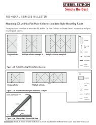
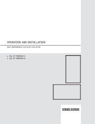
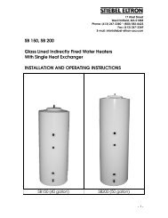
8. SET-UP AND <strong>INSTALLATION</strong>ENGLISH8.1 Set-upNOTICE: THE UNIT SHOULD BE LOCATED IN AN AREA WHEREWATER LEAKAGE FROM THE UNIT OR ANY CONNECTIONS WILL NOTRESULT IN DAMAGE TO THE AREA SURROUNDING THE UNIT.DANGER: THE UNIT MUST NOT BE LOCATED NEAR FLAMMABLE LIQUIDSUCH AS GASOLINE, ADHESIVES, SOLVENTS, PAINT THINNERS, BUTANE,LIQUIFIED PROPANE, ETC. AS THE CONTROLS OF THIS APPLIANCE COULDIGNITE VAPORS CAUSING AN EXPLOSION.Inspect the packaging for damage and remove packaging at theinstallation site. Verify presence of six brass thread to sweat fittings.The installation site must be structurally capable of supporting theweight of the tank when filled. The location has to be above freezing.The water drainage pipe must be freeze proof.8.2 ConnectionRefer to Figure 1 and Figure 2.8.3 Heater InstallationThe installation of the hydronic loop is shown in Figures 4 & 5. Thecircuit must include a Temperature / Pressure Relief Valve, and airvent,a check valve, and an expansion tank.8.4 Hot Water Installation8.4.1 Local Site ConditionsPrior to installation check that the local conditions are compatiblewith the appliance design, especially that the maximum workingexcess pressure of 150 PSI (10 bar.) is not exceeded.8.4.2 Required Pipe Combinations8.4.3 Cold Water Supply Safety ComponentsAll safety components must be installed into the cold water supply(Fill & drail valve, Check valve, isolating ball valve & pressureregulator, see Figures 4 & 5). The order of the individual fittings mustbe in accordance to local regulations.8.4.4 Pressure Regulator SettingsThe pressure regulator has to be set to 150 PSI (10 bar). It canonly be installed into the cold water supply. The supply has to bethoroughly inspected prior to installation. Installation of dirt filtersor any other narrowing of the supply line to the pressure relief valveis forbidden.The temperature & pressure relief valve has to be easily accessible.Expansion water generated during the heating has to flow visibly toa drain. The drainage pipe must be large enough to accommodatewater drainage with a fully opened T & P valve. The drainage pipemust be protected from freezing and must not lead outdoors.The pressure regulator (Figures 4 & 5) has to be set so no waterdrips from the T & P valve.Heavy dripping of the T & P valve can be caused by dirt in the valveseat or water pressure. Water pressure needs to re regulated below150 PSI.8.4.5 Before FillingPrior to filling all screws must be tight.8.4.6 Drainage and Re-circulationDrainage of the hot water tank is via the fill & drain valve (Figures 4& 5).A re-circulator can be attached to a separate socket across thethermometer. Drill the outer casing with a hole saw Ø 50 wheremarked and remove insulation from the socket in that area.For energy conservation, use of a circulator is not recommended.A steel or a copper pipe with insulation can be used for the hotwater connectors. Copper pipe with insulation is especially suitabledue to its low heat loss.Required combinations:Cold water pipelineCopper pipeHot water pipelineCopper pipeSteel pipePlastic pipeSteel or copper pipeSteel or copper pipeWWW.STIEBEL-ELTRON-USA.COM SBB S & SBB PLUS SOLAR STORAGE TANKS | 9