A 2D Finite Volume Non-hydrostatic Atmospheric Model ...
A 2D Finite Volume Non-hydrostatic Atmospheric Model ...
A 2D Finite Volume Non-hydrostatic Atmospheric Model ...

Create successful ePaper yourself
Turn your PDF publications into a flip-book with our unique Google optimized e-Paper software.
A <strong>2D</strong> <strong>Finite</strong> <strong>Volume</strong> <strong>Non</strong>-<strong>hydrostatic</strong> <strong>Atmospheric</strong> <strong>Model</strong> -Implementation of Cut Cells and Further Improvements.Andreas Dobleradvised byDr. Jürg SchmidliProf. Christoph Schär, IAC, ETH ZürichZürich, 02/27/05
Contents1 Introduction.......................................................................................................................................11.1 Background................................................................................................................................11.2 Motivation..................................................................................................................................22 Governing equations and the discrete Archimedes' principle............................................................32.1 The inhomogeneous Euler equations.........................................................................................32.2 The integral form of the inhomogeneous Euler equations.........................................................42.3 <strong>Finite</strong> volume method................................................................................................................42.4 Discrete Archimedes' principle..................................................................................................53 Spatial discretization..........................................................................................................................73.1 Calculation of the numerical flux..............................................................................................73.2 Reconstructing the variables at the cell interfaces.....................................................................83.3 Computing the gradients............................................................................................................93.4 Calculation of the source term...................................................................................................93.5 Reconstruction of the local <strong>hydrostatic</strong> background state.......................................................104 Numerical integration and further developments............................................................................114.1 The 2nd order leapfrog scheme................................................................................................114.2 Divergence damping................................................................................................................134.3 Computational mixing ............................................................................................................144.4 Diffusion..................................................................................................................................154.5 Rayleigh sponge layer..............................................................................................................154.6 Stability....................................................................................................................................155 Boundary conditions and grids........................................................................................................175.1 Uniform Cartesian grid using cut cells....................................................................................185.2 Simplifications.........................................................................................................................205.3 Terrain-following grid.............................................................................................................215.4 Hybrid coordinates...................................................................................................................216 Numerical results.............................................................................................................................236.1 Setup........................................................................................................................................236.2 Performance improvement.......................................................................................................246.3 Linear, non-<strong>hydrostatic</strong> flow....................................................................................................266.3.1 Grid comparison...............................................................................................................266.3.2 Impact of the corrected divergence damping...................................................................286.3.3 Influence of the Rayleigh sponge layer............................................................................286.3.4 The effects of computational mixing...............................................................................306.4 Linear <strong>hydrostatic</strong> flow............................................................................................................306.5 Flow over a Schär hill .............................................................................................................336.6 Thermal bubble........................................................................................................................356.7 Atmosphere at rest...................................................................................................................377 Conclusion and outlook...................................................................................................................397.1 Acknowledgments...................................................................................................................39i
List of figuresFigure 5.1: Illustration of locally reflected cells in a uniform Cartesian grid with cut cells..............19Figure 5.2: Terrain-following grid over a Gaussian hill.....................................................................21Figure 5.3: Hybrid coordinates over a Gaussian hill using uniform coordinates above and terrainfollowingcoordinates below 12000 m..................................................................................21Figure 6.1: Horizontal and vertical velocity perturbations of a linear, non-<strong>hydrostatic</strong> flow. Calculationof background state at every time step. The contour interval is 0.001 m/s. Positive valuesare solid blue and negative values are dash-dotted cyan.................................................25Figure 6.2: As figure 6.1, but background state is calculated every 10th time step...........................25Figure 6.3: Analytic steady state solution of the linear, non-<strong>hydrostatic</strong> flow past a Gaussian hill.The mountain height and half width are 1 m and 1000 m respectively. Horizontal and verticalvelocity perturbations. The contour interval is 0.001 m/s. Positive values are solid blueand negative values are dash-dotted cyan.............................................................................26Figure 6.4: As figure 6.2, but for the terrain-following grid..............................................................27Figure 6.5: Horizontal and vertical velocity of a linear, non-<strong>hydrostatic</strong> flow. The contour interval is0.001 m/s centered around zero for the vertical and around 10 m/s for the horizontal velocity.Bigger values are solid blue and smaller values are dash-dotted cyan. Mixed derivativesin the divergence damping term are neglected......................................................................28Figure 6.6: Horizontal and vertical velocity perturbations for a linear, non-<strong>hydrostatic</strong> flow in thewhole computational domain. No Rayleigh sponge layer at the top. The contour interval is0.001 m/s. Positive values are solid blue and negative values are dash-dotted cyan............29Figure 6.7: As figure 6.6, but with Rayleigh sponge layer at the top.................................................29Figure 6.8: As figure 6.7, but without computational mixing............................................................30Figure 6.9: Horizontal and vertical velocity perturbations for a linear, <strong>hydrostatic</strong> flow past a Gaussianhill. Exact steady state solution (upper panel) compared to simulation results (lowerpanel) after 10000 seconds integration time. The contours intervals are 0.001 m/s for thevertical and 0.004 m/s for the horizontal velocity. Positive values are solid blue and negativevalues are dash-dotted cyan............................................................................................32Figure 6.10: Vertical velocity of a linear, non-<strong>hydrostatic</strong> flow past a Schär hill. Exact solution insteady state (upper panel) compared to simulation after 10000 seconds (lower panel). Thecontour interval is 0.05 m/s centered around zero. Positive values are solid blue and negativevalues are dash-dotted cyan............................................................................................34Figure 6.11: Simulation of a negative buoyant blob of cold air in an otherwise isentropic atmosphere.Potential temperature at 0, 300, 600 and 900 seconds (from top to bottom). Contoursare downwards from 299K with an interval of 1K. Only the right half of the computationaldomain is shown..........................................................................................................36Figure 6.12: Time evolution of maximal vertical velocity above steep topography. Simulation of anatmosphere at rest with unimproved model on terrain-following coordinates......................38Figure 6.13: As figure 6.12, but using all model improvements and hybrid coordinates consisting ofterrain-following coordinates below and uniform above 12000 m. .....................................38iii
List of tablesTable 6.1: Default parameters used for the simulation of a linear, non-<strong>hydrostatic</strong> flow past a Gaussianhill.....................................................................................................................................24Table 6.2: Parameters used for the simulation of a linear, <strong>hydrostatic</strong> flow past a Gaussian hill......31Table 6.3: Parameters used for the simulation of a linear, non-<strong>hydrostatic</strong> flow past a Schär hill....33Table 6.4: List of used parameters for the thermal bubble simulation...............................................35Table 6.5: List of parameters used for the simulation of an atmosphere at rest above steep topography............................................................................................................................................37v
£¤¢¦§©¡¨¥NomenclatureQDamping and filtering coefficientsDeviation of complete atmospheric state from the <strong>hydrostatic</strong> background stateOrder of magnitude of physical vertical accelerationAdiabatic coefficientGravitation potentialArbitrary right hand side functionDensityPotential temperatureeffFghkNphijp 00Local reconstruction of potential temperatureLocal vertical coordinate, aligned with gravity acceleration g vector kInner energyAnalytic horizontal Euler flux functionAnalytic Euler flux function normal to cell boundaryNumerical approximation to the analytic flux function fGravitational accelerationAnalytic vertical Euler flux functionUnit vector aligned with gravitationBrunt-Väisälä frequencyPressure in PascalReference pressureh P ijqh Q ijRLocal <strong>hydrostatic</strong> background pressure functionAnalytic state vector of Euler equationsLocal <strong>hydrostatic</strong> background state vectorGas constant for dry airh R ijsSTvwLocal <strong>hydrostatic</strong> background density functionSource term in Euler equationsApproximation to source termTemperatureHorizontal velocityVertical velocityvi
AbstractOn small scales terrain-following coordinates lead to strongly deformed grids, computational errorsand even numerical instability when following a steep and/or abruptly changing surface. An alternativeapproach is to use height as a vertical coordinate. This then leads to terrain-intersecting coordinatesurfaces and a lower boundary consisting of cut cells. The main aim of the present work is tocompare these two approaches. To this end we implement a cut-cell lower boundary into an existingfinite volume model. Several additional improvements are made to the model. We add a Rayleighsponge layer at the top of the domain, implement computational and physical mixing and correct theimplemented divergence damping. For an accurate calculation of the vertical acceleration the originalwell-balanced finite volume model requires the evaluation of a <strong>hydrostatic</strong> background state atevery time step. It was found that a less frequent update of the <strong>hydrostatic</strong> background state leads toidentical simulation results, but with the benefit of an increase in performance of more than 90%.Several tests were undertaken with the improved model including the simulation of internal gravitywaves triggered by flow past mountains, the nonlinear development of a negative buoyant thermalbubble and an atmosphere at rest over steep topography. The results obtained with the new modelagree well with the reference solutions of these problems.
1.2 MotivationIn [6] Wunderlich implemented a <strong>2D</strong> well balanced finite volume method based on the ideas of Botta etal. in [5]. He used a terrain-following vertical coordinate in his model. In this work we adapt the modelto a cut-cell approach and compare it to the terrain-following approach. To improve performance the <strong>hydrostatic</strong>background state is no longer calculated in every time step. It is rather kept constant for a numberof time steps. Nevertheless the deviation of the complete state from the <strong>hydrostatic</strong> background stateremains small as long as the background state is reconstructed reasonably often. Since the original modelis very sensitive to the choice of the divergence damping coefficients, the divergence damping term isreviewed. Then, the following improvements are made to the model:The implemented divergence damping is corrected (see section 4.2)Computational mixing is added in order to remove small scale noise of computational origin(section 4.3)Physical mixing is added to simulate diffusion (section 4.4)A Rayleigh sponge layer at the top of the domain is introduced in order to absorb upward propa-gating waves (section 4.5)To test the improved model several tests are undertaken. The test cases includeLinear, non-<strong>hydrostatic</strong> flow (see section 6.3)Linear, <strong>hydrostatic</strong> flow (section 6.4)Flow over a Schär hill (section 6.5)Development of a negative buoyant thermal bubble (section 6.6)Atmosphere at rest over steep topography (section 6.7)2
$$%&$$00++$$$$$$2 Governing equations and the discrete Archimedes' principle2.1 The inhomogeneous Euler equationsThe inhomogeneous Euler equations constitute a hyperbolic system of conservation laws where the conservedquantities are the mass, the momenta in every space dimension and the total energy. In two spacedimensions x and z the inhomogeneous Euler equations are given bytu w e & ('*) u u 2 & p x uw + u & ,' & e p .- &wuww 2 pw e p00z g 34 02.1 where is the density, u and w are the horizontal and vertical velocities, p is the pressure, e is the sumof the internal and the kinetic energy, gz is the time independent gravitation potential with g thegravitational acceleration and z the elevation above sea level. The pressure p is related to the flux variables , u , w and e over the thermodynamic equation of statep 5 687.9 , 9 u , 9 w , 9 e: :527.;=< 1:>7.9 e
Cc iR iO'0PPc iPc i/OCc iR ih OO'''00Cc iR iO' dV & O h 2 00PO''I2.4 Discrete Archimedes' principleIn any grid cell c ilet p h i and h ibe exact solutions of the <strong>hydrostatic</strong> relationih Op ih 2.13!3 Owhere p h iis the local pressure and h ithe local density. Integrating (2.13) over grid cell c iand usingGauss' divergence theorem to replace the volume integral of pressure on the right hand side by the surfaceintegral over the cell M boundary c iyields the so called discrete Archimedes' principle of buoyancy1Hc iHCc iih OdVH 3 1D?F p h Hcc in dS .ii2.14 Now assume that we have approximations P iand R ito the exact data pand on cell c i. Then standard finitevolume approximations of the cell averages of the pressure gradient and source term are given byp RQ 1 Hc iHP idV , 2.15!RQ 1Cc iOdV.Hc iH2.16JUsing Gauss' divergence theorem to replace the volume integral in (2.15) by a surface integral yieldsc i.Op SQ 1 Hc iH D(Fc iP in dS2.17 where n is the outward pointing vector normal to the N boundary c i. Now let P hiand R h ibe exact solutionsof (2.13) interpolating P iand R iin the center of cell c i. Using the discrete Archimedes' principle(2.14) the integral in (2.16) can be replaced, with second order accuracy, by1Hc iHdV1Hc iHH 3 1D?F P h Hcc in & dS O h .ii 2 2.18!Thus we have approximated the source term in the finite volume formulation (2.12)1Hc iHCc is q dVc i 2.19!with second order by means of a boundary integral of the local <strong>hydrostatic</strong> pressure function P i h :1Hc iHCc is q dV Q 3 1 Hc iH D?Fc iP i h n dS.2.20 5
wrwHru€rwuwF k s t t I k| ij x S ij s t tw}ƒ}ƒ}3 Spatial discretizationIn this section we show how the right hand side terms of the finite volume formulation (2.12) are spatiallydiscretized. We then have a semi-discrete formulationq i t t su… ti s qt3.1~where g i h qi is the spatially discretized right hand side. To solve this differential equation in time wecan use a standard time integration scheme asuch s the leapfrog scheme or a Runge-Kutta scheme. Detailson time integration are given in section 4.On a two dimensional, logically rectangular grid the finite volume formulation for any grid cell c ijreadsq ijt t st1H D?Fcc ijijf s qt dS x1Hc ijHCc ij s s qt dV.s 3.2tHere f is the outward flux normal to the cell boundary defined in (2.9). Using midpoint approximationfor the integrals over the boundary interfaces then yieldsu*vq ijt t st14 {H H#yc ij 1 kz3.3„u vwhere jF kis the numerical outward flux normal to the k-th (east, north, west and south) interface, I kisthe area of the k-th interface and S ijis the approximated source term inside cell c ij. We now have to calculatethe numerical flux function at the interfaces and the source term.3.1 Calculation of the numerical fluxTo approximate l the flux kf over the cell interfaces we need a nnumerical flux function F qm kat these interfacesand the interface areas I k. For the eastern interface of cell c ijat time step t the numerical fluxmust fulfill1s F tS iq , jtzz f qC iq , j s t t.t dz. si , j‚z i , jw3.4~Here the o indexes i p , j denote the bottom and top of the eastern interface respectively. The integralsare approximated by the analytic fluxes at the interface midpoints. This yields the numerical flux functionF iq s , jt n *s f Q iq , s jt n t.tt3.5~*where Q iq , jis an approximation to the state vector at the eastern interface midpoint of cell c ij. Introducinga new index at the top of the reconstructed state vector Q at the interfaces, denoting the direction ofreconstruction, the average state can be written as*Q iq , j1Q east2 ijQ west iq 1 jt . x s3.6„7
€€€uuG tQ ijt s 0tuww€wwt s Q ij s x ij,t 0xv€t tv€€}ƒ}}*In other words Q iq , jis calculated by averaging the reconstructions from the center of cell c ijto the eastand from the center of cell c i† 1 jto the west. Averaging the state at the interfaces assures the uniquenessof the values used for the numerical fluxes.The numerical flux at the northern, western and southern interface is computed analogously. But sincetwo cells lying next to each other share an interface we calculate only the numerical flux at the westernand southern interfaces. The numerical flux at the eastern and northern interfaces is then calculated withF iF i , j, jt t st t su vF i 1Ž , j s t t ,F i , j 1Ž s t t .3.7„3.8~With the notation h i‡ , j and h i , j‡ for the western and southern interface area of cell c ijthe sum of the fluxeson the right hand side of (3.3) can be calculated asu*v{’‘ 4F kt ” I k| ij • – h “ i 1Ž j— ,k 1‘F i 1Ž , j “ t ” – h i , j 1Ž˜—‘F i , j 1Ž“ t ”Sš h iŽ , j—‘F iŽ , j “ t ”Sš h i , jŽ˜—‘F i , jŽ›“ t ” .3.9~3.2 Reconstructing the variables at the cell interfacesTo evaluate the numerical flux function we need to reconstruct the complete state vector at the cell interfacemidpoints. In this reconstruction well balanced and standard methods differ. Well balancedmethods use the local <strong>hydrostatic</strong> background state to interpolate the complete state vector at the interfaceswhere standard methods usually simply interpolate the data between two neighboring cells. Theevaluation of the local <strong>hydrostatic</strong> background state is explained in section 3.5We now show how the complete state is reconstructed at the interface midpoints in our well balancedmodel. Basically we use a linear Taylor approximation. As we do not necessarily evaluate the local <strong>hydrostatic</strong>background state at every time step a time derivative appears in addition to the spatial gradientterm. Eventually the local approximation Q ij to the complete state vector at the interface midpoints atˆ time t after the last evaluation of the background state readsQ ij s x iœ , j ,t 0xQ ij s x i , jœ ,t 0xt tt thQ ,t ij sR‹ iœ 0tSx s , jx iœ , j vhQ ij s‹ i , jœ ,t 0x tSx s i , jœx i jt/ G i Š Q ij s t 0tSxx i jt/ G j Š Q ij s t 0tSxt G tQ ij s t 0t ,t G tQ ij s t 0t .3.10~hHere t 0is the time the local <strong>hydrostatic</strong> background state Q ij was evaluated last and G i ‰ Q ijand G j Š Q ijare the two dimensional approximations to the gradients of the deviation of the complete state from thelocal <strong>hydrostatic</strong> background state along the computational dimensions i and j respectively. For a moredetailed derivation of the spatial gradients see Wunderlich in [6]. How the gradients are calculated isshown in section 3.3. The time derivative vector in (3.10) and (3.11) is given bys 3.11t1Q ij s x ij,t 0t.t .s 3.12thNote that Q ij s‹ ,t 0t#Œ t xhQ ij s‹ ,t 0where t t 0is the last time the local <strong>hydrostatic</strong> background state wasˆcalculated and t is the time that has passed since then.8
®¬¬1, juS iju v1, jv1, jt}}}3.3 Computing the gradientsThe evaluation of the complete state at the cell interfaces in (3.10) and (3.11) requires an approximationto the gradients of the deviation from the local <strong>hydrostatic</strong> background state along the computational dimensionsi and j. We calculate the deviations in the center of all neighbor cells of cell c ij. For the easterncell this deviation isŠ Q iQ ihQ ij s‹ iwhere ‹ i 1, j is the value of the local vertical coordinate ž evaluated at the center of cell c i 1, j. For theother three cells the deviation is calculated analogously. From this four deviations we can compute fourgradients, two along each computational dimension. How this is done in detail for curvilinear grids takingmetric terms into account is shown in [6]. To avoid spurious oscillations the two gradients along thesame computational direction are smoothed using a gradient limiter function. To smoothen the gradientsg 1and g 2we have used either the minmod limiter3.13~“ g 1,g 2” : •12 “ sign “ g 1”Sš sign “ g 2”.” — min “. g 1 , g 2 ” ,3.14~the monotonized central limiter1s g 1,©g©2: t u 2 sign g sign s 1g tSx s 2min 2 min © © © g 1g x 2t.t/ s ¯ g 1, g 2, t © 2 °ss 3.15tor the Van Leer (sometimes also called WENO (weighted essentially non oscillatory)) limiterw “ g 2” — g 1š w “ g 1” — g 2“ g 1,g 2: ” • w g “ 1w ”Sš g “ 2”3.16~where w is the regulated absolute value w Ÿ g i S¡2¢ Ÿ g i2 £ ¤, and ¥’¦ 10§6 .3.4 Calculation of the source termAs seen in section 2.4 the source term inside cell c ijcan be approximated with second order by1P h c ijn dS.ij©c ij©Sª(«s 3.17tTo perform a discrete integration of the source term in each cell the <strong>hydrostatic</strong> background pressure hasto be defined at the interfaces. In section 3.5 the <strong>hydrostatic</strong> background state is defined for each cell asa function of the local vertical coordinate ¨ . The discrete integration of the vertical momentum componentof the source term then reads±wS ij t s t² ² 1c ij4 ³k 1hP ij sR‹ k t/zh k n . ´k iju vAll three other components of the source term of the inhomogeneous Euler equations (2.1) equal zero.s 3.18t9
¼¼µ½¼u¼½u}}}3.5 Reconstruction of the local <strong>hydrostatic</strong> background stateWe need the local <strong>hydrostatic</strong> background state at the cell interfaces to approximate the source term insideeach cell c ijand to reconstruct the complete state at the interface midpoints. We therefore define thelocal <strong>hydrostatic</strong> background state for each cell as a function of a local vertical coordinate ¨ . The local<strong>hydrostatic</strong> background state has to fulfill the following three requirements in each cell c ijof the computationaldomain:1. fulfill the <strong>hydrostatic</strong> relationhP ij” “R½hg R • – ij “R½ ” ,3.19~2. interpolate the averaged data in the cell midpoint:hQ ij0t sQ ij,3. fulfill the thermodynamic equation of state for ideal gases3.20~hijt s‹hP ijt s‹hR R ijt· s‹p 00hP ijt¹¸»º s‹3.21~where p 00 is the reference pressure defined at sea level and R is the gas constant of dry air. Using (3.21)hto replace the expression for R ij sR‹ in (3.19) yields the ordinary differential t equationhP ij” “R½– g P hij” “R½¾• hR ”·ij “R½p 00hP ij”¹¸»º “R½s 3.22thfor the pressure P ij s‹ of the local <strong>hydrostatic</strong> background state. Together with a given potential temperatureprofile and the interpolation condition (3.20) the ODE (3.22) can be solved. How this is done intdetail for different temperature profiles is shown by Müller in [7]. With the solution of equation (3.22)we can reconstruct the complete local <strong>hydrostatic</strong> background state as a ‹ function of in each cell analyticallyassuming that the horizontal and vertical velocities are constant in each cell.10
ÌÌÐQ nØ Q nÙ2Ú assÛÝÜ Q nÓ 1Þ 2Q nÙ Q nÔ 1ß . à 4.3áÐ4 Numerical integration and further developmentsIn section 3 we spatially discretized the right hand side terms of the finite volume formulation (2.12).We now want to solve the resulting differential equationq i t Î Íti Í qÎ Ñ 4.1ÒÏÐwhere ¿ i À qÁ is the spatial discretization of the right hand side terms.4.1 The 2 nd order leapfrog schemeA very common and efficient scheme for time integration is the 2 nd order leapfrog scheme. For somegiven numerical approximations Q n and Q 1 to the à analytic states q x ,t à and q x ,t the scheme tocalculate the numerical approximation Q n 1 at time t t nÄ t nÅ is1Ä nÉ*Ê 1È nÇ nÆBecause the 2Ñ 4.2ÒQ 1 Q 2 nd order leapfrog scheme is a three-level scheme we need theÖ × Í t Q n 1Õ Î .nÓ nÔ Ïstates Q 0 and Q 1 to initiate thetime integration. Q 0 is given by the initial state of the atmosphere and Q 1 is calculated using a standardtwo-level scheme. In addition to the leapfrog scheme Wunderlich [6] also implemented a 3 rd orderRunge-Kutta scheme which we use to calculate Q 1 .The main problem when using the leapfrog scheme is the appearance of computational modes whichcan lead to numerical instabilities. To prevent these modes from growing we use an Asselin filter wherethe filtered value Q n is given byThe damping coefficient Ë ass is a real, positive number typically chosen between 0.05 and 0.2 for atmosphericmodeling. Taking the Asselin filter into account the leapfrog scheme becomesà 4.4áQ nÓ 1 ÏQ nÔ 1Õ 2 Ö t ×Í Q n Î .11
ÍãååÌÌ ÍãÍãååçããÍnÓ 1 çèÞååÎ t éÍÌãÙÌ ÍnÓ 1 çãÎ. à 4.8áIn [5] the authors suggested to rewrite the inhomogeneous Euler equations using the homogeneous statevectorq Ï2âEããuwä eà 4.5áinstead of the inhomogeneous state vector defined in (2.3). The state vector we use in our model is asdefined here in (4.5). Although this is just an implementation detail we consider here the effects of thischange for the sake of completeness. The change yields an additional term on the right hand side of theinhomogeneous Euler equations which then areq Ø Þtfxhzs Ù rwhereà 4.6ár Ï æ000à 4.7áis the additional term added to the right hand side. Using the homogeneous state vector (4.5) the ã(èenergyequation of (4.1) becomestÍ qÎ çteÎã,èIn the used leapfrog scheme the energy equation therefore has to be updated after each time step byadding the r term to the right hand sideÏÐnÓ 1 ênÔ 1 Î . Í 4.9ÎeÎeÎ12
ìëu ,î dî wï Ïìëu ,î dî wÏ2óìëìëìëìëx ðz ðz ðx ôz ôÌÌÌÌÌÌ0 øhuÎhuÎÕÕÕÕÕÕÌÌÌÌÌÌw Îh wÎx z ñÌhwÎ4.2 Divergence dampingIn [6] Wunderlich showed how to implement a divergence filter. By adding a numerical diffusion termd Ï ÷0udîwdîà 4.10áto the right hand side of the semi discrete equation (4.1) acoustic waves can be damped. Surprisingly hismodel is very sensitive to the values chosen for the divergence filter coefficients. It was found that thedamping term had not been implemented correctly. There had been an error in the implementation of themixed second derivatives. This led to incorrect results and to the observed sensitivities. Replacing theold momentum damping termx ðÌ 2Íãx 22 ÌÍx z ñÌãuÎuÎÑ 4.11ÒÌ 2ÍãÌ 2Íãx Ì zz 2wÎwÎñ.òwith the correct termx 2Ì 2Íãx Ì z õuÎÌ 2Íã2 ÌuÎ Íz xÌãz 2à 4.12áwÎÌ 2Íãõömakes the model less sensitive to the choice of the divergence filter ëìcoefficientsx and ë ìTo take the local <strong>hydrostatic</strong> background state into account we implemented a new damping method.The new damping term replaces the old momentum damping term withz .Ì 2Íãhdîu ,îwÌ 2Íãx 2à 4.13á2 ÌÍz xÌãz 2Ï ïÌ 2Íãñ#òwhere í hdenotes the density of the local <strong>hydrostatic</strong> background state. The default term we use is (4.13)but the old, corrected damping term (4.12) is also available as an option of the leapfrog scheme.13
ðåùÏÕìãããìëxÏìÞÏãÖããzÏìããTo calculate the damping term in each cell c ijthe derivatives with respect to x are approximated using finitedifferences:x 2å 2 ù h uñijúh ß Þij ÜRû iÓ 1, jÛüÜ ju iÓ 1,x ijxßSÙ2ù iÔ 1, j1x2 iÓ 1, j Üh ß Þij ÜRû iÔ 1, jÛÝÜ ju iÔ 1,x iÓ 1, jxß iÔ 1, jxÞ iÓ 1, j Üx ijßÜ x ijÞx ijßSÞ ùxß iÔ 1, jhij Ü 0 uÞ ß ijÛÝÜ x iÓ 1, jxß iÔ 1, j.à 4.14áThe derivatives with respect to z are computed analogously. The mixed second derivatives are approximatedusing centered differences first in x direction and then in z direction or vice versa. In the discretecase the ëdamping coefficients and ìx zare ëxtÖ x 2ëìandzz 2Öt Öà 4.15áwhere ì x and ì zare non-dimensional coefficients. To ensure stability the divergence damping is appliedto the old values of the state vector q. According to the ARPS User Guide [9] the coefficients ýxand ýzhave to be smaller than 0.75 to assure stability.4.3 Computational mixingWe introduce numerical smoothing in the computational space in order to remove small scale noise ofcomputational origin following the ARPS User Guide [9] . Therefore second order computational mixingterms Cþu ,þw are added to the right hand side of the conservation equations of momentum. Like divergencedamping the mixing is applied to the previous time level to ensure stability. The mixing is appliedto the perturbations u' and w' form the local <strong>hydrostatic</strong> background state. The mixing terms usinga second order finite difference operator along the computational variables ÿ and in each cell c ijare:CK x ÍK z Íh hij iÔ Í¢ 1,' iÔ 1, j2ijç Õ Í£¢ jÎ ijÎ ' ijh ' hÍ£¢ i , jÔ jÔ 1 i , 12Õç Í¢ ijÎ ' ij Îijijhij Í£¢ jÎ iÓ 1,' jÎ iÓ 1,h ' Í£¢ i , jÓ 1 i jÓ , 1 Î ÎijÍ 4.16Ρh hwhere is either u or w. Note thatij Í£¢ ij0Îij Í since is the local vertical coordinate. ÎThe parametersK xand K zequal t ¤ z¥§¦ and t respectively. Subject to [9] the non dimensional ¤ coefficientsx¤ x¥§¦andzmust be smaller then 1/8 to guarantee stability. If not stated otherwise we use a value of ¨ 0.0005for both coefficients in order to keep the computational mixing small.14
+#t ,)+min i , j 0z j1q q 0" à 4.18á224.4 DiffusionAn additional diffusion termîØ2ù,î diffu wKu xxÙw xxÙu zzw zzà 4.17áis added to the right hand side of the momentum equations to simulate diffusion. The second derivativeswith respect to x and z are approximated using finite differences analogously to (4.14). K is the diffusioncoefficient.4.5 Rayleigh sponge layerAlso according to the ARPS User Guide [9] a damping layer is introduced at the top boundary in orderto absorb upward propagating wave disturbances and to eliminate wave reflection at the top boundary.For this purpose a Rayleigh damping termR D R sin² 2z z Dz T z D !is added to the right hand side of the conservation equations. The Rayleigh damping term operates onthe perturbation of the state vector q from the undisturbed initial state q 0 . It is applied after updating theenergy equation in the leapfrog scheme. z Dis the height of the bottom of the damping layer and z Tis theheight of the top boundary. Typically the thickness of the layer corresponds to about 1.5 vertical wavelengths.The inverse ý damping coefficient 1 Rhas a magnitude of 10 to 50 time steps.4.6 StabilityIn two dimensions the CFL criterion for stability including diagonally propagating waves ispmax p i , $ jmin i , j x i , z"j% %t#('*)224.19 "&%pwhere x i and z j are the horizontal and vertical, nonuniform grid spacings and max p i , j is the speedof the fastest propagating wave in x- or z-direction. However, in our atmospheric simulations the wavespeeds are dominated by the sound speedc :4 5 R T4.203 where is the adiabatic coefficient, R is the gas constant for dry air and T is the temperature in Kelvin.pThus we use c as an approximation to max p i , j . The size of the time step is therefore limited by22 -/.x i , +c ..4.213With a grid spacing of 300 m a value of 0.4 seconds is an appropriate choice for the time step. To preventthe simulations from running into instability we implemented a CFL break condition that stops thesimulation as soon as the CFL number gets too big.15
6
m ,J p " p 29p m " ?2?5.1 Uniform Cartesian grid using cut cellsTo avoid errors coming from metric terms we replace the terrain-following grid with a uniform Cartesiangrid. Using such a uniform Cartesian grid requires a special treatment of the boundary cells that arecut by the topography. In [10] Forrer described a new way to treat these cut cells. To avoid numericalinstabilities due to small cell sizes he suggested to treat the cut cells as whole cells instead of using onlythe part of the cut cells lying in the physical domain. A boundary treatment was developed that locallyreflects the velocity fields at a straight boundary line. The prognostic equations in the cut cells are thensolved as if there was no boundary. All cell values lying outside the physical domain required to updatethe state variables in the cut cells are locally reflected from the inside of the physical domain. At last theboundary conditions (5.2) for density and energy density are applied.We now show how the local reflection is done. Inside the cut cells the topography is approximated by astraight line that serves as symmetry line. Suppose this symmetry line goes through the point m and thevector normal to the line pointing into the physical domain is given byG sinGIH cosnCED£F5.63Toutside the physical domain can now be re-A where is the lead angle of the line. Any pB pointflected at the symmetry line to the pointx , z@n " n5.7@lying inside the physical domain.18
q ijCRJ Zq i , jP 1 Sq p " RJ""q r m ,J p "9"""?222Then the state vector q can be extrapolated to the point p withwhere RK is the reflection matrix5.83 1 0 0 00 cos 2 sin 2 00 sin 2 0.5.93 1[cos 20 0 0Using (5.9) we can now define the state vector inside any cut cell c ijas1Qc ijQ£RTS1 q 0 x , z1 dx dz U Sc ijr ijV2W RJ qc 0 x , z1 dx dzX .ijij-5.10@Here c 1 ijis the part of the cut cell lying inside the physical domain and2Mr ij c L ijcut cell originally lying outside the physical domain, see figure 5.1.is the reflected part of theFigure 5.1: Illustration of locally reflected cells in a uniform Cartesian grid with cut cellsIn order to update the state vector in the cell c ij we need the complete actual state vectors in the regularcells c i , jN 1 ,c i , jN 2 , in the cut cells c iO 2, j ,c iO 1, j ,c iN 1, j ,c iN 2, j and in the empty cells c i , jO 1 ,c i , jO 2. Note thesimpler stencil in comparison to the terrain-following grid. The state vector in the regular cells is givenby (2.11) and in the cut cells it is defined by equation (5.10). To calculate the state vector in the emptycells we again use the assumption of local reflection of the velocity field. For the cell c i , jP 1 this yieldsr ijVc i , jYW RJ1ijq x , z " dx dz.5.11319
iƒi…Š…‹‹To evaluate the integral in (5.11) numerically we make a bilinear interpolation of the function q \ x , z ] atthe reflected cell center r mi , j^ 1 ,_ ij ` C i , jO 1a between the centers of the surrounding regular or cut cells, cf.figure 5.1. The coordinates of the reflected cell center can be calculated withr mi , jY 1 ,J ij c C i , jP 1dfe C i , jP 1g 2 c9c C i , jP 1g m ijdh n ijd£h n ij.5.12ŒAfter reflecting the velocity field we apply the boundary condition (5.2) for density and energy densityto ensure that we have a vanishing normal derivative.So far we have only implemented the case where any empty cell is used to update exactly one cut cell.In this case we can update the cut cells and the empty cells after each time step when we apply theboundary conditions. The case where an empty cell is used by two different cut cells is more complicatedto solve and hasn't been implemented in this work. A solution would be to calculate the state vectorson the fly when they are needed to update the cut cells instead of calculating them before the actual updating.5.2 SimplificationsDue to the use of a uniform Cartesian grid our model can be simplified in some aspects. There is no verticalflux over the eastern and western and no horizontal flux over the northern and southern cell boundariesanymore. This simplifies the numerical flux over a cell boundary in (3.3) tokml 4F kt o I kp ij qr n*z n f Q i= , n jo9ofs n t*f Q iP , n joto9ous*r t n x n h Q n i , j=‹n t o9ofs h n Q i , jP5.13Œkj 1The normal vector on the eastern and western interface doesn't have any z-component anymore and thediscrete integration of the vertical momentum component (3.18) becomes4v zw 1 x S xhzij t n o}p qw c ij h n£{ ko£| k n | k ijz 1 x~hp qwrxij 1c ij ohw i n{ , p j ij j€ o 5.14Ži , n£{ .ky ijAs the grid is now uniform the second derivatives with respect to x in (4.14) read‚„ƒ2 h h h h …i€ jd jd 0d g ui ijx 2c£ˆ 1,u i 1, j2 … ij c u ij‰ ij cˆ 1,u i€ 1, jx 2 5.15Œ†ij‡and analogously for the z direction. Furthermore the local vertical coordinate b doesn't vary along thenow horizontal i-coordinate anymore. This causes some additional simplifications in the calculation ofthe computational mixing and divergence damping terms as the local <strong>hydrostatic</strong> background density isnow constant along the i-coordinate.*n t o9o9o .20
5.3 Terrain-following gridThe terrain-following grid we use in this work is given by Wunderlich in [6]. The coordinate surfacefollows the topography at the bottom and slowly level off to the top as in figure 5.2.Figure 5.2: Terrain-following grid over a Gaussian hill5.4 Hybrid coordinatesInstead of using terrain-following coordinates in the whole physical domain we have also the opportunityto use uniform coordinates in the upper part of the domain. This yields hybrid coordinates as in figure5.3 where we use uniform coordinates above 12000 m and terrain-following below.Figure 5.3: Hybrid coordinates over a Gaussian hill using uniform coordinatesabove and terrain-following coordinates below 12000 m21
h c x dfe1‰ c x— adh c x dfe H exp – g c x— a dž‹6 Numerical resultsAll tests are performed in two dimensions. The initial atmospheric state is either isentropic or constantlystratified (constant Brunt-Väisälä frequency). To simulate the behavior of a thermal bubble (see section6.6) we have the possibility to insert an elliptic thermal perturbation into the initial state. More detailson the typical potential temperature, density and pressure profiles of the two types of atmosphere aregiven in [6].The steady state solutions produced by the flow of a stratified fluid over a mountain depends on the differentheight and width of the mountain. We distinguish between linear and nonlinear as well as <strong>hydrostatic</strong>and non-<strong>hydrostatic</strong> flows. To classify the flows we use the non-dimensional mountain widthand height6.1Œ‘h e h N u 0.6.2ŽHere a is the mountain half width, h is the height of the mountain and u 0is the initial horizontal velocity.Hydrostatic flows are flows where the time a parcel of air needs to cross the mountain is much biggerthan the inverse Brunt-Väisälä frequency 1/N. With use of (6.1) a <strong>hydrostatic</strong> flow is therefore characterizedby a 1. Linear flows are characterized by a low non-dimensional mountain height ‘h ’ 1 typicallyaround 0.001. To test our model we simulate <strong>hydrostatic</strong> and non-<strong>hydrostatic</strong>, linear flows.6.1 SetupThree hill types with a maximum height H and a half width a are defined by the topography functionh “ x” . They arethe Gaussian hilla q a N u 0‹h x c dfe H exp a – g c x—2˜d ,6.3Žthe Bell hillH26.4Œand the Schär hillx š› œ cos .22˜6.5ŽThe parameter • in (6.5) defines the wavelength of the Schär hill. We simulate the flow over a Gaussianhill as well as the flow over a Schär hill.23
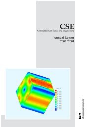
6.2 Performance improvementThe main part of increase in performance is due to the change in evaluating the local <strong>hydrostatic</strong> backgroundstate. Instead of doing the time consuming evaluation every time step we merely do it every 10 thtime step. To illustrate the resulting increase in performance we consider a typical simulation of a linear,non-<strong>hydrostatic</strong> flow past a small Gaussian hill. The simulation is done using the cut-cell approach. Thecomplete list of used parameters is given in table 6.1. For this simulation the number of calls for theprocedure to calculate the local <strong>hydrostatic</strong> background state has been reduced from 12501 to 1251calls. This reduces the totally used CPU time from about 6500 seconds to about 3400 seconds which isan increase in performance of more than 90%. However, not calling the procedure every time step doesnot have a noticeable impact on the solution. Figure 6.1 shows the result of a simulation where the local<strong>hydrostatic</strong> background state is evaluated every time step, figure 6.2 the same for every 10 th time step.time integration schemeatmospheremountain heightmountain half widthmountain typehorizontal domain sizevertical domain sizehorizontal cell sizevertical cell size rangenumber of horizontal grid cellsnumber of vertical grid cellsinitial Brunt-Väisälä frequencybottom potential temperatureinitial vertical velocitytime stepintegration timeparameter value unitx-divergence damping coefficientz-divergence damping coefficientAsselin coefficientRayleigh damping coefficientRayleigh damping layer thicknessx-computational mixing coefficientz-computational mixing coefficientleapfrogstratified11000Gaussian4021400300100700.01288100.450000.050.050.050.0290000.00050.0005Table 6.1: Default parameters used for the simulation of a linear, non-<strong>hydrostatic</strong> flow past a Gaussian hill.--mm-kmkmmm--1/sKm/sss----m--24
elative horizontal velocity u [m/s]relative vertical velocity w [m/s]1000010000900090008000800070007000height [m]60005000height [m]60005000400040003000300020002000100010000−1 −0.5 0 0.5 1widht [m]x 10 40−1 −0.5 0 0.5 1widht [m]x 10 4Figure 6.1: Horizontal and vertical velocity perturbations of a linear, non-<strong>hydrostatic</strong> flow. Calculationof background state at every time step. The contour interval is 0.001 m/s. Positive valuesare solid blue and negative values are dash-dotted cyan.relative horizontal velocity u [m/s]relative vertical velocity w [m/s]1000010000900090008000800070007000height [m]60005000height [m]60005000400040003000300020002000100010000−1 −0.5 0 0.5 1widht [m]x 10 40−1 −0.5 0 0.5 1widht [m]x 10 4Figure 6.2: As figure 6.1, but background state is calculated every 10 th time step.25
6.3 Linear, non-<strong>hydrostatic</strong> flowWith the default parameters from table 6.1 we get a non-dimensional mountain width Ÿa 1 and a non-dimensionalmountain height ¡h ¢ 0.001. Thus, we have a linear and non-<strong>hydrostatic</strong> flow. Figure 6.3 givesthe analytic steady state solution in a domain of 20 km in the horizontal and 10500 m in the vertical. Wecan see a stationary wave with a downwind tilt typical for <strong>hydrostatic</strong> flows. Comparing the analytic solutionto the simulation results shown in figure 6.1 and 6.2 we see, that our model is able to simulate thetypical wave pattern in an appropriate way. The simulation results are very smooth and especially in thelower region the amplitude is close to the analytic solution. In the next subsections we want to showhow the different improvements made during the course of the present work affect the results and wewill compare the new cut-cell approach to the old terrain-following grid.relative horizontal velocity u [m/s]relative vertical velocity w [m/s]1000010000900090008000800070007000height [m]60005000height [m]60005000400040003000300020002000100010000−1 −0.5 0 0.5 1widht [m]x 10 40−1 −0.5 0 0.5 1widht [m]x 10 4Figure 6.3: Analytic steady state solution of the linear, non-<strong>hydrostatic</strong> flow past a Gaussian hill.The mountain height and half width are 1 m and 1000 m respectively. Horizontal and vertical velocityperturbations. The contour interval is 0.001 m/s. Positive values are solid blue and negativevalues are dash-dotted cyan.6.3.1 Grid comparisonThe assumptions we made in the cut-cell approach in section 5.1 are feasible for simple linear test cases.Thus, we can use it for all simulations we consider here with exception of the <strong>hydrostatic</strong> balance 6.7where we use the terrain-following grid. The simulation of the flow past a Schär hill, shown in section6.5, is also done using the cut-cell approach. To prove that our cut-cell approach works we show herethe results of a simulation using the same parameters as in table 6.1 but on a terrain-following grid. Wedecrease the time step from 0.4 to 0.35 seconds to get good, smooth results. When we compare figure6.4 to figure 6.1 or 6.2 there is almost no visible difference. But where the 5000 seconds of integrationtime on the terrain-following grid uses 3900 seconds of total CPU time, the cut-cell approach only needs3400 seconds. This improvement in performance results from some of the simplifications of the cut-cellapproach mentioned in section 5.2 and of course from the bigger time step. Using a initial bottom potentialtemperature of 255 K instead of 288 K decreases the fastest propagating wave speed and allows us26
to run the simulation on a terrain-following grid with a time step of 0.4 seconds. The totally used CPUtime then reduces to about 3700 seconds which is still 300 seconds more than required for the cut-cellapproach.relative horizontal velocity u [m/s]relative vertical velocity w [m/s]1000010000900090008000800070007000height [m]60005000height [m]60005000400040003000300020002000100010000−1 −0.5 0 0.5 1widht [m]x 10 40−1 −0.5 0 0.5 1widht [m]x 10 4Figure 6.4: As figure 6.2, but for the terrain-following grid.27
6.3.2 Impact of the corrected divergence dampingTo show how the corrected derivatives in the divergence filter decrease the sensitivity to the choice ofthe damping parameters we consider a simulation without taking mixed second derivatives into account.The parameters £x e 0.001 and £ ze 0.0044 used by Wunderlich in [6] are increased to the default values£x e £ ze 0.05. Therefore, we expect the wind pattern to get smoother. But as can be seen in Figure 6.5this increase almost cancels out the wave pattern when not using the mixed derivatives. This is also inagreement with the statements of Wunderlich in [6]. Nevertheless the remaining wave pattern is nowvery smooth.horizontal velocity u [m/s]vertical velocity w [m/s]1000010000900090008000800070007000height [m]60005000height [m]60005000400040003000300020002000100010000−1 −0.5 0 0.5 1widht [m]x 10 40−1 −0.5 0 0.5 1widht [m]x 10 4Figure 6.5: Horizontal and vertical velocity of a linear, non-<strong>hydrostatic</strong> flow. The contour intervalis 0.001 m/s centered around zero for the vertical and around 10 m/s for the horizontal velocity.Bigger values are solid blue and smaller values are dash-dotted cyan. Mixed derivatives in the divergencedamping term are neglected.However, when we do not neglect the mixed derivatives, as we usually don't, we get results that are ingood agreement with the analytic solution as for example in figure 6.2.6.3.3 Influence of the Rayleigh sponge layerThe Rayleigh sponge layer at the top is introduced to eliminate wave reflections at the boundary and toabsorb upward propagating wave disturbances. To illustrate its effects we made a simulation with thedefault parameters given in table 6.1 but turned off the sponge layer. The results are shown in figure 6.6.Without sponge layer some waves are reflected at the top. They start to propagate downwards and todisturb the solution. Whereas with the sponge layer the waves are filtered out as can be seen in figure6.7.28
x 10 4 relative horizontal velocity u [m/s]x 10 4 relative vertical velocity w [m/s]221.81.81.61.61.41.4height [m]1.210.8height [m]1.210.80.60.60.40.40.20.20−2 −1 0 1 2widht [m]x 10 40−2 −1 0 1 2widht [m]x 10 4Figure 6.6: Horizontal and vertical velocity perturbations for a linear, non-<strong>hydrostatic</strong> flow in thewhole computational domain. No Rayleigh sponge layer at the top. The contour interval is 0.001m/s. Positive values are solid blue and negative values are dash-dotted cyan.x 10 4 relative horizontal velocity u [m/s]x 10 4 relative vertical velocity w [m/s]221.81.81.61.61.41.4height [m]1.210.8height [m]1.210.80.60.60.40.40.20.20−2 −1 0 1 2widht [m]x 10 40−2 −1 0 1 2widht [m]x 10 4Figure 6.7: As figure 6.6, but with Rayleigh sponge layer at the top.29
6.3.4 The effects of computational mixingComputational mixing removes small scale noise of computational origin. Figure 6.8 shows the result ofanother simulation using the default parameters but this time without computational mixing. When wecompare the results to those shown in figure 6.7 above we see, that the computational mixing preventssmall scale disturbances from growing. For example the vertical velocity disturbances on the left side ofthe domain are an effect of the periodic lateral boundary conditions. They are visibly smaller when usingcomputational mixing. Also the solution at the lower boundary is somewhat smoother. The maindrawback of computational mixing is that it also prevents correct wave patterns from growing. Thereforethe amplitude of the mountain waves are slightly closer to the analytic solution when we do not usecomputational mixing.x 10 4 relative horizontal velocity u [m/s]x 10 4 relative vertical velocity w [m/s]221.81.81.61.61.41.4height [m]1.210.8height [m]1.210.80.60.60.40.40.20.20−2 −1 0 1 2widht [m]x 10 40−2 −1 0 1 2widht [m]x 10 4Figure 6.8: As figure 6.7, but without computational mixing.6.4 Linear <strong>hydrostatic</strong> flowOur second test case is the simulation of a linear, <strong>hydrostatic</strong> flow past a Gaussian hill. The Mountainheight H is again 1 m but the mountain half width a is now increased to 5000 m. This yields the non dimensionalmountain height and width ¤h ¥ 0.001 and ‘a e 5 which characterize a linear and <strong>hydrostatic</strong>flow. We use again the cut-cell approach. The complete list of used parameters is given in table 6.2.Figure 6.9 shows the analytic solution in the steady state compared to the simulation results after 10000seconds. Again, the simulation results are close to the analytic solution.30
parameter value unittime integration schemeatmosphereleapfrogstratified--mountain heightmountain half widthmountain type15000Gaussianmm-horizontal domain sizevertical domain sizehorizontal cell sizevertical cell size rangenumber of horizontal grid cellsnumber of vertical grid cells502150030010070kmkmmm--initial Brunt-Väisälä frequencybottom potential temperatureinitial vertical velocity0.01288101/sKm/stime stepintegration timex-divergence damping coefficientz-divergence damping coefficientAsselin coefficientRayleigh damping coefficientRayleigh damping layer thicknessx-computational mixing coefficientz-computational mixing coefficient0.4100000.050.050.050.0290000.000050.00005ss----m--Table 6.2: Parameters used for the simulation of a linear, <strong>hydrostatic</strong> flow past a Gaussian hill.31
elative horizontal velocity u [m/s]relative vertical velocity w [m/s]1000010000900090008000800070007000height [m]60005000height [m]60005000400040003000300020002000100010000−2 −1 0 1 2widht [m]x 10 40−2 −1 0 1 2widht [m]x 10 4relative horizontal velocity u [m/s]relative vertical velocity w [m/s]1000010000900090008000800070007000height [m]60005000height [m]60005000400040003000300020002000100010000−2 −1 0 1 2widht [m]x 10 40−2 −1 0 1 2widht [m]x 10 4Figure 6.9: Horizontal and vertical velocity perturbations for a linear, <strong>hydrostatic</strong> flow past aGaussian hill. Exact steady state solution (upper panel) compared to simulation results (lowerpanel) after 10000 seconds integration time. The contours intervals are 0.001 m/s for the verticaland 0.004 m/s for the horizontal velocity. Positive values are solid blue and negative values aredash-dotted cyan.32
h c x dfe H exp – g c x— a dcos 2 x š›©œ‹6.5 Flow over a Schär hillA third test case is the flow over an idealized topography, the so called “Schär-Hill”. The topography isgiven by2˜6.6Œwith ¦¨§ 4 km, H e 250 m and a e 5 km. All other parameters we use are listed in table 6.3. Figure 6.10shows the comparison of our simulation after 10000 seconds integration time, again computed using thecut-cell approach, with the analytic steady state solution. The results we get are comparable to those givenin literature using approximatively the same grid spacing and a well balanced method, e.g. Botta etal. in [5].parameter value unittime integration schemeatmosphereleapfrogstratified--mountain heightmountain half widthmountain typemountain wavelength2505000Schär4000mm-mhorizontal domain sizevertical domain sizehorizontal cell sizevertical cell size rangenumber of horizontal grid cellsnumber of vertical grid cells20019.250030040064kmkmmm--initial Brunt-Väisälä frequencybottom potential temperatureinitial vertical velocity0.01273.16101/sKm/stime stepintegration timex-divergence damping coefficientz-divergence damping coefficientAsselin coefficientRayleigh damping coefficientRayleigh damping layer thicknessx-computational mixing coefficientz-computational mixing coefficient0.4100000.00170.00170.050.0550000.00150.0015ss----m--Table 6.3: Parameters used for the simulation of a linear, non-<strong>hydrostatic</strong> flow past a Schär hill.33
vertical velocity w [m/s]800070006000height [m]500040003000200010000−2.5 −2 −1.5 −1 −0.5 0 0.5 1 1.5 2 2.5widht [m]x 10 4vertical velocity w [m/s]800070006000height [m]500040003000200010000−2.5 −2 −1.5 −1 −0.5 0 0.5 1 1.5 2 2.5widht [m]x 10 4Figure 6.10: Vertical velocity of a linear, non-<strong>hydrostatic</strong> flow past a Schär hill. Exact solution in steady state(upper panel) compared to simulation after 10000 seconds (lower panel). The contour interval is 0.05 m/s centeredaround zero. Positive values are solid blue and negative values are dash-dotted cyan.34
Šª6.6 Thermal bubbleIn [11] Straka et al. present the numerical solution of a nonlinear density current in an otherwise homogeneousand isentropic atmosphere. This density current serves us as another test case. It is initiated asa cold blob of air that subsequently descends to the ground. The elliptic temperature perturbation isspecified byT e³´g h c Ld ‰ 1.0d š µ0.0 K if L 1.0115.0 K cos2if L 1.06.7Žwhere x c0.0 km , x r4.0 km , z c3.0 km and z r2.0 km. In the rest of the domain the potential temperatureis 300 K. The perturbation in the potential temperature resulting from (6.7) can be calculatedusing Š«ª the relation T where is the exner š e c function€ 1 €e š1° ±pp š 0§ and 1.4 is the d¬¯® ® adiabatic²exponent. Table 6.4 gives the list of the parameters we use for our simulation. Figure 6.11 shows the solutionof the thermal bubble e simulation at times t 0,300,600and 900 seconds. According to [11] weuse a diffusion coefficient of 75 m 2 s 1 . Our simulation shows the typical development of three so calledKelvin-Helmholtz shear instability rotors during the period from 0 to 900 seconds described in [11].€parameter value unittime integration schemeatmosphereleapfrogisentropic--horizontal domain sizevertical domain sizehorizontal cell sizevertical cell sizenumber of horizontal grid cellsnumber of vertical grid cells30510010030050kmkmmm--undisturbed potential temperatureinitial vertical velocity3000Km/stime stepintegration timex-divergence damping coefficientz-divergence damping coefficientAsselin coefficientdiffusion constantx-computational mixing coefficientz-computational mixing coefficient0.1259000.020.020.1750.00050.0005ss---m²/s--number of steps between background5state calculationTable 6.4: List of used parameters for the thermal bubble simulation.35
Figure 6.11: Simulation of a negative buoyant blob of cold air in an otherwise isentropic atmosphere. Potentialtemperature at 0, 300, 600 and 900 seconds (from top to bottom). Contours are downwards from 299K with aninterval of 1K. Only the right half of the computational domain is shown.36
6.7 Atmosphere at restWe now want to show that our model is able to simulate an atmosphere at rest over steeper topography.The parameters used are listed in table 6.5. We compare the evolution of the maximum magnitude of thehorizontal velocity to the values obtained by Wunderlich in [6]. The grid we use is hybrid with terrainfollowingcoordinates below and uniform coordinates above 12000 m. That's also where our Rayleighsponge layer starts. We make a time integration of 25000 seconds which is about 7 hours. The numberswe get are slightly smaller than those Wunderlich gets in [6], compare figure 6.12 and 6.13. The maindifferences of the two models are the improvements we made, the number of time steps between theevaluation of the local <strong>hydrostatic</strong> background state and the hybrid grid we use.time integration schemeatmospheremountain heightmountain half widthmountain typehorizontal domain sizevertical domain sizehorizontal cell sizevertical cell size rangenumber of horizontal grid cellsnumber of vertical grid cellsinitial Brunt-Väisälä frequencybottom potential temperatureinitial vertical velocitytime stepintegration timeparameter value unitx-divergence damping coefficientz-divergence damping coefficientAsselin coefficientRayleigh damping coefficientRayleigh damping layer thicknessx-computational mixing coefficientz-computational mixing coefficientleapfrogstratified15005000Gaussian402180030050700.012880.4250000.050.050.050.0290000.0050.005Table 6.5: List of parameters used for the simulation of an atmosphere at rest above steep topography.--mm-kmkmmm--1/sKm/sss----m--37
Figure 6.12: Time evolution of maximal vertical velocity above steep topography. Simulation of an atmosphereat rest with unimproved model on terrain-following coordinates.Figure 6.13: As figure 6.12, but using all model improvements and hybrid coordinates consisting of terrain-followingcoordinates below and uniform above 12000 m.38
7 Conclusion and outlookWe have made several improvements to the model developed by Wunderlich in [6], based on the ideasof Botta et al. in [5]. We implemented computational and physical mixing, a Rayleigh sponge layer atthe top that prevents wave reflections at the boundary and corrected the divergence damping term sothat the model has become less sensitive to the choice of the damping parameters. Performance has beenincreased by over 90%. This results mostly from the fact that the local <strong>hydrostatic</strong> background state isnow calculated every 10 th time step instead of every time step. We looked at results from a cut-cell approachusing uniform, terrain intersecting, Cartesian coordinates instead of terrain-following coordinates.To avoid stability problems due to small cells we have used a cut-cell approach that handles cutcells like whole uniform cells. The results we get are close to those from the terrain-following coordinateapproach.Several test cases have shown that our model yields results close to the analytic solutions in the case of<strong>hydrostatic</strong> and non-<strong>hydrostatic</strong> linear flows over different topographies. The simulation of a nonlineardensity current in form of a descending cold blob of air yields good results too. Furthermore, the simulationof an atmosphere at rest above steep topography produces only very small deviations from absoluterest even after seven hours of integration time.In summary, the model has been advanced by several improvements, is now more complete and efficientthan before and yields good results for several test cases. Furthermore, a cut-cell approach was implementedthat makes the use of a uniform Cartesian grid possible.However, the cut-cell approach we made in this work contains some drawbacks and simplifications thatshould be further investigated. First, our approach is not suitable for surfaces where there is a bigchange in steepness between adjacent grid cells. For idealized, smooth terrain this problem can be partlycircumvented by a higher grid resolution. But on real surfaces including buildings etc. we will alwaysface abrupt slope changes. Nevertheless the approach looks promising. One could try to replace the calculationof the reflected cells, needed to update the cut cells, by a more sophisticated method than weused. An idea would be to reflect cells locally when they are needed to update a certain cell. Secondly,we do not calculate the fluxes at the border between atmosphere and solid ground but at cell interfacesclose to it. Therefore the scheme is not completely conservative and some investigations on mass productioninside the domain should be done to show how big the error is.7.1 AcknowledgmentsFirst of all I'd like to thank Dr. Jürg Schmidli who advised me during this diploma thesis. He was alwayswilling to help me when I faced a new problem and supported me with a lot of background informationon the subject. I want to thank Prof. Schär to make this diploma thesis at the IAC ETH possibleand his confidence in students of “Rechnergestützte Wissenschaften”. Last but not least I'd like to thankmy family and friends for their never ending support during the last years.39
References[1] Klemp, J.B., Skamarock, W.C., Fuhrer, O. 2003: Numerical consistency of metric terms in terrain-followingcoordinates, Mon. Wea. Rev., 131 1229-1239[2] Zängel, G., Gantner, L., Hartjenstein, G., Noppel, H. 2004: Numerical errors above steep topography:A model intercomparison, Meteorlogische Zeitschrift Vol. 13 No. 2 69-76[3] Bonaventura, L. 2000: A Semi-implicit Semi-Lagrangian Scheme Using the height Coordinatefor a <strong>Non</strong><strong>hydrostatic</strong> and Fully Elastic <strong>Model</strong> of <strong>Atmospheric</strong> Flows, Jour. of Comp. Phys. 158,186-213[4] Steppeler, J., Hess, R., Schättler, U., Bonaventura, L. 2003: Review of numerical methods fornon<strong>hydrostatic</strong> prediction models, Meteorol. Atmos. Phys. 82, 287-301[5] Botta, N., Klein, R., Langenberger, S., Lützenkirch, S. 2003: Well balanced finite volume methodsfor nearly <strong>hydrostatic</strong> flows, Jour. of Comp. Phys. 196, 539-565[6] Wunderlich, S. 2004: A <strong>2D</strong> Well Balanced <strong>Finite</strong> <strong>Volume</strong> <strong>Non</strong>-<strong>hydrostatic</strong> <strong>Atmospheric</strong> <strong>Model</strong>.Hydrostatic Balance and Simulation of Mountain Waves, Diploma thesis IAC ETH Zürich[7] Müller, S.,2004: Hydrostatisches Gleichgewicht und akustische Wellen in nicht-hydrostatischenAtmospären-<strong>Model</strong>len. Diplomarbeit, IAC ETH Zürich[8] Holton, J.R., 1992: An Introduction to Dynamic Meteorology, Academic Press, Third Edition[9] ARPS (Advanced Regional Prediction) version 4.0 User Guide 1995, Center for Analysis andPrediction of Storms, University of Oklahoma[10] Forrer, H. 1996: Second Order Accurate Boundary Treatment for Cartesian Grid Methods, ResearchReport No 96-13, Seminar für Angewandte Mathematik ETH Zürich[11] Straka, J.M., Wilhelmson, R.B., Wicker, L.J., Anderson, J.R., Droegemeier, K.K. 1993: Numericalsolutions of a non-linear density current: a benchmark solution and comparisons, Int. Jour.for numerical methods in fluids, Vol 17, 1-2241