Hydraulic and Pneumatic Cylinders Heavy-Duty Imperial Mill Type
Hydraulic and Pneumatic Cylinders Heavy-Duty Imperial Mill Type
Hydraulic and Pneumatic Cylinders Heavy-Duty Imperial Mill Type

Create successful ePaper yourself
Turn your PDF publications into a flip-book with our unique Google optimized e-Paper software.
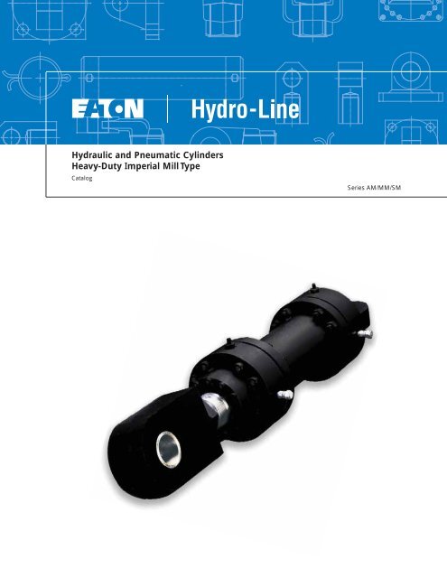
<strong>Hydraulic</strong> <strong>and</strong> <strong>Pneumatic</strong> <strong>Cylinders</strong><br />
<strong>Heavy</strong>-<strong>Duty</strong> <strong>Imperial</strong> <strong>Mill</strong> <strong>Type</strong><br />
Catalog<br />
Series AM/MM/SM
Table of Contents<br />
Design Features........................................................................................................................................................................3<br />
Model Code ..............................................................................................................................................................................4<br />
How to Order............................................................................................................................................................................6<br />
Mounting Style & Installation Dimensions ..........................................................................................................................7<br />
AM Side Lug Foot Mounts..........................................................................................................................................7<br />
GM Head Rectangular Mount ....................................................................................................................................8<br />
CM Cap Clevis Mount ................................................................................................................................................9<br />
SM Spherical Bearing Mount ..................................................................................................................................10<br />
PM Cap Rectangular Mount ......................................................................................................................................11<br />
TM Intermediate Trunnion Mount ............................................................................................................................12<br />
KM No Mount ............................................................................................................................................................13<br />
Mounting Accessories............................................................................................................................................................14<br />
Common Options ..................................................................................................................................................................15<br />
Rod End Selection ....................................................................................................................................................16<br />
Sealing Systems ........................................................................................................................................................17<br />
Port <strong>and</strong> Cushion Selection ......................................................................................................................................18<br />
Application/Engineering Data ..............................................................................................................................................20<br />
Buckling Chart ............................................................................................................................................................20<br />
Threaded Flange Design ..........................................................................................................................................21<br />
2 EATON Hydro-Line <strong>Mill</strong> <strong>Type</strong> Cylinder Series AM/MM/SM H-CYMG-MC001-E June 2007
Design Features<br />
SPECIFICATIONS<br />
Bore Sizes: 2˝ - 16˝<br />
Piston Rod Dia.: 1˝ - 10˝<br />
Pressure Ratings:<br />
MM- 2,000 psi Nominal<br />
<strong>Hydraulic</strong> Service<br />
SM- 3,000 psi Nominal<br />
<strong>Hydraulic</strong> Service<br />
AM- 250 psi <strong>Pneumatic</strong><br />
Service<br />
A. <strong>Heavy</strong> <strong>Duty</strong> Rod<br />
Cartridge<br />
SAE 660 bronze rod cartridge<br />
is pilot-fitted into the<br />
head <strong>and</strong> incorporates<br />
inboard <strong>and</strong> outboard bearing<br />
areas.<br />
Aluminum bronze material<br />
available as an option.<br />
B. Rod Seal <strong>and</strong> Wiper<br />
<strong>Hydraulic</strong>:<br />
High durometer urethane<br />
mechanically loaded rod<br />
seal with a double lip rod<br />
wiper provides contamination<br />
exclusion <strong>and</strong> abrasion<br />
resistance.<br />
High durometer double lip<br />
rod wiper.<br />
Metallic rod scraper available<br />
as an option.<br />
Other rod sealing <strong>and</strong> wiping<br />
systems are available<br />
as options.<br />
<strong>Pneumatic</strong>:<br />
High quality nitrile U-cup<br />
rod seal <strong>and</strong> double-lipped<br />
wiper.<br />
Other rod sealing <strong>and</strong> wiping<br />
systems are available<br />
as options.<br />
F<br />
D<br />
C. Secured Piston<br />
One piece pilot-fitted<br />
ductile iron material.<br />
Piston to rod set screw<br />
staking available as<br />
premium option.<br />
Steel pistons available as<br />
an option with wear b<strong>and</strong>s<br />
or bronze overlay.<br />
D. Piston Seals<br />
<strong>Hydraulic</strong>:<br />
Bi-directional nitrile piston<br />
seal with outboard wearb<strong>and</strong>s<br />
prevents pressure<br />
traps <strong>and</strong> protects against<br />
sideloading.<br />
Other sealing configurations<br />
are available as an<br />
option.<br />
<strong>Pneumatic</strong>:<br />
Bi-directional nitrile piston<br />
seal with outboard wearb<strong>and</strong>s<br />
prevents pressure<br />
traps <strong>and</strong> protects against<br />
sideloading.<br />
Other sealing configurations<br />
are available as an<br />
option.<br />
C<br />
G<br />
E<br />
E. High Yield Piston Rod<br />
High yield, turned, ground<br />
<strong>and</strong> polished C1045/50<br />
microalloy steel.<br />
Hard chrome plated a minimum<br />
of .0006˝ diametrically.<br />
Heavier plating available as<br />
an option, in addition to<br />
various types of stainless<br />
steel <strong>and</strong> chrome over<br />
nickel plated rod material.<br />
F. Cushions<br />
Adjustable design allows<br />
for smooth deceleration;<br />
available for all bore <strong>and</strong><br />
rod combinations, except<br />
on 2.00” bore with 1.375”<br />
rod (rod-end side).<br />
Ball check design allows<br />
for a smooth breakaway<br />
from cushion.<br />
G. High Yield Steel Tubing<br />
<strong>Hydraulic</strong>:<br />
High yield strength steel.<br />
Chrome-plated bores<br />
available as an option.<br />
<strong>Pneumatic</strong>:<br />
High yield strength steel.<br />
Tubes honed & chromeplated<br />
to .0006˝ minimum<br />
diametrically.<br />
Heavier plating available as<br />
an option.<br />
EATON Hydro-Line <strong>Mill</strong> <strong>Type</strong> Cylinder Series AM/MM/SM H-CYMG-MC001-E June 2007<br />
H<br />
F<br />
A<br />
B<br />
H. Body Flanges<br />
Steel construction.<br />
High strength (per ASTM<br />
A574) bolts used for<br />
assembly with hardened<br />
steel washers.<br />
<strong>Hydraulic</strong>: Flanges come<br />
st<strong>and</strong>ard threaded to body<br />
tube for maximum strength<br />
<strong>and</strong> durability. (See<br />
Application Data, page 21.)<br />
<strong>Pneumatic</strong>: Threaded<br />
flanges offered as st<strong>and</strong>ard<br />
for all applications.<br />
3
Model Code<br />
1, 2 <strong>Mill</strong> Cylinder Series<br />
5, 6, 7, 8 Bore<br />
19 Rod End <strong>Type</strong>s<br />
SM – 3000 psi <strong>Hydraulic</strong><br />
MM – 2000 psi <strong>Hydraulic</strong><br />
Specify in inches<br />
(2 position decimal)<br />
02.00 - 2” Dia. Bore<br />
Code - Rod End Style<br />
4 - Short Female UN Thread<br />
AM – 250 psi Pnuematic 03.00 - 3” Dia. Bore<br />
04.00 - 4” Dia. Bore<br />
3, 4 Mounting Style<br />
05.00 - 5” Dia. Bore<br />
AM – Side Lug (Foot)<br />
GM – Head Rectangular<br />
06.00 - 6” Dia. Bore<br />
07.00 - 7” Dia. Bore<br />
08.00 - 8” Dia. Bore<br />
2 - Small Male UN Thread<br />
CM – Clevis Mount<br />
CS – Spherical Mount<br />
10.00 - 10” Dia. Bore<br />
12.00 - 12” Dia. Bore<br />
14.00 - 14” Dia. Bore<br />
5 - Plain - No Attachment<br />
PM – Cap Rectangular 16.00 - 16” Dia. Bore<br />
TM – Intermediate Trunnion<br />
KS – No Mount<br />
AD – Double Rod Side Lug<br />
GD – Double Rod,<br />
Rectangular<br />
TD – Double Rod,<br />
Intermediate Trunnion<br />
KD – Double Rod,<br />
No Mount<br />
XX – Custom<br />
SMGM-05.00x008.00-N-01.38-4-N-P-B-1-1-BP-0<br />
1, 2 3, 4 5, 6, 7, 8 9,10,11,12,13 14 15,16,17,18 19 20 21 22 23,24 25,26<br />
27<br />
9, 10, 11, 12, 13 Stroke<br />
Specify length in inches<br />
(3 positions to the left of<br />
decimal <strong>and</strong> 2 positions to<br />
the right). For example:<br />
Code Size<br />
004.50 4.50<br />
010.00 10<br />
112.50 112.50 etc.<br />
14 Cushions<br />
N - Non-cushioned<br />
B - Cushioned both ends<br />
H - Cushioned head end<br />
C - Cushioned cap end<br />
15, 16, 17, 18 Rod Diameter<br />
Specify in inches<br />
(2 position decimal)<br />
01.00 - 1” Rod Dia.<br />
01.38 - 1.38” Rod Dia.<br />
01.75 - 1.75” Rod Dia.<br />
02.00 - 2” Rod Dia.<br />
02.50 - 2.50” Rod Dia.<br />
03.00 - 3” Rod Dia.<br />
03.50 - 3.50” Rod Dia.<br />
04.25 - 4.25” Rod Dia.<br />
05.00 - 5” Rod Dia.<br />
05.75 - 5.75” Rod Dia.<br />
07.00 - 7” Rod Dia.<br />
08.00 - 8” Rod Dia.<br />
09.00 - 9” Rod Dia.<br />
10.00 -10” Rod Dia.<br />
1 - Int. Male UN Thread<br />
G - Grooved End<br />
K - Extended Small Male UN Thd.<br />
M - Extended Int. Male UN Thread<br />
W - Male Thread (Rod Access.)<br />
X - Custom Rod End<br />
4 EATON Hydro-Line <strong>Mill</strong> <strong>Type</strong> Cylinder Series AM/MM/SM H-CYMG-MC001-E June 2007<br />
All dimensions are in inches.<br />
20 Ports<br />
For maximum reliability,<br />
SAE ports are recommended.<br />
Code - Port Style<br />
N - NPTF<br />
P - Oversize<br />
NPTF<br />
S - SAE<br />
U - Oversize SAE<br />
F - SAE<br />
4-Bolt<br />
Flange<br />
G - BSPP (British<br />
Parallel Thread)<br />
H - Oversize<br />
BSPP<br />
21 Rod Seals<br />
P - Urethane PolyPak<br />
C - Chevron Vee Seals<br />
F - Viton PolyPak<br />
L - Low Friction<br />
Continued on the next page.
Model Code<br />
22 Piston Seals<br />
B - Capped T seals - Nitrile<br />
T - Capped T seals - Viton<br />
R - Cast Iron Rings<br />
X - Special<br />
23,24 Port Locations<br />
1-4 - Head End Position<br />
1-4 - Cap End Position<br />
25,26<br />
Special Modifications<br />
Extra Rod<br />
Extra rod projection<br />
(Inches: 00 to 99)<br />
Item 25 indicates inches from 0 through 9.<br />
Item 26 indicates fractions on an inch per<br />
codes shown below.<br />
Code Fraction Code Fraction<br />
0 - 0 8 - 1/2<br />
1 - 1/16 9 - 9/16<br />
2 - 1/8 A - 5/8<br />
3 - 3/16 B - 11/16<br />
4 - 1/4 C - 3/4<br />
5 - 5/16 D - 13/16<br />
6 - 3/8 E - 7/8<br />
7 - 7/16 F - 15/16<br />
OR<br />
Options (below)<br />
Proximity Switch, Gl<strong>and</strong> Drain,<br />
Air Bleeder, etc.<br />
Bronze Options<br />
BP - Bronze Piston<br />
BS - Bronze/Brass Scraper<br />
Extra Port/Positions<br />
Code Head Cap<br />
EB - 1<br />
EC - 2<br />
ED - 3<br />
EE - 4<br />
EF 1 -<br />
EG 2 -<br />
EH 3 -<br />
EJ 4 -<br />
EK 1 1<br />
EL 1 2<br />
EM 1 3<br />
SMGM-05.00x008.00-N-01.38-4-N-P-B-1-1-BP-0<br />
1, 2 3, 4 5, 6, 7, 8 9,10,11,12,13 14 15,16,17,18 19 20 21 22 23,24 25,26<br />
27<br />
EN 1 4<br />
EP 2 1<br />
ER 2 2<br />
ES 2 3<br />
ET 2 4<br />
EU 3 1<br />
EV 3 2<br />
EW 3 3<br />
EY 3 4<br />
E1 4 1<br />
E2 4 2<br />
E3 4 3<br />
E4 4 4<br />
Gl<strong>and</strong> Drain<br />
G1 - Location 1<br />
G2 - Location 2<br />
G3 - Location 3<br />
G4 - Location 4<br />
Air Bleed/Position<br />
Code Head Cap<br />
HB - 1<br />
HC - 2<br />
HD - 3<br />
HE - 4<br />
HF 1 -<br />
HG 2 -<br />
HH 3 -<br />
HJ 4 -<br />
HK 1 1<br />
HL 1 2<br />
HM 1 3<br />
HN 1 4<br />
HP 2 1<br />
HR 2 2<br />
HS 2 3<br />
HT 2 4<br />
HU 3 1<br />
HV 3 2<br />
HW 3 3<br />
HY 3 4<br />
H1 4 1<br />
H2 4 2<br />
H3 4 3<br />
H4 4 4<br />
Keyed Piston to Rod<br />
KG - Grub Screw<br />
KL - Locknut<br />
KP - Roll Pin<br />
KS - Staked Mechanically<br />
Proximity/Positions<br />
Code Head Cap<br />
PB - 1<br />
PC - 2<br />
PD - 3<br />
PE - 4<br />
PF 1 -<br />
PG 2 -<br />
PH 3 -<br />
PJ 4 -<br />
PK 1 1<br />
PL 1 2<br />
PM 1 3<br />
PN 1 4<br />
PP 2 1<br />
PR 2 2<br />
PS 2 3<br />
PT 2 4<br />
PU 3 1<br />
PV 3 2<br />
PW 3 3<br />
PY 3 4<br />
P1 4 1<br />
P2 4 2<br />
P3 4 3<br />
P4 4 4<br />
Rod Material Options<br />
RC - Ceramic Coated 4140<br />
RH - Case Hardened<br />
RP - Thick Chrome Plate*<br />
RS - Stainless Steel 17-4<br />
RT - Stainless Steel 304**<br />
*.001 Chrome thickness per side<br />
**Consult Factory for pressure rating<br />
Stop Tube/Length (in inches)<br />
Code L Code L<br />
S1 1 S2 2<br />
S3 3 S4 4<br />
S5 5 S6 6<br />
S7 7 S8 8<br />
S9 9 S0 10<br />
SA 11 SB 12<br />
SC 13 SD 14<br />
SE 15 SF 16<br />
SG 17 SH 18<br />
SJ 19 SK 20<br />
27 Custom<br />
X - Special Modifications<br />
EATON Hydro-Line <strong>Mill</strong> <strong>Type</strong> Cylinder Series AM/MM/SM H-CYMG-MC001-E June 2007<br />
All dimensions are in inches.<br />
5
How To Order<br />
St<strong>and</strong>ard <strong>Cylinders</strong> Eaton ® has created an easy<br />
system for ordering Hydro-<br />
Line ® SM Series cylinders.<br />
This system has been developed<br />
to improve our service<br />
to you. The model code<br />
consists of alpha-numeric<br />
digits which fully describe<br />
the most common st<strong>and</strong>ard<br />
options offered on SM<br />
Series cylinders.<br />
To specify your SM Series<br />
cylinder, review the following<br />
pages for a full description<br />
of each option available<br />
<strong>and</strong> select the desired code.<br />
Custom <strong>Cylinders</strong> New <strong>Cylinders</strong><br />
Although the model code<br />
has been arranged to cover<br />
the vast majority of available<br />
options, there will be occasions<br />
when you require an<br />
option which cannot be<br />
coded. When specifying<br />
such an option, enter an “X”<br />
for the appropriate item in<br />
the model code, then<br />
describe your requirements.<br />
For example, if you have an<br />
application which requires a<br />
custom thread on the end of<br />
the piston rod, enter an “X”<br />
for the item. Then add a full<br />
description at the end of the<br />
model code, such as “With<br />
3.25 inch total rod projection<br />
<strong>and</strong> M22 x 1.5 thread 1.375<br />
inches long.” The cylinder<br />
will then be given a unique<br />
five digit design number on<br />
receipt of order (as<br />
explained in next section).<br />
This model code system will:<br />
Simplify the re-order<br />
process.<br />
Each Hydro-Line cylinder is<br />
assigned a model code.<br />
That code is unique to a particular<br />
cylinder description.<br />
That way, when you re-order<br />
your Series SM cylinder,<br />
you’re assured of exactly the<br />
same top quality cylinder<br />
design.<br />
Improve identification.<br />
Every cylinder has its model<br />
code clearly marked on the<br />
product. Each code completely<br />
describes a specific<br />
cylinder. This allows seals<br />
<strong>and</strong> replacement components<br />
to be easily identified in<br />
the field.<br />
Replacement <strong>Cylinders</strong><br />
Every custom Hydro-Line<br />
cylinder is assigned a unique<br />
design number. This number<br />
is contained in the last six<br />
digits of the model code,<br />
<strong>and</strong> item 25 is always an<br />
alpha character. In other<br />
words, the design number<br />
begins where the 'extra rodprojection'<br />
locations (items<br />
25 <strong>and</strong> 26) for custom cylinders.<br />
When ordering a<br />
replacement cylinder, simply<br />
give the model code or the<br />
six digit design number to<br />
your local Hydro-Line<br />
Cylinder Sales representative.<br />
6 EATON Hydro-Line <strong>Mill</strong> <strong>Type</strong> Cylinder Series AM/MM/SM H-CYMG-MC001-E June 2007<br />
Facilitate communications.<br />
This fully descriptive model<br />
code system allows you to<br />
work directly with your local<br />
Eaton sales engineer to<br />
identify <strong>and</strong> service your<br />
Hydro-Line cylinder.<br />
Note: See pages 4 <strong>and</strong> 5 for<br />
a summary of model code<br />
options.<br />
Replacement Parts<br />
Each design number is<br />
stored in a quick retrieval<br />
computerized storage system.<br />
This gives our field<br />
sales representatives rapid<br />
access to assist you in<br />
identifying <strong>and</strong> specifying<br />
genuine Hydro-Line replacement<br />
parts.
Mounting Style<br />
<strong>and</strong> Installation<br />
Dimensions<br />
AM Side Lug (Foot)<br />
Mount<br />
FB,<br />
(4) PLACES<br />
ØE<br />
AMAM/MMAM<br />
TS<br />
US<br />
See page page 16 13 for for Rod Rod Ends Ends<br />
ET AH<br />
1<br />
EE P*<br />
BORE RODS E P* ZE* SS* SW FB US TS ET AH<br />
2 1 <strong>and</strong> 1.375 3.88 3.75 8.13 6.13 .38 .41 5.06 4.25 .63 2.188<br />
3 1.375 <strong>and</strong> 2 5.19 4.25 8.88 7.00 .50 .56 6.56 5.56 .75 2.844<br />
4 1.75 <strong>and</strong> 2.5 6.25 4.50 10.00 7.50 .63 .69 7.88 6.63 1.00 3.375<br />
5 2 <strong>and</strong> 3.5 7.88 5.50 12.88 9.24 .75 .81 9.75 8.25 1.13 4.188<br />
6 2.5 <strong>and</strong> 4 9.25 6.25 14.88 10.88 1.00 1.06 11.63 9.63 1.50 4.875<br />
7 3 <strong>and</strong> 5 10.75 6.38 16.00 11.38 1.13 1.19 13.25 11.13 1.75 5.625<br />
8 3.5 <strong>and</strong> 5.5 12.00 7.75 18.13 13.75 1.25 1.31 14.88 12.38 1.88 6.250<br />
10 4 <strong>and</strong> 5.5 14.94 9.25 20.44 15.75 1.50 1.56 18.31 15.31 2.25 7.781<br />
12 5.5 <strong>and</strong> 7 17.19 10.44 23.25 17.75 1.75 1.81 21.06 17.56 2.63 9.125<br />
14 7 <strong>and</strong> 9 19.50 10.69 25.25 18.50 2.00 2.06 23.88 19.88 3.00 10.500<br />
16 9 <strong>and</strong> 10 23.38 11.19 28.38 20.38 2.25 2.31 28.25 23.75 3.38 12.438<br />
All dimensions are in inches.<br />
SMAM (3000psi)<br />
BORE RODS E P* ZE* SS* SW FB US TS ET AH<br />
3 1.75 <strong>and</strong> 2 5.19 5.38 11.50 8.13 .50 .56 6.56 5.56 .75 2.844<br />
4 2 <strong>and</strong> 2.5 6.50 5.75 12.19 8.75 .63 .69 8.13 6.88 1.00 3.500<br />
5 2.5 <strong>and</strong> 3.5 7.88 7.00 15.25 10.75 .75 .81 9.75 8.25 1.13 4.188<br />
6 3 <strong>and</strong> 4 9.25 7.94 17.56 12.56 1.00 1.06 11.63 9.63 1.50 4.875<br />
7 3.5 <strong>and</strong> 5 10.75 8.63 19.63 13.50 1.13 1.19 13.38 11.13 1.56 5.625<br />
8 4 <strong>and</strong> 5.5 12.38 10.25 22.69 16.25 1.25 1.31 15.38 12.75 1.88 6.438<br />
10 5 <strong>and</strong> 7 14.94 10.50 25.44 17.00 1.50 1.56 18.31 15.31 2.25 7.781<br />
12 5.5 <strong>and</strong> 8 17.50 11.31 27.88 18.63 1.75 2.06 21.63 17.88 2.63 9.125<br />
14 7 <strong>and</strong> 9 20.38 11.56 29.75 19.38 2.00 2.06 24.75 20.75 3.00 10.688<br />
16 9 <strong>and</strong> 10 23.38 12.50 33.75 21.25 2.25 2.31 28.25 23.75 3.38 12.438<br />
All dimensions are in inches.<br />
* Add stroke to these dimensions.<br />
See page 18 for Port Options<br />
EATON Hydro-Line <strong>Mill</strong> <strong>Type</strong> Cylinder Series AM/MM/SM H-CYMG-MC001-E June 2007<br />
ZE*<br />
SS*<br />
SW<br />
(TYP)<br />
7
Mounting Style<br />
<strong>and</strong> Installation<br />
Dimensions<br />
GM Head<br />
Rectangular Mount<br />
AMGM/MMGM<br />
ØBD +.000<br />
(PILOT DIAMETER) -.003<br />
E<br />
R<br />
FB THRU,<br />
(4) PLACES<br />
TE<br />
UF<br />
See See page page 16 13 for for Rod Rod Ends Ends<br />
8 EATON Hydro-Line <strong>Mill</strong> <strong>Type</strong> Cylinder Series AM/MM/SM H-CYMG-MC001-E June 2007<br />
ØE<br />
1<br />
1/8<br />
EE P*<br />
WA F<br />
BORE RODS E P* ZF* F FB R TE UF BD WA<br />
2 1 <strong>and</strong> 1.375 3.88 3.75 7.38 1.50 .41 3.13 4.25 5.00 3.875 2.13<br />
3 1.375 <strong>and</strong> 2 5.19 4.25 7.88 1.63 .56 4.19 5.75 6.75 5.187 2.00<br />
4 1.75 <strong>and</strong> 2.5 6.25 4.50 8.75 1.63 .69 5.00 6.94 8.19 6.250 2.63<br />
5 2 <strong>and</strong> 3.5 7.88 5.50 11.38 2.13 .81 6.38 8.69 10.19 7.875 3.75<br />
6 2.5 <strong>and</strong> 4 9.25 6.25 12.88 2.50 1.06 7.25 10.31 12.31 9.250 4.13<br />
7 3 <strong>and</strong> 5 10.75 6.38 13.63 2.50 1.19 8.38 11.94 14.19 10.750 4.75<br />
8 3.5 <strong>and</strong> 5.5 12.00 7.75 15.63 3.38 1.31 9.50 13.94 15.81 12.000 4.50<br />
10 4 <strong>and</strong> 5.5 14.94 9.25 17.44 3.38 1.56 11.94 16.50 19.50 14.937 4.81<br />
12 5.5 <strong>and</strong> 7 17.19 10.44 19.75 3.69 1.81 13.69 19.00 22.50 17.187 5.63<br />
14 7 <strong>and</strong> 9 19.50 10.69 21.50 3.69 2.06 15.50 21.56 25.56 19.500 7.13<br />
16 9 <strong>and</strong> 10 23.38 11.19 23.88 4.13 2.31 18.88 25.69 30.19 23.375 8.13<br />
All dimensions are in inches.<br />
SMGM (3000psi)<br />
BORE RODS E P* ZF* F FB R TE UF BD WA<br />
3 1.75 <strong>and</strong> 2 5.19 5.38 10.50 1.63 .56 4.19 5.75 6.75 5.187 3.50<br />
4 2 <strong>and</strong> 2.5 6.50 5.75 10.94 1.63 .69 5.25 7.19 8.44 6.50 3.56<br />
5 2.5 <strong>and</strong> 3.5 7.88 7.00 13.75 2.13 .81 6.38 8.69 10.19 7.875 4.63<br />
6 3 <strong>and</strong> 4 9.25 7.94 15.56 2.50 1.06 7.25 10.31 12.31 9.250 5.13<br />
7 3.5 <strong>and</strong> 5 10.75 8.63 17.38 2.50 1.19 8.50 11.94 14.19 10.750 6.25<br />
8 4 <strong>and</strong> 5.5 12.38 10.25 20.19 3.38 1.31 9.88 13.69 16.19 12.375 6.56<br />
10 5 <strong>and</strong> 7 14.94 10.50 21.44 3.38 1.56 11.94 16.50 19.50 14.937 8.56<br />
12 5.5 <strong>and</strong> 8 17.50 11.31 24.38 3.69 1.81 14.00 19.31 22.81 17.50 9.38<br />
14 7 <strong>and</strong> 9 20.38 11.56 25.75 3.69 2.06 16.38 22.44 26.44 20.375 10.50<br />
16 9 <strong>and</strong> 10 23.38 12.50 29.25 4.13 2.31 18.88 25.69 25.69 23.375 12.63<br />
All dimensions are in inches.<br />
* Add stroke to these dimensions.<br />
See page 18 for Port Options<br />
ZF*
Mounting Style<br />
<strong>and</strong> Installation<br />
Dimensions<br />
CM Cap Clevis<br />
Mount<br />
See<br />
See<br />
page<br />
page<br />
16<br />
13<br />
for<br />
for<br />
Rod<br />
Rod<br />
Ends<br />
Ends<br />
AMCM/MMCM<br />
1.00<br />
EE P*<br />
XC*<br />
L<br />
CD<br />
M<br />
CW<br />
(TYP)<br />
(TYP)<br />
BORE RODS E P* XC* M CD L CW CB<br />
2 1 <strong>and</strong> 1.375 3.88 3.75 8.63 .75 .750 1.25 .63 1.25<br />
3 1.375 <strong>and</strong> 2 5.19 4.25 9.38 1.00 1.000 1.50 .75 1.50<br />
4 1.75 <strong>and</strong> 2.5 6.25 4.50 10.88 1.38 1.375 2.12 1.00 2.00<br />
5 2 <strong>and</strong> 3.5 7.88 5.50 13.63 1.75 1.750 2.25 1.25 2.50<br />
6 2.5 <strong>and</strong> 4 9.25 6.25 15.38 2.00 2.000 2.50 1.25 2.50<br />
7 3 <strong>and</strong> 5 10.75 6.38 16.63 2.50 2.500 3.00 1.50 3.00<br />
8 3.5 <strong>and</strong> 5.5 12.00 7.75 18.88 3.00 3.000 3.25 1.50 3.00<br />
10 4 <strong>and</strong> 5.5 14.94 9.25 21.44 3.50 3.500 4.00 2.00 4.00<br />
12 5.5 <strong>and</strong> 7 17.19 10.44 24.25 4.00 4.000 4.50 2.25 4.50<br />
14 7 <strong>and</strong> 9 19.50 10.69 27.25 5.00 5.000 5.75 3.00 6.00<br />
16 9 <strong>and</strong> 10 23.38 11.63 30.88 6.00 6.000 7.00 3.50 7.00<br />
All dimensions are in inches.<br />
SMCM (3000psi)<br />
BORE RODS E P* XC* M CD L CW CB<br />
3 1.75 <strong>and</strong> 2 5.19 5.38 12.00 1.00 1.000 1.50 .75 1.50<br />
4 2 <strong>and</strong> 2.5 6.50 5.75 13.06 1.38 1.375 2.13 1.00 2.00<br />
5 2.5 <strong>and</strong> 3.5 7.88 7.00 16.00 1.75 1.750 2.25 1.25 2.50<br />
6 3 <strong>and</strong> 4 9.25 7.94 18.06 2.00 2.000 2.50 1.25 2.50<br />
7 3.5 <strong>and</strong> 5 10.75 8.63 20.38 2.50 2.500 3.00 1.50 3.00<br />
8 4 <strong>and</strong> 5.5 12.38 10.25 23.44 3.00 3.000 3.25 1.50 3.00<br />
10 5 <strong>and</strong> 7 14.94 10.50 26.44 3.50 3.500 4.00 2.00 4.00<br />
12 5.5 <strong>and</strong> 8 17.50 11.31 28.88 4.00 4.000 4.50 2.25 4.50<br />
14 7 <strong>and</strong> 9 20.38 11.56 31.50 5.00 5.000 5.75 3.00 6.00<br />
16 9 <strong>and</strong> 10 23.38 12.50 36.25 6.00 6.000 7.00 3.50 7.00<br />
All dimensions are in inches.<br />
* Add stroke to these dimensions.<br />
See page 18 for Port Options<br />
EATON Hydro-Line <strong>Mill</strong> <strong>Type</strong> Cylinder Series AM/MM/SM H-CYMG-MC001-E June 2007<br />
CB<br />
ØE<br />
9
Mounting Style<br />
<strong>and</strong> Installation<br />
Dimensions<br />
CS Spherical<br />
Bearing Mount<br />
AMCS/MMCS<br />
See See page page 16 13 for for Rod Rod Ends Ends<br />
1<br />
EE P*<br />
10 EATON Hydro-Line <strong>Mill</strong> <strong>Type</strong> Cylinder Series AM/MM/SM H-CYMG-MC001-E June 2007<br />
L<br />
XC* CK<br />
BORE RODS E P* XC* M CD L CK<br />
2 1 <strong>and</strong> 1.375 3.88 3.75 8.63 1.25 .750 1.25 .56<br />
3 1.375 <strong>and</strong> 2 5.19 4.25 9.38 1.63 1.000 1.50 1.00<br />
4 1.75 <strong>and</strong> 2.5 6.25 4.50 10.88 1.75 1.375 2.13 1.50<br />
5 2 <strong>and</strong> 3.5 7.88 5.50 13.63 2.50 1.750 2.25 1.75<br />
6 2.5 <strong>and</strong> 4 9.25 6.25 15.38 2.88 2.000 2.50 2.00<br />
7 3 <strong>and</strong> 5 10.75 6.38 16.63 3.38 2.500 3.00 2.50<br />
8 3.5 <strong>and</strong> 5.5 12.00 7.75 18.88 3.88 3.000 3.25 3.00<br />
10 4 <strong>and</strong> 5.5 14.94 9.25 21.44 5.50 3.500 4.00 3.19<br />
12 5.5 <strong>and</strong> 7 17.19 10.44 24.25 6.00 4.000 4.50 3.50<br />
14 7 <strong>and</strong> 9 19.50 10.69 27.25 6.75 5.000 5.75 4.25<br />
16 9 <strong>and</strong> 10 23.38 11.63 30.88 7.50 6.000 7.00 4.63<br />
All dimensions are in inches.<br />
SMCS (3000psi)<br />
BORE RODS E P* XC* M CD L CK<br />
3 1.75 <strong>and</strong> 2 5.19 5.38 12.00 1.63 1.000 1.50 1.00<br />
4 2 <strong>and</strong> 2.5 6.50 5.75 13.06 1.75 1.375 2.13 1.50<br />
5 2.5 <strong>and</strong> 3.5 7.88 7.00 16.00 2.50 1.750 2.25 1.75<br />
6 3 <strong>and</strong> 4 9.25 7.94 18.06 2.88 2.000 2.50 2.00<br />
7 3.5 <strong>and</strong> 5 10.75 8.63 20.38 3.38 2.500 3.00 2.50<br />
8 4 <strong>and</strong> 5.5 12.38 10.25 23.44 3.88 3.000 3.25 3.00<br />
10 5 <strong>and</strong> 7 14.94 10.50 26.44 5.50 3.500 4.00 3.19<br />
12 5.5 <strong>and</strong> 8 17.50 11.31 28.88 6.00 4.000 4.50 3.50<br />
14 7 <strong>and</strong> 9 20.38 11.56 31.50 6.75 5.000 5.75 4.25<br />
16 9 <strong>and</strong> 10 23.38 12.50 36.25 7.50 6.000 7.00 4.63<br />
All dimensions are in inches.<br />
* Add stroke to these dimensions.<br />
See page 18 for Port Options<br />
CD<br />
M<br />
ØE
Mounting Style<br />
<strong>and</strong> Installation<br />
Dimensions<br />
PM Cap<br />
Rectangular Mount<br />
See<br />
See<br />
page<br />
page<br />
16<br />
13<br />
for<br />
for<br />
Rod<br />
Rod<br />
Ends<br />
Ends<br />
AMPM/MMPM<br />
1<br />
EE P*<br />
ZF*<br />
F<br />
.125<br />
ØBD +.000<br />
(PILOT DIAMETER) -.003<br />
E<br />
FB THRU,<br />
(4) PLACES<br />
BORE RODS E P* ZF* F FB R TE UF BD<br />
2 1 <strong>and</strong> 1.375 3.88 3.75 7.38 1.50 .41 3.13 4.25 5.00 3.875<br />
3 1.375 <strong>and</strong> 2 5.19 4.25 7.88 1.63 .56 4.19 5.75 6.75 5.187<br />
4 1.75 <strong>and</strong> 2.5 6.25 4.50 8.75 1.63 .69 5.00 6.94 8.19 6.250<br />
5 2 <strong>and</strong> 3.5 7.88 5.50 11.38 2.13 .81 6.38 8.69 10.19 7.875<br />
6 2.5 <strong>and</strong> 4 9.25 6.25 12.88 2.50 1.06 7.25 10.31 12.31 9.250<br />
7 3 <strong>and</strong> 5 10.75 6.38 13.63 2.50 1.19 8.38 11.94 14.19 10.750<br />
8 3.5 <strong>and</strong> 5.5 12.00 7.75 15.63 3.38 1.31 9.50 13.94 15.81 12.000<br />
10 4 <strong>and</strong> 5.5 14.94 9.25 17.44 3.38 1.56 11.94 16.50 19.50 14.937<br />
12 5.5 <strong>and</strong> 7 17.19 10.44 19.75 3.69 1.81 13.69 19.00 22.50 17.187<br />
14 7 <strong>and</strong> 9 19.50 10.69 21.50 3.69 2.06 15.50 21.56 25.56 19.500<br />
16 9 <strong>and</strong> 10 23.38 11.19 23.88 4.13 2.31 18.88 25.69 30.19 23.000<br />
All dimensions are in inches.<br />
SMPM (3000psi)<br />
BORE RODS E P* ZF* F FB R TE UF BD<br />
3 1.75 <strong>and</strong> 2 5.19 5.38 10.50 1.63 .56 4.19 5.75 6.75 5.187<br />
4 2 <strong>and</strong> 2.5 6.50 5.75 10.94 1.63 .69 5.25 7.19 8.44 6.50<br />
5 2.5 <strong>and</strong> 3.5 7.88 7.00 13.75 2.13 .81 6.38 8.69 10.19 7.875<br />
6 3 <strong>and</strong> 4 9.25 7.94 15.56 2.50 1.06 7.25 10.31 12.31 9.250<br />
7 3.5 <strong>and</strong> 5 10.75 8.63 17.38 2.50 1.19 8.50 11.94 14.19 10.750<br />
8 4 <strong>and</strong> 5.5 12.38 10.25 20.19 3.38 1.31 9.88 13.69 16.19 12.375<br />
10 5 <strong>and</strong> 7 14.94 10.50 21.44 3.38 1.56 11.94 16.50 19.50 14.937<br />
12 5.5 <strong>and</strong> 8 17.50 11.31 24.38 3.69 1.81 14.00 19.31 22.81 17.50<br />
14 7 <strong>and</strong> 9 20.38 11.56 25.75 3.69 2.06 16.38 22.44 26.44 20.375<br />
16 9 <strong>and</strong> 10 23.38 12.50 29.25 4.13 2.31 18.88 25.69 30.19 23.375<br />
All dimensions are in inches.<br />
* Add stroke to these dimensions.<br />
See page 18 for Port Options<br />
EATON Hydro-Line <strong>Mill</strong> <strong>Type</strong> Cylinder Series AM/MM/SM H-CYMG-MC001-E June 2007<br />
R<br />
TE<br />
UF<br />
ØE<br />
11
Mounting Style<br />
<strong>and</strong> Installation<br />
Dimensions<br />
TM Intermediate<br />
Trunnion Mount<br />
TD<br />
(TYP)<br />
AMTM/MMTM<br />
ØE<br />
TM<br />
TL<br />
(TYP)<br />
See<br />
See<br />
page<br />
page<br />
16<br />
13<br />
for<br />
for<br />
Rod<br />
Rod<br />
Ends<br />
Ends<br />
BORE RODS E P* ZF* TD TL TM<br />
2 1 <strong>and</strong> 1.375 3.88 3.75 7.38 1.25 1.25 3.94<br />
3 1.375 <strong>and</strong> 2 5.19 4.25 7.88 1.50 1.50 5.25<br />
4 1.75 <strong>and</strong> 2.5 6.25 4.50 8.75 2.00 2.00 6.31<br />
5 2 <strong>and</strong> 3.5 7.88 5.50 11.38 2.50 2.50 7.94<br />
6 2.5 <strong>and</strong> 4 9.25 6.25 12.88 3.00 3.00 9.31<br />
7 3 <strong>and</strong> 5 10.75 6.38 13.63 3.50 3.50 10.81<br />
8 3.5 <strong>and</strong> 5.5 12.00 7.75 15.63 4.00 4.00 12.06<br />
10 4 <strong>and</strong> 5.5 14.94 9.25 17.44 5.00 5.00 15.00<br />
12 5.5 <strong>and</strong> 7 17.19 10.44 19.75 6.00 6.00 17.25<br />
14 7 <strong>and</strong> 9 19.50 10.69 21.50 7.00 7.00 19.56<br />
16 9 <strong>and</strong> 10 23.38 11.625 23.88 8.00 8.00 23.44<br />
All dimensions are in inches.<br />
SMTM (3000psi)<br />
BORE RODS E P* ZF* TD TL TM<br />
3 1.75 <strong>and</strong> 2 5.19 5.38 10.50 1.50 1.50 5.25<br />
4 2 <strong>and</strong> 2.5 6.50 5.75 10.94 2.00 2.00 6.56<br />
5 2.5 <strong>and</strong> 3.5 7.88 7.00 13.75 2.50 2.50 7.94<br />
6 3 <strong>and</strong> 4 9.25 7.94 15.56 3.00 3.00 9.31<br />
7 3.5 <strong>and</strong> 5 10.75 8.63 17.38 3.50 3.50 10.81<br />
8 4 <strong>and</strong> 5.5 12.38 10.25 20.19 4.00 4.00 12.44<br />
10 5 <strong>and</strong> 7 14.94 10.50 21.44 5.00 5.00 15.00<br />
12 5.5 <strong>and</strong> 8 17.50 11.31 24.38 7.50 7.50 17.56<br />
14 7 <strong>and</strong> 9 20.38 11.56 25.75 8.50 8.50 20.44<br />
16 9 <strong>and</strong> 10 23.38 12.50 29.25 9.50 9.50 23.44<br />
All dimensions are in inches.<br />
* Add stroke to these dimensions.<br />
12 EATON Hydro-Line <strong>Mill</strong> <strong>Type</strong> Cylinder Series AM/MM/SM H-CYMG-MC001-E June 2007<br />
1<br />
See page 18 for Port Options<br />
EE P*<br />
XI*<br />
ZF*
Mounting Style<br />
<strong>and</strong> Installation<br />
Dimensions<br />
KS Basic<br />
No Mount<br />
AMKS/MMKS<br />
ØMM<br />
BORE RODS E P* ZF*<br />
2 1 <strong>and</strong> 1.375 3.88 3.75 7.38<br />
3 1.375 <strong>and</strong> 2 5.19 4.25 7.88<br />
4 1.75 <strong>and</strong> 2.5 6.25 4.50 8.75<br />
5 2 <strong>and</strong> 3.5 7.88 5.50 11.38<br />
6 2.5 <strong>and</strong> 4 9.25 6.25 12.88<br />
7 3 <strong>and</strong> 5 10.75 6.38 13.63<br />
8 3.5 <strong>and</strong> 5.5 12.00 7.75 15.63<br />
10 4 <strong>and</strong> 5.5 14.94 9.25 17.44<br />
12 5.5 <strong>and</strong> 7 17.19 10.44 19.75<br />
14 7 <strong>and</strong> 9 19.50 10.69 21.50<br />
16 9 <strong>and</strong> 10 23.38 11.63 23.88<br />
All dimensions are in inches.<br />
SMKS (3000psi)<br />
BORE RODS E P* ZF*<br />
3 1.75 <strong>and</strong> 2 5.19 5.38 10.50<br />
4 2 <strong>and</strong> 2.5 6.50 5.75 10.94<br />
5 2.5 <strong>and</strong> 3.5 7.88 7.00 13.75<br />
6 3 <strong>and</strong> 4 9.25 7.94 15.56<br />
7 3.5 <strong>and</strong> 5 10.75 8.63 17.38<br />
8 4 <strong>and</strong> 5.5 12.38 10.25 20.19<br />
10 5 <strong>and</strong> 7 14.94 10.50 21.44<br />
12 5.5 <strong>and</strong> 8 17.50 11.31 24.38<br />
14 7 <strong>and</strong> 9 20.38 11.56 25.75<br />
16 9 <strong>and</strong> 10 23.38 12.50 29.25<br />
All dimensions are in inches.<br />
* Add stroke to these dimensions.<br />
ØE<br />
See page 16 for Rod Ends<br />
See page 13 for Rod Ends<br />
1<br />
See page 18 for Port Options<br />
EE P*<br />
EATON Hydro-Line <strong>Mill</strong> <strong>Type</strong> Cylinder Series AM/MM/SM H-CYMG-MC001-E June 2007<br />
ZF*<br />
13
Mounting<br />
Accessories<br />
All rod accessories must be<br />
torqued against the rod<br />
shoulder. Mounting brackets,<br />
rod clevises, <strong>and</strong> rod<br />
eyes for all Series SM<br />
cylinders are available<br />
from Eaton.<br />
Rod Eye<br />
ER<br />
CD +.004<br />
+.002<br />
Rod Clevis<br />
CD CD<br />
ER Radius<br />
Pivot Pin<br />
L<br />
CE<br />
A<br />
CD<br />
CA<br />
CB<br />
CW CB CW<br />
KK Tap<br />
CD CL<br />
These accessories are<br />
detailed below showing part<br />
numbers <strong>and</strong> all pertinent<br />
dimensional data. Make<br />
sure the rod end type<br />
selected has threads that<br />
match the threads of any<br />
required accessory.<br />
KK Tap<br />
NOTE: CL = 2 x CW + CB<br />
CD +.004<br />
+.002<br />
CH Hex<br />
Across Flats<br />
NOTES:<br />
1. The load listed is max load in tension.<br />
2. The pull load of the cylinder should be less than the listed load for the respective<br />
selected rod accessory.<br />
3. Pivot pin is rated in shear.<br />
4. The Accessories selection chart on page 14 is only a guide, select the accessories taking<br />
into consideration the pull load of the cylinder <strong>and</strong> the rated load of the accessory.<br />
5. All rod accessories must be torqued against rod shoulder.<br />
CP<br />
Dimensions are in inches<br />
unless otherwise noted.<br />
When ordering, please specify<br />
the part name <strong>and</strong> part<br />
number.<br />
14 EATON Hydro-Line <strong>Mill</strong> <strong>Type</strong> Cylinder Series AM/MM/SM H-CYMG-MC001-E June 2007<br />
PART NUMBER A CA CB CD ER KK<br />
STATIC<br />
TENSILE<br />
LOAD (LB)<br />
C-9304 1.13 2.06 1.25 0.75 0.88 .750-16 10,750<br />
C-93065 1.63 2.81 1.50 1.00 1.19 1.000-14 16,500<br />
C-9308 2.00 3.44 2.00 1.38 1.56 1.250-12 30,500<br />
C-9310 2.25 4.00 2.50 1.75 2.00 1.500-12 47,500<br />
C-9312 3.00 5.00 2.50 2.00 2.25 1.875-12 55,000<br />
C-9314 3.50 5.81 3.00 2.50 2.81 2.250-12 80,000<br />
C-9316 3.50 6.13 3.00 3.00 3.25 2.500-12 94,000<br />
C-9320 4.50 7.63 4.00 3.50 3.88 3.250-12 158,200<br />
C-9324 5.50 9.13 4.50 4.00 4.44 4.000-12 211,500<br />
C-9328A 7.00 11.75 6.00 5.00 5.25 5.500-12 337,500<br />
C-9332A 9.00 14.25 7.00 6.00 6.25 6.000-12 450,000<br />
PART<br />
STATIC<br />
TENSILE<br />
NUMBER CB CD CE CH CW ER KK L LOAD (LB)<br />
C-134-08 1.25 0.75 2.38 1.38 0.63 0.75 .750-16 1.25 9,750<br />
C-134-11 1.50 1.00 3.13 1.63 0.75 1.00 1.000-14 1.50 17,500<br />
C-134-14 2.00 1.38 4.13 2.00 1.00 1.38 1.250-12 2.13 28,000<br />
C-134-16 2.50 1.75 4.50 2.38 1.25 1.75 1.500-12 2.25 45,500<br />
C-134-20 2.50 2.00 5.50 2.94 1.25 2.00 1.875-12 2.50 52,000<br />
C-134-24 3.00 2.50 6.50 3.50 1.50 2.50 2.250-12 3.00 78,000<br />
C-134-28 3.00 3.00 6.75 3.88 1.50 2.75 2.500-12 3.25 75,000<br />
C-134-36 4.00 3.50 8.50 5.00 2.00 3.50 3.250-12 4.00 142,500<br />
C-134-44 4.50 4.00 10.00 6.13 2.25 4.00 4.000-12 4.50 182,500<br />
C-134-50 6.00 5.00 12.75 - 3.00 5.25 5.500-12 5.75 300,000<br />
C-134-58 7.00 6.00 15.75 - 3.50 6.25 6.000-12 6.75 390,000<br />
PART NUMBER CD CL CP<br />
STATIC<br />
SHEAR<br />
LOAD (LB)<br />
C-9004-3 0.750 2.50 3.13 18,425<br />
C-90065-3 1.000 3.00 3.75 32,775<br />
C-9008-3 1.375 4.00 4.75 62,000<br />
C-9010-3 1.750 5.00 6.03 100,425<br />
C-9012-3 2.000 5.00 6.03 131,175<br />
C-9014-3 2.500 6.00 7.03 204,975<br />
C-9016-3 3.000 6.00 7.13 295,175<br />
C-9020-3 3.500 8.00 9.63 401,775<br />
C-9024-3 4.000 9.00 10.63 524,750<br />
C-9028-3 5.000 12.00 13.63 819,950<br />
C-9032-3 6.000 14.00 15.63 1,180,725
Mounting<br />
Accessories<br />
Eye Bracket: C-8904 to C-8924 Eye Bracket: C-8928 to C-8932<br />
BD Dia<br />
(4) Holes<br />
E<br />
CB<br />
STATIC<br />
TENSILE<br />
PART NUMBER CB CD BD E F FL LR M MR BA A˚ B˚ AA LOAD<br />
C-8904 1.25 0.75 0.53 3.50 0.63 1.88 1.00 0.75 1.06 2.56 - - 3.60 11,000<br />
C-89065X 1.50 1.00 0.66 4.50 0.88 2.38 1.00 1.00 1.13 3.25 - - 4.60 20,000<br />
C-8908 2.00 1.38 0.66 5.00 0.88 3.00 1.25 1.38 1.75 3.81 - - 5.40 22,000<br />
C-8910X 2.50 1.75 0.91 6.50 1.13 3.38 1.75 1.75 1.88 4.95 - - 7.00 49,500<br />
C-8912X 2.50 2.00 1.03 7.50 1.50 4.00 2.00 2.00 2.13 5.75 - - 8.10 62,500<br />
C-8914X 3.00 2.50 1.16 8.50 1.75 4.75 2.50 2.50 2.50 6.59 - - 9.30 90,000<br />
C-8916X 3.00 3.00 1.28 9.50 2.00 5.25 2.75 2.75 2.75 7.50 - - 10.60 105,500<br />
C-8920 4.00 3.50 1.78 12.63 1.69 5.69 3.50 3.50 3.50 9.62 - - 13.60 60,000<br />
C-8924 4.50 4.00 2.03 14.88 1.94 6.44 3.88 3.88 4.00 11.50 - - 16.20 75,000<br />
C-8928 6.00 5.00 1.03 17.25 2.19 7.94 5.00 5.00 5.25 14.41 27.60 11.60 17.31 95,650<br />
C-8932 7.00 6.00 1.28 20.00 2.63 9.38 5.50 6.00 6.25 17.50 22.50 15.00 19.00 187,500<br />
SQ<br />
AABC BA/2<br />
CD +.004<br />
+.002<br />
FL<br />
F<br />
CB<br />
ESQ BABC MR<br />
BD<br />
(20) Holes<br />
FL<br />
F<br />
Accessories<br />
Selection Chart<br />
BA<br />
M<br />
MR<br />
Recommended Torque Values -<br />
using MoS2 lubricant with .12 coefficient of friction<br />
THREAD SIZE TORQUE<br />
ft lbs<br />
.750-16 125<br />
1.000-14 250<br />
1.250-12 460<br />
1.500-12 663<br />
1.875-12 944<br />
2.250-12 1,315<br />
LR<br />
THREAD SIZE TORQUE<br />
ft lbs<br />
2.500-12 5,050<br />
3.250-12 7,940<br />
4.000-12 12,560<br />
5.500-12 16,275<br />
6.000-12 21,600<br />
AA A˚ B˚Typ.<br />
THREAD<br />
THREAD<br />
LENGTH ROD ROD EYE ROD THREAD ROD THREAD<br />
BORE PIN Ø SIZE KK A CLEVIS EYE BRACKET SIZE OPTION SIZE OPTION<br />
MM Series SM Series<br />
2.00 0.750 .750-16 1.13 C-134-08 C-9304 C-8904 1.00 2 - -<br />
3.00 1.000 1.000-14 1.63 C-134-11 C-93065 C-89065X 1.38 2 1.75 W<br />
4.00 1.375 1.250-12 2.00 C-134-14 C-9308 C-8908 1.75 2 2.00 W<br />
5.00 1.750 1.500-12 2.25 C-134-16 C-9310 C-8910X 2.00 2 2.50 W<br />
6.00 2.000 1.875-12 3.00 C-134-20 C-9312 C-8912X 2.50 2 3.00 W<br />
7.00 2.500 2.250-12 3.50 C-134-24 C-9314 C-8914X 3.00 2 3.50 W<br />
8.00 3.000 2.500-12 3.50 C-134-28 C-9316 C-8916X 3.50 2 4.00 W<br />
10.00 3.500 3.250-12 4.50 C-134-36 C-9320 C-8920 5.50 W 5.00 W<br />
12.00 4.000 4.000-12 5.50 C-134-44 C-9324 C-8924 5.50 2 5.50 2<br />
14.00 5.000 5.500-12 7.00 C-134-50 C-9328A C-8928 7.00 2 7.00 2<br />
16.00 6.000 6.000-12 9.00 C-134-58 C-9332A C-8932 9.00 W 9.00 W<br />
CD +.004<br />
+.002<br />
NOTES:<br />
1. The load listed is max load in tension.<br />
2. The pull load of the cylinder should be less than the listed load for the respective<br />
selected rod accessory.<br />
3. Pivot pin is rated in shear.<br />
4. The Accessories selection chart on page 14 is only a guide, select the accessories taking<br />
into consideration the pull load of the cylinder <strong>and</strong> the rated load of the accessory.<br />
5. All rod accessories must be torqued against rod shoulder.<br />
NOTES:<br />
The Accessories selection chart is only a guide, select the accessories taking into consideration the pull load of the cylinder <strong>and</strong> the rated load of the accessory.<br />
EATON Hydro-Line <strong>Mill</strong> <strong>Type</strong> Cylinder Series AM/MM/SM H-CYMG-MC001-E June 2007<br />
LR<br />
15
Common Options<br />
Rod End Selection<br />
In addition to selecting the<br />
correct bore, you must<br />
specify the appropriate rod<br />
size <strong>and</strong> rod end configuration<br />
for your application.<br />
Eight different inch rod end<br />
configurations are available.<br />
If a custom design is<br />
required, contact your local<br />
Eaton Hydro-Line sales engineer,<br />
<strong>and</strong> we will build to<br />
your requirements.<br />
The table on page 20 gives<br />
maximum allowable push<br />
strokes at various operating<br />
pressures for available rod<br />
diameters of Series SM<br />
cylinders.<br />
Code 4 Code 2 Code 5 Code 1<br />
D<br />
MM<br />
KK<br />
1<br />
A<br />
Code G Code K Code M Code W<br />
AF<br />
MM<br />
R1/32<br />
AE<br />
AD<br />
AC<br />
D<br />
MM<br />
D<br />
MM<br />
16 EATON Hydro-Line <strong>Mill</strong> <strong>Type</strong> Cylinder Series AM/MM/SM H-CYMG-MC001-E June 2007<br />
KK<br />
KK<br />
AL<br />
A<br />
1<br />
1<br />
MM<br />
CC<br />
1<br />
D<br />
MM AX<br />
1<br />
Rod ends on rigid mount<br />
cylinders should be supported.<br />
Longer strokes are<br />
allowable for pull only applications.<br />
Contact your local<br />
Eaton Hydro-Line sales engineer<br />
for application assistance<br />
if necessary.<br />
ROD Ø<br />
MM A AC AD AE AF AL AM AX CC D* KK A1 KK1<br />
1 1.13 1.50 .94 .375 .688 1.56 1.50 1.94 .875-14 .875 . 750-16 - -<br />
1.375 1.63 1.75 1.06 .375 .875 2.19 2.00 2.75 1.250-12 1.125 1.000-14 - -<br />
1.75 2.00 1.75 1.31 .500 1.125 2.75 2.25 3.13 1.500-12 1.500 1.250-12 1.63 1.000-14<br />
2 2.25 2.63 1.69 .625 1.375 3.13 3.00 4.13 1.750-12 1.688 1.500-12 2.00 1.250-12<br />
2.5 3.00 3.25 1.94 .750 1.750 4.13 3.50 4.75 2.250-12 2.062 1.875-12 2.25 1.500-12<br />
3 3.50 3.63 2.44 .875 2.250 4.75 3.50 5.50 2.750-12 2.625 2.250-12 3.00 1.875-12<br />
3.5 3.50 4.38 2.69 1.000 2.500 5.00 4.50 6.38 3.250-12 3.000 2.500-12 3.50 2.250-12<br />
4 4.00 4.50 2.69 1.000 3.000 5.63 4.50 6.56 3.750-12 - 3.000-12 3.50 2.500-12<br />
4.5 4.50 4.50 2.69 1.000 3.000 6.38 5.00 7.31 3.750-12 - 3.250-12 - -<br />
5 5.00 5.38 3.19 1.500 3.875 7.00 5.00 7.56 4.750-12 - 3.500-12 4.50 3.250-12<br />
5.5 5.50 6.25 3.94 1.875 4.375 7.75 6.75 9.56 5.250-12 - 4.000-12 4.50 3.250-12<br />
7 7.00 6.50 4.06 2.000 5.750 10.00 7.00 10.50 6.500-12 - 5.500-12 - -<br />
8 8.00 6.50 4.06 2.000 6.500 11.25 8.00 12.00 7.500-12 - 6.000-12 - -<br />
9 9.00 6.75 4.13 2.000 7.250 12.50 9.00 13.50 8.500-12 - 6.500-12 9.00 6.000-12<br />
10 10.00 7.25 4.63 2.375 8.000 14.00 10.00 15.13 9.500-12 - 7.250-12 - -<br />
NOTE:<br />
1. Dimensions in inches.<br />
*2. Wrench flats for rods less than 4”, larger rods will have 2 spanner holes 180˚ apart.<br />
**3. Thread option “W” should only be used for rod accessories.<br />
D<br />
MM<br />
MM<br />
CC<br />
KK1<br />
AM<br />
A1<br />
1
Common Options<br />
Section<br />
Sealing Systems<br />
Four different sealing systems<br />
are available in Series<br />
SM cylinders.<br />
Determine the correct seal<br />
code for your application,<br />
then enter it in the model<br />
code.<br />
Available Sealing<br />
System Combinations Rod Seal Code Piston Seal Code<br />
N - Normal Seals P B<br />
L - Low Friction L B<br />
T - High Temperature F T<br />
C-Classic (Cheveron/C.I. Rings) C R<br />
Rod Seals (Position 21)<br />
P - Urethane PolyPak<br />
C - Chevron Vee Seals<br />
F - Viton PolyPak<br />
L - Low Friction<br />
Piston Seals (Position 22)<br />
B - Capped T seals - Nitrile<br />
T - Capped T seals - Viton<br />
R - Cast Iron Rings<br />
X - Special<br />
Seal Code Rod Seal Configuration Piston Seal Configuration Temp ˚F Seal Material Fluid Application<br />
N Polypak seal (1) Capped T-Seal (1) -20 to 200 Urethane Petroleum based oil Normal<br />
Buffer Seal (1) Wearb<strong>and</strong>s PTFE Mineral based oil Typical Industrial<br />
Wiper (1) Nitrile Water in oil emulsions<br />
L Buffer Seal (2) Capped T-Seal (1) -20 to 200 PTFE Petroleum based oil Low friction servo<br />
Wiper (1) Wearb<strong>and</strong>s Nitrile Mineral based oil<br />
Water in oil emulsions<br />
T Polypak Seal (1) Capped T-Seal (1) -20 to 400 Flurocarbon Petroleum based oil High Temperature<br />
Buffer Seal (1) Wearb<strong>and</strong>s PTFE Mineral based oils<br />
Wiper (1) Water under 150˚ F<br />
Phosphate esters<br />
C Chevron Cast Iron Rings -20 to 200 Nitrile Petroleum based oil Normal<br />
Mineral based oil Typical Industrial<br />
ROD SEAL CONFIGURATION<br />
N <strong>and</strong> T Seal Options<br />
L Seal Option<br />
PISTON SEAL CONFIGURATION<br />
N, L <strong>and</strong> T Seal Options<br />
EATON Hydro-Line <strong>Mill</strong> <strong>Type</strong> Cylinder Series AM/MM/SM H-CYMG-MC001-E June 2007<br />
17
Common Options<br />
Port <strong>and</strong> Cushion<br />
Selection<br />
Port Code N <strong>and</strong> P Port Code S <strong>and</strong> U<br />
Port Code G <strong>and</strong> H<br />
Port Code F Z (4 Places)<br />
A Dia.<br />
Port Code F Reference Table<br />
FLANGE SIZE A Q W X Z GG<br />
W<br />
Q +/- .010<br />
GG +/- .010<br />
SAE J1926 UN Thread SAE 518<br />
in. NPTF* Pipe O-Ring/Thread Size Code 61 Flange ISO 228-1 BSPP*<br />
2 1/2 3/4 #6 #8 - 1/2 -<br />
3 1/2 3/4 #8 #12 - 1/2 3/4<br />
4 3/4 1 #10 #12 1/2 (-8) 1/2 3/4<br />
5 3/4 1 #12 #16 3/4 (-12) 1/2 3/4<br />
6 1 1-1/4 #16 #20 1 (-16) 3/4 1<br />
7 1-1/4 1-1/2 #16 #20 1-1/4 (-20) 1 1-1/4<br />
8 1-1/2 2 #24 #32 1-1/2 (-24) 1-1/4 1-1/2<br />
10 2 - #32 - 2 (-32) 2 -<br />
12<br />
14<br />
2-1/2<br />
2-1/2<br />
1<br />
-<br />
-<br />
#32<br />
#32<br />
-<br />
-<br />
2-1/2 (-40)<br />
2-1/2 (-40)<br />
2-1/2<br />
2-1/2<br />
-<br />
-<br />
16 3 - #32 - 3 (-48) 3 -<br />
SM Series<br />
PORT CODE<br />
BORE Ø N P S U F G H<br />
4<br />
SAE J1926 2 UN Thread SAE 518<br />
in. NPTF* Pipe O-Ring/Thread Size Code 61 Flange ISO 228-1 BSPP*<br />
3 1/2 3/4 #6 #8 - 1/2 3/4<br />
4 1/2 3/4 #10 #12 1/2 (-8) 1/2 3/4<br />
5 3/4 1 #12 #16 3/4 (-12) 1/2 3/4<br />
6 1 1-1/4 #16 #20 1 (-16) 3/4 1<br />
7<br />
8<br />
1<br />
1-1/2<br />
3<br />
1-1/4<br />
2<br />
#16<br />
#20<br />
#20<br />
#24<br />
1-1/4 (-20)<br />
1-1/2 (-24)<br />
1<br />
1-1/4<br />
1-1/4<br />
1-1/2<br />
10 2 - #32 - 2 (-32) 2 -<br />
12 2-1/2 - #32 - 2-1/2 (-40) 2-1/2 -<br />
14 2-1/2 - #32 - 2-1/2 (-40) 2-1/2 -<br />
16 3 - #32 - 3 (-48) 3 -<br />
18 EATON Hydro-Line <strong>Mill</strong> <strong>Type</strong> Cylinder Series AM/MM/SM H-CYMG-MC001-E June 2007<br />
X<br />
1/2 (-8) 0.50 1.500 0.750 0.344 5/16-18 0.688<br />
3/4 (-12) 0.75 1.875 0.938 0.438 3/8-16 0.875<br />
1 (-16) 1.00 2.062 1.031 0.515 3/8-16 1.031<br />
1-1/4 (-20) 1.25 2.312 1.156 0.594 7/16-14 1.188<br />
1-1/2 (-24) 1.50 2.750 1.375 0.703 1/2-13 1.406<br />
2 (-32) 2.00 3.062 1.531 0.844 1/2-13 1.688<br />
2-1/2 (-40) 2.50 3.500 1.750 1.000 1/2-13 2.000<br />
3 (48) 3.00 4.188 2.094 1.217 5/8-11 2.438<br />
AM, MM Series<br />
PORT CODE<br />
BORE Ø N P S U F G H<br />
*NPTF <strong>and</strong> BSPP ports are not recommended for maximum reliability on new applications.
Common Options<br />
Port <strong>and</strong> Cushion<br />
Selection<br />
Port <strong>and</strong> cushion locations<br />
are identified by viewing the<br />
cylinder from the head end<br />
(or from the mounting end<br />
of double rod cylinder). The<br />
location numbers are shown<br />
to the right.<br />
Certain port <strong>and</strong> cushion<br />
locations cannot be specified<br />
with some mounting<br />
styles. The table below indicates<br />
which of the head <strong>and</strong><br />
cap port location are available<br />
for each Series SM<br />
mounting style.<br />
Port Location Availability Chart<br />
MOUNTING HEAD LOCATION CAP LOCATION<br />
STYLE CODE DESCRIPTION 1 2 3 4 1 2 3 4<br />
AM Side Lug A A N A A A N A<br />
GM Head Rectangular A A A A A A A A<br />
CM Cap Clevis A A A A A A A A<br />
CS Spherical Bearing A A A A A A A A<br />
PM Cap Rectangular A A A A A A A A<br />
TM Intermediate Trunnion A A A A A A A A<br />
KS No Mount A A A A A A A A<br />
AD Double Rod Side Lug A A N A<br />
GD Double Rod Rectangular A A A A<br />
TD Double Rod Intermediate Trunnion A A A A<br />
KD Double Rod No Mount A A A A<br />
A- Available N- Not available<br />
Cushion Availability Chart*<br />
MOUNTING HEAD LOCATION CAP LOCATION<br />
STYLE CODE DESCRIPTION 1 2 3 4 1 2 3 4<br />
AM Side Lug A A N A A A N A<br />
GM Head Rectangular A N A N A A A A<br />
CM Cap Clevis A A A A A A A A<br />
CS Spherical Bearing A A A A A A A A<br />
PM Cap Rectangular A A A A A N A N<br />
TM Intermediate Trunnion A A A A A A A A<br />
KS No Mount A A A A A A A A<br />
AD Double Rod Side Lug A A N A<br />
GD Double Rod Rectangular A N A N<br />
TD Double Rod Intermediate Trunnion A A A A<br />
KD Double Rod No Mount A A A A<br />
A- Available N- Not available<br />
* Cushion option is not available on Head for 2.00 Bore & 1.375 Rod combination for all mounts.<br />
NOTE:<br />
Certain port <strong>and</strong> cushion locations cannot be specified with some mounting styles. The table above indicates which of the head <strong>and</strong> cap port location<br />
are available for each series AM/WM/MM mounting style<br />
1) St<strong>and</strong>ard Cushion adjustment position is Port position +1, e.g., if Port is at 3, then cushion is at 4<br />
2) If the above calculated Cushion position is not available per the "Cushion availability chart" then it will be the next available location (excluding port location)<br />
4<br />
EATON Hydro-Line <strong>Mill</strong> <strong>Type</strong> Cylinder Series AM/MM/SM H-CYMG-MC001-E June 2007<br />
1<br />
3<br />
2<br />
19
Application/<br />
Engineering Data<br />
Buckling Chart<br />
Buckling Chart:<br />
Maximum allowable length<br />
’L’ in full extend condition.<br />
In push applications, a cylinder<br />
acts as a loaded column.<br />
To use the table below, first<br />
go to the section for your<br />
mounting style. Then locate<br />
the column with pressure<br />
which is closest to, but not<br />
below, your application’s<br />
operating pressure. The intersection<br />
of operating pressure<br />
<strong>and</strong> the bore/rod size represents<br />
the maximum allowable<br />
length ‘L’ in full extend<br />
condition. This maximum<br />
length is based on column<br />
loading analysis only <strong>and</strong><br />
does not consider side loading,<br />
stop tube requirements,<br />
or other cylinder stroke limiter.<br />
For pressures above 3000<br />
psi, consult your local Eaton<br />
Hydro-Line representative.<br />
MAXIMUM LENGTH L (IN) AT WORKING PRESSURE (PSI) - Length L in full extend condition<br />
Rigid Mount Styles AM, GM, PM Swivel Mount Styles CM, CS, TM<br />
BORE ROD<br />
ø ø 3000 2000 1500 1000 750 500 250 3000 2000 1500 1000 750 500 250<br />
in in psi psi psi psi psi psi psi psi psi psi psi psi psi psi<br />
2.00 1.00 30 36 42 51 59 73 103 21 26 30 36 42 51 73<br />
1.38 56 69 79 97 112 137 194 40 49 56 69 79 97 137<br />
3.00 1.38 37 46 53 65 75 92 130 26 32 37 46 53 65 92<br />
2.00 79 97 112 137 158 194 274 56 69 79 97 112 137 194<br />
4.00 1.75 45 56 64 79 91 111 157 32 39 45 56 64 79 111<br />
2.50 93 114 131 161 186 227 321 66 80 93 114 131 161 227<br />
5.00 2.00 45 58 67 82 95 116 165 32 41 47 58 67 82 116<br />
2.50 74 91 105 129 148 182 257 52 64 74 91 105 129 182<br />
3.50 145 178 206 252 291 356 504 103 126 145 178 206 252 356<br />
6.00 2.50 60 76 87 107 124 151 214 43 54 62 76 87 107 151<br />
4.00 158 194 224 274 317 388 548 112 137 158 194 224 274 388<br />
7.00 3.00 76 93 108 132 153 187 264 53 66 76 93 108 132 187<br />
5.00 212 260 300 367 424 519 735 150 184 212 260 300 367 519<br />
8.00 3.50 90 111 129 157 182 223 315 64 79 91 111 129 157 223<br />
5.50 224 275 317 389 449 550 778 159 194 224 275 317 389 550<br />
10.00 4.00 90 116 134 165 190 233 329 64 82 95 116 134 165 233<br />
5.50 180 220 254 311 359 440 622 127 156 180 220 254 311 440<br />
7.00 291 356 411 504 582 713 1008 206 252 291 356 411 504 713<br />
12.00 5.50 141 183 212 259 299 367 518 100 130 150 183 212 259 367<br />
7.00 225 297 343 420 485 594 840 159 210 242 297 343 420 594<br />
14.00 7.00 104 247 294 360 416 509 720 73 174 208 254 294 360 509<br />
9.00 341 421 486 595 687 841 1190 241 297 344 421 486 595 841<br />
16.00 9.00 265 368 425 521 601 736 1041 187 260 301 368 425 521 736<br />
10.00 364 454 525 643 742 909 1285 257 321 371 454 525 643 909<br />
End conditions for above chart:<br />
Mount Condition<br />
AM, 01,09,14 GM, PM Fixed-Guided<br />
CM, 10,11,15 CS, TM<br />
Pin-Pin<br />
Calculation according to Euler<br />
Cπ<br />
² EI<br />
P =<br />
FL ²<br />
L 2L Cπ<br />
² E2<br />
Cπ<br />
² E<br />
if><br />
><br />
k k Sy<br />
Sy<br />
Calculation according to Jb Johnson<br />
AS<br />
P =<br />
F<br />
y<br />
SyL<br />
²<br />
1 −<br />
4C<br />
π ² Ek ²<br />
L L 2C π ² E<br />
if≤ ≤<br />
k k Sy<br />
20 EATON Hydro-Line <strong>Mill</strong> <strong>Type</strong> Cylinder Series AM/MM/SM H-CYMG-MC001-E June 2007<br />
CM GM AM PM TM<br />
F Safety factor, 3.5<br />
P Critical load, Lb<br />
E Modulus of elasticity, 30000000 psi<br />
L Length, in<br />
I Moment of inertia, in^4<br />
C End condition<br />
Fixed-Guide, 2<br />
Fixed-Fixed, 4<br />
Pin-Pin, 1<br />
A Rod area, in²<br />
k Radius of gyration, in
Application/<br />
Engineering Data<br />
Threaded Flange<br />
Design<br />
Hydro-Line Series SM cylinders<br />
now come st<strong>and</strong>ard<br />
from factory with flanges<br />
threaded to the body tube.<br />
Due to a thicker, stronger<br />
steel flange design, the new<br />
Hydro-Line threaded flange<br />
design offers over 22%<br />
greater material yield<br />
strength compared to our<br />
previous welded flange<br />
design.<br />
In most bore size ranges<br />
<strong>and</strong> applications, the Hydro-<br />
Line threaded flange design<br />
has superior bending stress<br />
capacity, durability, <strong>and</strong><br />
increased safety factors of<br />
shear over both the previous<br />
Hydro-Line welded flange<br />
design as well as the ISO<br />
6022 (250 bar) threaded<br />
flange design.<br />
EATON Hydro-Line <strong>Mill</strong> <strong>Type</strong> Cylinder Series AM/MM/SM H-CYMG-MC001-E June 2007<br />
21
22 EATON Hydro-Line <strong>Mill</strong> <strong>Type</strong> Cylinder Series AM/MM/SM H-CYMG-MC001-E June 2007
Eaton<br />
<strong>Hydraulic</strong>s Operations USA<br />
14615 Lone Oak Road<br />
Eden Prairie, MN 55344<br />
USA<br />
Tel: 952-937-9800<br />
Fax: 952-294-7722<br />
www.hydraulics.eaton.com<br />
Eaton<br />
<strong>Hydraulic</strong>s Operations Europe<br />
Route de la Longeraie 7<br />
1110 Morges<br />
Switzerl<strong>and</strong><br />
Tel: +41 (0) 21 811 4600<br />
Fax: +41 (0) 21 811 4601<br />
Eaton<br />
<strong>Hydraulic</strong> Operations Asia Pacific<br />
11th Floor Hong Kong New World Tower<br />
300 Huaihai Zhong Road<br />
Shanghai 200021<br />
China<br />
Tel: 86-21-6387-9988<br />
Fax: 86-21-6335-3912<br />
© 2007 Eaton Corporation<br />
All Rights Reserved<br />
Printed in USA<br />
Document No. H-CYMG-MC001-E<br />
Supersedes Hydro-Line ® SM Series<br />
Steel-<strong>Mill</strong> <strong>Cylinders</strong> Catalog<br />
June 2007