Steam Control and Condensate Drainage for Heat ... - UMBC
Steam Control and Condensate Drainage for Heat ... - UMBC
Steam Control and Condensate Drainage for Heat ... - UMBC

You also want an ePaper? Increase the reach of your titles
YUMPU automatically turns print PDFs into web optimized ePapers that Google loves.
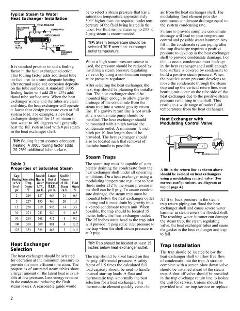
Typical <strong>Steam</strong> to Water<br />
<strong>Heat</strong> Exchanger Installation<br />
It is st<strong>and</strong>ard practice to add a fouling<br />
factor in the heat exchanger selection.<br />
This fouling factor adds additional tube<br />
surface area to assure adequate heating<br />
after normal scale <strong>and</strong> corrosion deposits<br />
on the tube surfaces. A st<strong>and</strong>ard .0005<br />
fouling factor will add 20 to 25% additional<br />
tube surface area. When the heat<br />
exchanger is new <strong>and</strong> the tubes are clean<br />
<strong>and</strong> shiny, the heat exchanger will operate<br />
at lower than design pressure even at full<br />
system load. For example, a new heat<br />
exchanger designed <strong>for</strong> 15 psi steam to<br />
heat water to 160 degrees will generally<br />
heat the full system load with 0 psi steam<br />
in the heat exchanger shell.<br />
Table 1<br />
Properties of Saturated <strong>Steam</strong><br />
<strong>Heat</strong> Exchanger<br />
Selection<br />
The heat exchanger should be selected<br />
<strong>for</strong> operation at the minimum pressure to<br />
provide the most efficient operation. The<br />
properties of saturated steam tables show<br />
a larger amount of the latent heat is available<br />
at low pressure. Less energy remains<br />
in the condensate reducing the flash<br />
steam losses. A reasonable guide would<br />
2<br />
HEATED FLUID<br />
OUTLET<br />
FLUID<br />
TO BE<br />
HEATED<br />
STEAM REGULATOR<br />
STEAM SUPPLY<br />
15 in.<br />
HEAT EXCHANGER<br />
STEAM TRAP<br />
CONDENSATE<br />
OUTLET<br />
TIP: Fouling factor assures adequate<br />
heating. A .0005 fouling factor adds<br />
20-25% additional tube surface.<br />
Gage Sensible Latent Specific<br />
Reading Saturation <strong>Heat</strong> in <strong>Heat</strong> of Volume<br />
at Sea Temp. Water Vaporation of 1 lb. Flash<br />
Level – Degree B.T.U. B.T.U. <strong>Steam</strong> <strong>Steam</strong><br />
psi °F per lb. per lb. cu.ft. %<br />
2 219 187 966 24 0.6<br />
5 227 195 960 20 1.6<br />
15 250 219 945 14 3.9<br />
30 274 243 920 9 6.5<br />
50 298 268 912 8 9.0<br />
100 338 309 881 4 13.2<br />
125 353 325 868 3 14.8<br />
be to select a steam pressure that has a<br />
saturation temperature approximately<br />
30°F higher than the required outlet temperature<br />
of the fluid being heated in the<br />
tubes. For fluid temperatures up to 200°F,<br />
2 psig steam is recommended.<br />
TIP: <strong>Steam</strong> temperature should be<br />
selected 30°F over heat exchanger<br />
outlet temperature.<br />
When a high steam pressure source is<br />
used, the pressure should be reduced by<br />
installing a steam pressure regulating<br />
valve or by using a combination temperature<br />
pressure regulator.<br />
After selecting the heat exchanger, the<br />
next step should be planning the installation.<br />
The heat exchanger should be<br />
mounted high enough to allow gravity<br />
drainage of the condensate from the<br />
steam trap into a vented gravity return<br />
line. If a gravity return line is not available,<br />
a condensate pump should be<br />
installed. The heat exchanger should<br />
be mounted with a pitch toward the<br />
condensate outlet. A minimum 1 /2 inch<br />
pitch per 10 foot length should be<br />
provided. The heat exchanger should<br />
also be located such that removal of<br />
the tube bundle is possible.<br />
<strong>Steam</strong> Traps<br />
The steam trap must be capable of completely<br />
draining the condensate from the<br />
heat exchanger shell under all operating<br />
conditions. On a heat exchanger using a<br />
modulating temperature regulator to heat<br />
fluids under 212°F, the steam pressure in<br />
the shell can be 0 psig. To assure condensate<br />
drainage, the steam trap must be<br />
mounted below the heat exchanger outlet<br />
tapping <strong>and</strong> it must drain by gravity into<br />
a vented condensate return unit. When<br />
possible, the trap should be located 15<br />
inches below the heat exchanger outlet.<br />
The 15 inches static head to the trap inlet<br />
will provide 1 /2 psig static inlet pressure to<br />
the trap when the shell steam pressure is<br />
at 0 psig.<br />
TIP: Trap should be located at least 15<br />
inches below heat exchanger outlet.<br />
The trap should be sized based on this<br />
1 /2 psig differential pressure. A safety<br />
factor of 1.5 times the calculated full<br />
load capacity should be used to h<strong>and</strong>le<br />
unusual start up loads. A float <strong>and</strong><br />
thermostatic trap is normally the best<br />
selection <strong>for</strong> a heat exchanger. The<br />
thermostatic element quickly vents the<br />
air from the heat exchanger shell. The<br />
modulating float element provides<br />
continuous condensate drainage equal to<br />
the system condensing rate.<br />
Failure to provide complete condensate<br />
drainage will lead to poor temperature<br />
control <strong>and</strong> possible water hammer. Any<br />
lift in the condensate return piping after<br />
the trap discharge requires a positive<br />
pressure to develop in the heat exchanger<br />
shell to provide condensate drainage. For<br />
this to occur, condensate must back up<br />
in the heat exchanger shell until enough<br />
tube surface is covered by condensate to<br />
build a positive steam pressure. When<br />
the positive steam pressure develops to<br />
move the condensate through the steam<br />
trap <strong>and</strong> up the vertical return line, over<br />
heating can occur on the tube side of the<br />
heat exchanger due to the positive steam<br />
pressure remaining in the shell. This<br />
results in a wide range of outlet fluid<br />
temperatures from the heat exchanger.<br />
<strong>Heat</strong> Exchanger with<br />
Modulating <strong>Control</strong> Valve<br />
Lift<br />
A lift in the return line as shown above<br />
should be avoided on heat exchangers<br />
using a modulating control valve. (For<br />
correct configurations, see diagram at<br />
top of page 4.)<br />
A lift or back pressure in the steam<br />
trap return piping can flood the heat<br />
exchanger shell <strong>and</strong> cause severe water<br />
hammer as steam enters the flooded shell.<br />
The resulting water hammer can damage<br />
the steam trap, the steam regulating<br />
valve, the heat exchanger tubes <strong>and</strong> cause<br />
the gasket in the heat exchanger <strong>and</strong> trap<br />
to fail.<br />
Trap Installation<br />
The trap should be located below the<br />
heat exchanger shell to allow free flow<br />
of condensate into the trap. A strainer<br />
complete with a screen blow down valve<br />
should be installed ahead of the steam<br />
trap. A shut off valve should be provided<br />
in the trap discharge return line to isolate<br />
the unit <strong>for</strong> service. Unions should be<br />
provided to allow trap service or replace-