Steam Control and Condensate Drainage for Heat ... - UMBC
Steam Control and Condensate Drainage for Heat ... - UMBC
Steam Control and Condensate Drainage for Heat ... - UMBC

You also want an ePaper? Increase the reach of your titles
YUMPU automatically turns print PDFs into web optimized ePapers that Google loves.
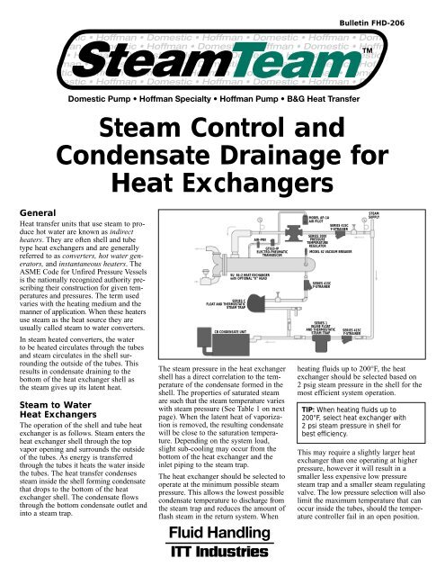
Bulletin FHD-206<br />
<strong>Steam</strong> <strong>Control</strong> <strong>and</strong><br />
<strong>Condensate</strong> <strong>Drainage</strong> <strong>for</strong><br />
<strong>Heat</strong> Exchangers<br />
General<br />
<strong>Heat</strong> transfer units that use steam to produce<br />
hot water are known as indirect<br />
heaters. They are often shell <strong>and</strong> tube<br />
type heat exchangers <strong>and</strong> are generally<br />
referred to as converters, hot water generators,<br />
<strong>and</strong> instantaneous heaters. The<br />
ASME Code <strong>for</strong> Unfired Pressure Vessels<br />
is the nationally recognized authority prescribing<br />
their construction <strong>for</strong> given temperatures<br />
<strong>and</strong> pressures. The term used<br />
varies with the heating medium <strong>and</strong> the<br />
manner of application. When these heaters<br />
use steam as the heat source they are<br />
usually called steam to water converters.<br />
In steam heated converters, the water<br />
to be heated circulates through the tubes<br />
<strong>and</strong> steam circulates in the shell surrounding<br />
the outside of the tubes. This<br />
results in condensate draining to the<br />
bottom of the heat exchanger shell as<br />
the steam gives up its latent heat.<br />
<strong>Steam</strong> to Water<br />
<strong>Heat</strong> Exchangers<br />
The operation of the shell <strong>and</strong> tube heat<br />
exchanger is as follows. <strong>Steam</strong> enters the<br />
heat exchanger shell through the top<br />
vapor opening <strong>and</strong> surrounds the outside<br />
of the tubes. As energy is transferred<br />
through the tubes it heats the water inside<br />
the tubes. The heat transfer condenses<br />
steam inside the shell <strong>for</strong>ming condensate<br />
that drops to the bottom of the heat<br />
exchanger shell. The condensate flows<br />
through the bottom condensate outlet <strong>and</strong><br />
into a steam trap.<br />
SERIES C<br />
FLOAT AND THERMOSTATIC<br />
STEAM TRAP<br />
SU 84-2 HEAT EXCHANGER<br />
with OPTIONAL “K” HEAD<br />
CB CONDENSATE UNIT<br />
AIR-PRV<br />
GT610-IP<br />
ELECTRO-PNEUMATIC<br />
TRANSDUCER<br />
The steam pressure in the heat exchanger<br />
shell has a direct correlation to the temperature<br />
of the condensate <strong>for</strong>med in the<br />
shell. The properties of saturated steam<br />
are such that the steam temperature varies<br />
with steam pressure (See Table 1 on next<br />
page). When the latent heat of vaporization<br />
is removed, the resulting condensate<br />
will be close to the saturation temperature.<br />
Depending on the system load,<br />
slight sub-cooling may occur from the<br />
bottom of the heat exchanger <strong>and</strong> the<br />
inlet piping to the steam trap.<br />
The heat exchanger should be selected to<br />
operate at the minimum possible steam<br />
pressure. This allows the lowest possible<br />
condensate temperature to discharge from<br />
the steam trap <strong>and</strong> reduces the amount of<br />
flash steam in the return system. When<br />
MODEL AP-1A<br />
AIR PILOT<br />
SERIES 415C<br />
Y-STRAINER<br />
SERIES 2000<br />
PRESSURE<br />
TEMPERATURE<br />
REGULATOR<br />
MODEL 62 VACUUM BREAKER<br />
SERIES 415C<br />
Y-STRAINER<br />
SERIES 1<br />
INLINE FLOAT<br />
AND THERMOSTATIC<br />
STEAM TRAP<br />
SERIES 415C<br />
Y-STRAINER<br />
STEAM<br />
SUPPLY<br />
heating fluids up to 200°F, the heat<br />
exchanger should be selected based on<br />
2 psig steam pressure in the shell <strong>for</strong> the<br />
most efficient system operation.<br />
TIP: When heating fluids up to<br />
200°F, select heat exchanger with<br />
2 psi steam pressure in shell <strong>for</strong><br />
best efficiency.<br />
This may require a slightly larger heat<br />
exchanger than one operating at higher<br />
pressure, however it will result in a<br />
smaller less expensive low pressure<br />
steam trap <strong>and</strong> a smaller steam regulating<br />
valve. The low pressure selection will also<br />
limit the maximum temperature that can<br />
occur inside the tubes, should the temperature<br />
controller fail in an open position.
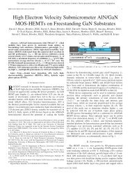
Typical <strong>Steam</strong> to Water<br />
<strong>Heat</strong> Exchanger Installation<br />
It is st<strong>and</strong>ard practice to add a fouling<br />
factor in the heat exchanger selection.<br />
This fouling factor adds additional tube<br />
surface area to assure adequate heating<br />
after normal scale <strong>and</strong> corrosion deposits<br />
on the tube surfaces. A st<strong>and</strong>ard .0005<br />
fouling factor will add 20 to 25% additional<br />
tube surface area. When the heat<br />
exchanger is new <strong>and</strong> the tubes are clean<br />
<strong>and</strong> shiny, the heat exchanger will operate<br />
at lower than design pressure even at full<br />
system load. For example, a new heat<br />
exchanger designed <strong>for</strong> 15 psi steam to<br />
heat water to 160 degrees will generally<br />
heat the full system load with 0 psi steam<br />
in the heat exchanger shell.<br />
Table 1<br />
Properties of Saturated <strong>Steam</strong><br />
<strong>Heat</strong> Exchanger<br />
Selection<br />
The heat exchanger should be selected<br />
<strong>for</strong> operation at the minimum pressure to<br />
provide the most efficient operation. The<br />
properties of saturated steam tables show<br />
a larger amount of the latent heat is available<br />
at low pressure. Less energy remains<br />
in the condensate reducing the flash<br />
steam losses. A reasonable guide would<br />
2<br />
HEATED FLUID<br />
OUTLET<br />
FLUID<br />
TO BE<br />
HEATED<br />
STEAM REGULATOR<br />
STEAM SUPPLY<br />
15 in.<br />
HEAT EXCHANGER<br />
STEAM TRAP<br />
CONDENSATE<br />
OUTLET<br />
TIP: Fouling factor assures adequate<br />
heating. A .0005 fouling factor adds<br />
20-25% additional tube surface.<br />
Gage Sensible Latent Specific<br />
Reading Saturation <strong>Heat</strong> in <strong>Heat</strong> of Volume<br />
at Sea Temp. Water Vaporation of 1 lb. Flash<br />
Level – Degree B.T.U. B.T.U. <strong>Steam</strong> <strong>Steam</strong><br />
psi °F per lb. per lb. cu.ft. %<br />
2 219 187 966 24 0.6<br />
5 227 195 960 20 1.6<br />
15 250 219 945 14 3.9<br />
30 274 243 920 9 6.5<br />
50 298 268 912 8 9.0<br />
100 338 309 881 4 13.2<br />
125 353 325 868 3 14.8<br />
be to select a steam pressure that has a<br />
saturation temperature approximately<br />
30°F higher than the required outlet temperature<br />
of the fluid being heated in the<br />
tubes. For fluid temperatures up to 200°F,<br />
2 psig steam is recommended.<br />
TIP: <strong>Steam</strong> temperature should be<br />
selected 30°F over heat exchanger<br />
outlet temperature.<br />
When a high steam pressure source is<br />
used, the pressure should be reduced by<br />
installing a steam pressure regulating<br />
valve or by using a combination temperature<br />
pressure regulator.<br />
After selecting the heat exchanger, the<br />
next step should be planning the installation.<br />
The heat exchanger should be<br />
mounted high enough to allow gravity<br />
drainage of the condensate from the<br />
steam trap into a vented gravity return<br />
line. If a gravity return line is not available,<br />
a condensate pump should be<br />
installed. The heat exchanger should<br />
be mounted with a pitch toward the<br />
condensate outlet. A minimum 1 /2 inch<br />
pitch per 10 foot length should be<br />
provided. The heat exchanger should<br />
also be located such that removal of<br />
the tube bundle is possible.<br />
<strong>Steam</strong> Traps<br />
The steam trap must be capable of completely<br />
draining the condensate from the<br />
heat exchanger shell under all operating<br />
conditions. On a heat exchanger using a<br />
modulating temperature regulator to heat<br />
fluids under 212°F, the steam pressure in<br />
the shell can be 0 psig. To assure condensate<br />
drainage, the steam trap must be<br />
mounted below the heat exchanger outlet<br />
tapping <strong>and</strong> it must drain by gravity into<br />
a vented condensate return unit. When<br />
possible, the trap should be located 15<br />
inches below the heat exchanger outlet.<br />
The 15 inches static head to the trap inlet<br />
will provide 1 /2 psig static inlet pressure to<br />
the trap when the shell steam pressure is<br />
at 0 psig.<br />
TIP: Trap should be located at least 15<br />
inches below heat exchanger outlet.<br />
The trap should be sized based on this<br />
1 /2 psig differential pressure. A safety<br />
factor of 1.5 times the calculated full<br />
load capacity should be used to h<strong>and</strong>le<br />
unusual start up loads. A float <strong>and</strong><br />
thermostatic trap is normally the best<br />
selection <strong>for</strong> a heat exchanger. The<br />
thermostatic element quickly vents the<br />
air from the heat exchanger shell. The<br />
modulating float element provides<br />
continuous condensate drainage equal to<br />
the system condensing rate.<br />
Failure to provide complete condensate<br />
drainage will lead to poor temperature<br />
control <strong>and</strong> possible water hammer. Any<br />
lift in the condensate return piping after<br />
the trap discharge requires a positive<br />
pressure to develop in the heat exchanger<br />
shell to provide condensate drainage. For<br />
this to occur, condensate must back up<br />
in the heat exchanger shell until enough<br />
tube surface is covered by condensate to<br />
build a positive steam pressure. When<br />
the positive steam pressure develops to<br />
move the condensate through the steam<br />
trap <strong>and</strong> up the vertical return line, over<br />
heating can occur on the tube side of the<br />
heat exchanger due to the positive steam<br />
pressure remaining in the shell. This<br />
results in a wide range of outlet fluid<br />
temperatures from the heat exchanger.<br />
<strong>Heat</strong> Exchanger with<br />
Modulating <strong>Control</strong> Valve<br />
Lift<br />
A lift in the return line as shown above<br />
should be avoided on heat exchangers<br />
using a modulating control valve. (For<br />
correct configurations, see diagram at<br />
top of page 4.)<br />
A lift or back pressure in the steam<br />
trap return piping can flood the heat<br />
exchanger shell <strong>and</strong> cause severe water<br />
hammer as steam enters the flooded shell.<br />
The resulting water hammer can damage<br />
the steam trap, the steam regulating<br />
valve, the heat exchanger tubes <strong>and</strong> cause<br />
the gasket in the heat exchanger <strong>and</strong> trap<br />
to fail.<br />
Trap Installation<br />
The trap should be located below the<br />
heat exchanger shell to allow free flow<br />
of condensate into the trap. A strainer<br />
complete with a screen blow down valve<br />
should be installed ahead of the steam<br />
trap. A shut off valve should be provided<br />
in the trap discharge return line to isolate<br />
the unit <strong>for</strong> service. Unions should be<br />
provided to allow trap service or replace-
ment. The return line from the trap<br />
discharge should be pitched into a<br />
vented condensate return unit.<br />
Vacuum Breakers<br />
Most steam to water heat exchangers<br />
provide a tapping in the shell to allow<br />
installation of a vacuum breaker. The<br />
vacuum breaker allows air to enter the<br />
shell when a induced vacuum occurs.<br />
Failure to install a vacuum breaker will<br />
allow the heat exchanger shell to operate<br />
at a negative pressure which may cause<br />
condensate to be held up in the shell.<br />
During light load, the heat exchanger will<br />
have a layer of steam at the top <strong>and</strong> air<br />
under the steam to provide just the right<br />
amount of heat. The vacuum breaker<br />
should be mounted on a vertical pipe<br />
6 to 10” above the topping to provide<br />
a cooling leg. This will protect the<br />
vacuum breaker from dirt <strong>and</strong> extreme<br />
temperatures.<br />
TIP: Install a vacuum breaker on all<br />
steam converters.<br />
<strong>Steam</strong> Regulator<br />
The choice of the temperature regulating<br />
valve includes self contained temperature<br />
regulators, pilot operated regulators <strong>and</strong><br />
pneumatic regulators.<br />
The steam inlet pressure to the regulator<br />
must be higher than the required heat<br />
exchanger operating pressure to allow<br />
flow. The available steam pressure should<br />
be at least two times the heat exchanger<br />
operating pressure to provide modulation<br />
of the regulator <strong>for</strong> good temperature<br />
control. This will also provide the<br />
smallest size steam regulator.<br />
TIP: For good control, take at least a<br />
50% pressure drop across the control<br />
valve.<br />
The steam regulator should be sized<br />
based on the maximum lb./hr. of steam<br />
required by the heat exchanger. To properly<br />
size the regulator, the available inlet<br />
steam pressure <strong>and</strong> the heat exchanger<br />
design operating pressure must be known.<br />
The steam regulator should not be oversized.<br />
Oversizing the regulator may cause<br />
the temperature to overshoot <strong>and</strong> the<br />
regulator will hunt more than a properly<br />
sized regulator. The steam regulator is<br />
normally smaller than the connecting<br />
inlet <strong>and</strong> outlet steam piping.<br />
Regulator Installation<br />
A steam drip trap should be installed<br />
in the steam piping ahead of all steam<br />
regulating valves. Failure to install<br />
a drip trap will allow condensate to<br />
collect in the steam piping ahead of<br />
the regulator. As the regulator opens,<br />
the mix of condensate <strong>and</strong> steam<br />
passing through the regulator may cause<br />
water hammer that can destroy the<br />
diaphragms or bellows used to operate<br />
the regulator.<br />
A steam strainer should also be installed<br />
ahead of the regulators to prevent dirt<br />
from entering the valve. Dirt can deposit<br />
on the valve seat <strong>and</strong> not allow it to<br />
close tight. The steam strainer should be<br />
installed with the screen pocket horizontally.<br />
Installation with the screen down,<br />
as commonly piped <strong>for</strong> water service,<br />
will allow a condensate pocket to <strong>for</strong>m<br />
in the steam line. This condensate pocket<br />
can carry into the main valve <strong>and</strong> cause<br />
water hammer or sluggish operation.<br />
Shut off valves, pressure gauges, a<br />
manual bypass <strong>and</strong> unions should be<br />
installed to allow proper servicing of the<br />
valves <strong>and</strong> strainers. When possible refer<br />
to the manufacturer’s installation manual<br />
<strong>for</strong> proper installation.<br />
The temperature sensing bulb should be<br />
installed as close as possible to the heat<br />
exchanger outlet. It is important that the<br />
full length of the temperature sensing<br />
bulb be inserted in the system piping.<br />
Any portion of the bulb installed in a<br />
no flow area will reduce the accuracy<br />
of temperature control. When the sensing<br />
bulb is installed in a separable well, heat<br />
transfer compound must be installed<br />
between the well <strong>and</strong> the sensing bulb<br />
to aid heat transfer. The tube side of the<br />
heat exchanger should have a continuous<br />
running recirculation pump to provide<br />
continuous flow past the sensing bulb.<br />
A minimum 20% recirculation should<br />
be provided.<br />
Pilot operated regulators with a pressure<br />
pilot require a downstream pressure<br />
sensing line. The pressure sensing line<br />
connection should be connected in a nonturbulent<br />
area downstream of the main<br />
valve; a minimum 10 pipe diameters<br />
downstream of the main valve is recommended.<br />
The steam pressure sensing<br />
connection can also be connected<br />
directly to the heat exchanger shell.<br />
<strong>Condensate</strong> Coolers<br />
When heat exchangers operate at high<br />
pressure, consideration should be given<br />
to the addition of a condensate cooler.<br />
The justification will be depend on the<br />
size of the heat exchanger <strong>and</strong> the actual<br />
number of hours per day the unit will be<br />
in operation.<br />
With a condensate cooler, the discharge<br />
from the steam trap on the steam heat<br />
exchanger outlet is piped through a waterto-water<br />
heat exchanger. A second trap is<br />
then installed on the discharge of the<br />
water-to-water heat exchanger to maintain<br />
saturation pressure <strong>and</strong> prevent flashing<br />
<strong>and</strong> water hammer from occurring in<br />
the condensate cooler. A separate thermostatic<br />
trap is installed to allow direct air<br />
venting of the steam heat exchanger into<br />
the vented return line downstream of the<br />
condensate cooler.<br />
The water-to-water heat exchanger design<br />
differs from a steam heat exchanger.<br />
The water-to-water heat exchanger has<br />
internal baffles to direct the water flow<br />
across the tubes to improve heat transfer.<br />
Water-to-water heat exchangers are<br />
externally distinguishable as the shell<br />
inlet <strong>and</strong> outlet tappings are the same<br />
size; steam heat exchangers have<br />
a large vapor opening in the top of the<br />
shell <strong>and</strong> a smaller condensate outlet in<br />
the bottom.<br />
The fluid in the condensate cooler<br />
tubes may be the inlet water to the steam<br />
heat exchanger tubes. When the initial<br />
temperature of the fluid is too high to<br />
cool the condensate below 212°F, a<br />
separate fluid may be heated. Preheating<br />
domestic hot water or preheating boiler<br />
make up water are two possibilities.<br />
Installation with<br />
<strong>Condensate</strong> Cooler<br />
TRAP<br />
COOLER<br />
REGULATOR<br />
STEAM SUPPLY<br />
HEAT EXCHANGER<br />
TRAP<br />
THERMOSTATIC<br />
TRAP<br />
COND.<br />
OUTLET<br />
3
<strong>Heat</strong> exchanger installations depending on operating pressures<br />
<strong>and</strong> the of type of return pump.<br />
4<br />
HEAT EXCHANGER<br />
CONDENSATE COOLER<br />
Low Pressure (2 psig or less) with St<strong>and</strong>ard <strong>Condensate</strong> Unit<br />
HEAT EXCHANGER F&T TRAP<br />
HEAT EXCHANGER<br />
STEAM INLET<br />
PUMPED DISCHARGE<br />
THERMOSTATIC<br />
TRAP<br />
STEAM INLET<br />
CONDENSATE<br />
PUMP<br />
CONDENSATE<br />
PUMP<br />
<strong>Heat</strong> exchangers operating at 2 psig or less<br />
can be drained into a st<strong>and</strong>ard low cost<br />
floor mounted condensate returned pump.<br />
High Pressure with Flash Tank <strong>and</strong> Low NPSH <strong>Condensate</strong> Unit<br />
F&T TRAP<br />
STEAM INLET<br />
FLASH TANK<br />
ELEVATED CONDENSATE<br />
UNIT WITH LOW NPSH<br />
PUMP<br />
<strong>Heat</strong> exchangers operating at higher pressure<br />
require a flash tank to vent the flash<br />
steam. An elevated condensate pump unit<br />
equipped with 2-foot NPSH pumps are required<br />
to h<strong>and</strong>le the condensate at saturation<br />
temperature.<br />
High Pressure with <strong>Condensate</strong> Cooler <strong>and</strong> St<strong>and</strong>ard <strong>Condensate</strong> Unit<br />
When it is necessary to operate a heat<br />
exchanger at high pressure (above 15 psig)<br />
a condensate cooler can be added to<br />
sub-cool the condensate below 212°F. The<br />
illustration shows the proper steam trapping<br />
<strong>for</strong> a condensate cooler. The incoming<br />
fluid to the steam heat exchanger may<br />
be used to sub-cool if the temperature is<br />
low enough. A separate cooling source<br />
may also be used.
<strong>Heat</strong> exchanger installations depending on operating pressures<br />
<strong>and</strong> the of type of return pump.<br />
HEAT EXCHANGER<br />
HEAT EXCHANGER<br />
THERMOSTATIC VENT<br />
RESERVOIR<br />
TANK<br />
RESERVOIR TANK<br />
PRESSURE POWERED PUMP<br />
F&T TRAP<br />
Low Pressure <strong>and</strong> Pressure Powered Pump<br />
STEAM SUPPLY<br />
DRIP TRAP<br />
PRESSURE POWERED<br />
PUMP<br />
STEAM SUPPLY<br />
DRIP TRAP<br />
PUMPED DISCHARGE<br />
High Pressure <strong>and</strong> Pressure Powered Pump<br />
STEAM SUPPLY<br />
DRIP TRAP<br />
STEAM SUPPLY<br />
F&T TRAP<br />
TO RETURN LINE<br />
PUMP<br />
DISCHARGE<br />
For additional in<strong>for</strong>mation or assistance in selecting components,<br />
contact your Fluid H<strong>and</strong>ling “<strong>Steam</strong> Team” representative.<br />
A pressure powered pump unit may also be<br />
used to return condensate. The installation<br />
shown would be used on low pressure heat<br />
exchangers. The receiver tank is vented to<br />
atmosphere on this unit.<br />
<strong>Heat</strong> exchangers operating at higher pressures<br />
may use a closed pressure powered<br />
pump system. The installation shown will<br />
allow condensate to discharge directly<br />
through the steam trap when the pressure<br />
on the heat exchanger is higher than the<br />
return line pressure. When the heat<br />
exchanger pressure is not sufficient, the<br />
pressure powered pump receiver will fill<br />
<strong>and</strong> operate to discharge condensate.<br />
The F&T steam trap can be sized based on<br />
the differential pressure from the pressure<br />
powered pump discharge pressure less the<br />
return line back pressure.<br />
5