TL-MR3020 Portable 3G/4G Wireless N Router - TP-Link
TL-MR3020 Portable 3G/4G Wireless N Router - TP-Link
TL-MR3020 Portable 3G/4G Wireless N Router - TP-Link

Create successful ePaper yourself
Turn your PDF publications into a flip-book with our unique Google optimized e-Paper software.
<strong>TL</strong>-<strong>MR3020</strong><strong>Portable</strong> <strong>3G</strong>/<strong>4G</strong> <strong>Wireless</strong> N <strong>Router</strong>Rev: 1.1.01910010551
COPYRIGHT & TRADEMARKSSpecifications are subject to change without notice.is a registered trademark of<strong>TP</strong>-LINK TECHNOLOGIES CO., LTD. Other brands and product names are trademarks orregistered trademarks of their respective holders.No part of the specifications may be reproduced in any form or by any means or used to makeany derivative such as translation, transformation, or adaptation without permission from<strong>TP</strong>-LINK TECHNOLOGIES CO., LTD. Copyright © 2012 <strong>TP</strong>-LINK TECHNOLOGIES CO., LTD.All rights reserved.http://www.tp-link.comI
FCC STATEMENTThis equipment has been tested and found to comply with the limits for a Class B digital device,pursuant to part 15 of the FCC Rules. These limits are designed to provide reasonable protectionagainst harmful interference in a residential installation. This equipment generates, uses and canradiate radio frequency energy and, if not installed and used in accordance with the instructions,may cause harmful interference to radio communications. However, there is no guarantee thatinterference will not occur in a particular installation. If this equipment does cause harmfulinterference to radio or television reception, which can be determined by turning the equipment offand on, the user is encouraged to try to correct the interference by one or more of the followingmeasures:Reorient or relocate the receiving antenna.Increase the separation between the equipment and receiver.Connect the equipment into an outlet on a circuit different from that to which thereceiver is connected.Consult the dealer or an experienced radio/ TV technician for help.This device complies with part 15 of the FCC Rules. Operation is subject to the following twoconditions:1) This device may not cause harmful interference.2) This device must accept any interference received, including interference that may causeundesired operation.Any changes or modifications not expressly approved by the party responsible for compliancecould void the user’s authority to operate the equipment.Note: The manufacturer is not responsible for any radio or tv interference caused byunauthorized modifications to this equipment. Such modifications could void the user’s authorityto operate the equipment.FCC RF Radiation Exposure StatementThis equipment complies with FCC RF radiation exposure limits set forth for an uncontrolledenvironment. This device and its antenna must not be co-located or operating in conjunctionwith any other antenna or transmitter.“To comply with FCC RF exposure compliance requirements, this grant is applicable to onlyMobile Configurations. The antennas used for this transmitter must be installed to provide aseparation distance of at least 20 cm from all persons and must not be co-located or operatingin conjunction with any other antenna or transmitter.”II
CE Mark WarningThis is a class B product. In a domestic environment, this product may cause radio interference,in which case the user may be required to take adequate measures.Canadian Compliance StatementThis device complies with Industry Canada license-exempt RSS standard(s). Operation issubject to the following two conditions:(1)This device may not cause interference, and(2)This device must accept any interference, including interference that may cause undesiredoperation of the device.Cet appareil est conforme aux norms CNR exemptes de licence d’Industrie Canada. Lefonctionnement est soumis aux deux conditions suivantes:(1)cet appareil ne doit pas provoquer d’interférences et(2)cet appareil doit accepter toute interférence, y compris celles susceptibles de provoquer unfonctionnement non souhaité de l’appareil.Industry Canada StatementComplies with the Canadian ICES-003 Class B specifications.Cet appareil numérique de la classe B est conforme à la norme NMB-003 du Canada.This device complies with RSS 210 of Industry Canada. This Class B device meets all therequirements of the Canadian interference-causing equipment regulations.Cet appareil numérique de la Classe B respecte toutes les exigences du Règlement sur lematériel brouilleur du Canada.Korea Warning Statements:당해 무선설비는 운용중 전파혼신 가능성이 있음.NCC Notice:經 型 式 認 證 合 格 之 低 功 率 射 頻 電 機 , 非 經 許 可 , 公 司 、 商 號 或 使 用 者 均 不 得 擅 自 變 更 頻 率 、 加 大功 率 或 變 更 原 設 計 之 特 性 及 功 能 。低 功 率 射 頻 電 機 之 使 用 不 得 影 響 飛 航 安 全 及 干 擾 合 法 通 信 ; 經 發 現 有 干 擾 現 象 時 , 應 立 即 停 用 ,並 改 善 至 無 干 擾 時 方 得 繼 續 使 用 。 前 項 合 法 通 信 , 指 依 電 信 法 規 定 作 業 之 無 線 電 通 信 。 低 功 率 射頻 電 機 須 忍 受 合 法 通 信 或 工 業 、 科 學 及 醫 療 用 電 波 輻 射 性 電 機 設 備 之 干 擾 。III
Продукт сертифіковано згідно с правилами системи УкрСЕПРО на відповідність вимогамнормативних документів та вимогам, що передбачені чинними законодавчими актамиУкраїни.Safety Information• When product has power button, the power button is one of the way to shut off the product;when there is no power button, the only way to completely shut off power is to disconnect theproduct or the power adapter from the power source.• Don’t disassemble the product, or make repairs yourself. You run the risk of electric shockand voiding the limited warranty. If you need service, please contact us.• Avoid water and wet locations.This product can be used in the following countries:AT BG BY CA CZ DE DK EEES FI FR GB GR HU IE I<strong>TL</strong>T LV MT NL NO PL PT RORU SE SK TR UAIV
<strong>TP</strong>-LINK TECHNOLOGIES CO., LTDDECLARATION OF CONFORMITYFor the following equipment:Product Description: <strong>Portable</strong> <strong>3G</strong>/<strong>4G</strong> <strong>Wireless</strong> N <strong>Router</strong>Model No.: <strong>TL</strong>-<strong>MR3020</strong>Trademark: <strong>TP</strong>-LINKWe declare under our own responsibility that the above products satisfy all the technicalregulations applicable to the product within the scope of Council Directives:Directives 1999/5/EC, Directives 2004/108/EC, Directives 2006/95/EC, Directives 1999/519/EC,Directives 2011/65/EUThe above product is in conformity with the following standards or other normative documentsETSI EN 300 328 V1.7.1: 2006ETSI EN 301 489-1 V1.8.1:2008& ETSI EN 301 489-17 V2.1.1:2009EN 55022:2010EN 55024:2010EN 61000-3-2:2006+A1:2009+A2:2009EN 61000-3-3:2008EN60950-1:2006+A11:2009+A1:2010+A12:2011EN62311:2008EN 301 893EN 302 502The product carries the CE Mark:Person is responsible for marking this declaration:Yang HongliangProduct Manager of International BusinessDate of issue: 2012<strong>TP</strong>-LINK TECHNOLOGIES CO., LTD.Building 24 (floors 1, 3, 4, 5), and 28 (floors 1-4) Central Science and Technology Park,Shennan Rd, Nanshan, Shenzhen, China
CONTENTSPackage Contents .......................................................................................................................... 1Chapter 1. Introduction................................................................................................................. 21.1 Overview of the <strong>Router</strong>................................................................................................. 21.2 Conventions ................................................................................................................. 21.3 Main Features .............................................................................................................. 31.4 Panel Layout ................................................................................................................ 41.4.1 The Front Panel................................................................................................ 41.4.2 The Rear Panel ................................................................................................ 5Chapter 2. Connecting the <strong>Router</strong>............................................................................................... 62.1 System Requirements .................................................................................................. 62.2 Installation Environment Requirements........................................................................ 62.3 Connecting the <strong>Router</strong> ................................................................................................. 6Chapter 3. Quick Installation Guide........................................................................................... 103.1 <strong>3G</strong>/<strong>4G</strong> <strong>Router</strong> Mode ................................................................................................... 103.1.1 PC configuration ............................................................................................. 103.1.2 Connect to Network ........................................................................................ 103.1.3 <strong>Router</strong> Configuration....................................................................................... 103.2 WISP Mode ................................................................................................................ 143.2.1 PC configuration ............................................................................................. 143.2.2 Connect to Network ........................................................................................ 143.2.3 <strong>Router</strong> Configuration....................................................................................... 153.3 AP Mode .................................................................................................................... 193.3.1 PC configuration ............................................................................................. 193.3.2 Connect to Network ........................................................................................ 193.3.3 <strong>Router</strong> Configuration....................................................................................... 19Chapter 4. <strong>Router</strong> Configuration-<strong>3G</strong>/<strong>4G</strong> <strong>Router</strong> Mode .............................................................. 274.1 Login .......................................................................................................................... 274.2 Status ......................................................................................................................... 274.3 Quick Setup................................................................................................................ 284.4 WPS ........................................................................................................................... 284.5 Network ...................................................................................................................... 354.5.1 Internet Access ............................................................................................... 354.5.2 <strong>3G</strong>/<strong>4G</strong>............................................................................................................. 374.5.3 WAN ............................................................................................................... 41I
4.5.4 MAC Clone ..................................................................................................... 514.5.5 LAN................................................................................................................. 514.6 <strong>Wireless</strong> ..................................................................................................................... 524.6.1 <strong>Wireless</strong> Settings............................................................................................ 524.6.2 <strong>Wireless</strong> Security............................................................................................ 554.6.3 <strong>Wireless</strong> MAC Filtering ................................................................................... 584.6.4 <strong>Wireless</strong> Advanced ......................................................................................... 604.6.5 <strong>Wireless</strong> Statistics........................................................................................... 614.7 DHCP ......................................................................................................................... 624.7.1 DHCP Settings ............................................................................................... 624.7.2 DHCP Clients List ........................................................................................... 644.7.3 Address Reservation ...................................................................................... 644.8 Forwarding ................................................................................................................. 654.8.1 Virtual Servers ................................................................................................ 664.8.2 Port Triggering ................................................................................................ 674.8.3 DMZ................................................................................................................ 694.8.4 UPnP .............................................................................................................. 704.9 Security ...................................................................................................................... 714.9.1 Basic Security................................................................................................. 714.9.2 Advanced Security.......................................................................................... 724.9.3 Local Management ......................................................................................... 744.9.4 Remote Management ..................................................................................... 754.10 Parental Control ......................................................................................................... 764.11 Access Control ........................................................................................................... 784.11.1 Rule ................................................................................................................ 784.11.2 Host ................................................................................................................ 844.11.3 Target.............................................................................................................. 864.11.4 Schedule......................................................................................................... 884.12 Advanced Routing ...................................................................................................... 894.12.1 Static Routing List........................................................................................... 904.12.2 System Routing Table..................................................................................... 914.13 Bandwidth Control ...................................................................................................... 914.13.1 Control Settings .............................................................................................. 924.13.2 Rules List........................................................................................................ 924.14 IP & MAC Binding....................................................................................................... 934.14.1 Binding Settings.............................................................................................. 934.14.2 ARP List.......................................................................................................... 95II
4.15 Dynamic DNS............................................................................................................. 964.15.1 Comexe.cn DDNS .......................................................................................... 964.15.2 Dyndns.org DDNS .......................................................................................... 974.15.3 No-ip.com DDNS ............................................................................................ 984.16 System Tools.............................................................................................................. 994.16.1 Time Settings................................................................................................ 1004.16.2 Diagnostic..................................................................................................... 1014.16.3 Firmware Upgrade........................................................................................ 1034.16.4 Factory Defaults ........................................................................................... 1044.16.5 Backup & Restore......................................................................................... 1044.16.6 Reboot.......................................................................................................... 1054.16.7 Password...................................................................................................... 1064.16.8 System Log................................................................................................... 1064.16.9 Working Mode .............................................................................................. 1074.16.10 Statistics.................................................................................................... 108Chapter 5. <strong>Router</strong> Configuration—WISP Mode .......................................................................1105.1 Login .........................................................................................................................1105.2 Status ........................................................................................................................1105.3 Quick Setup...............................................................................................................1115.4 WPS ..........................................................................................................................1115.5 Network .....................................................................................................................1185.5.1 WAN ..............................................................................................................1185.5.2 MAC Clone ................................................................................................... 1285.5.3 LAN............................................................................................................... 1285.6 <strong>Wireless</strong> ................................................................................................................... 1295.6.1 <strong>Wireless</strong> Settings.......................................................................................... 1295.6.2 <strong>Wireless</strong> Security.......................................................................................... 1325.6.3 <strong>Wireless</strong> MAC Filtering ................................................................................. 1355.6.4 <strong>Wireless</strong> Advanced ....................................................................................... 1385.6.5 <strong>Wireless</strong> Statistics......................................................................................... 1395.7 DHCP ....................................................................................................................... 1405.7.1 DHCP Settings ............................................................................................. 1405.7.2 DHCP Clients List ......................................................................................... 1415.7.3 Address Reservation .................................................................................... 1425.8 Forwarding ............................................................................................................... 1435.8.1 Virtual Servers .............................................................................................. 1435.8.2 Port Triggering .............................................................................................. 145III
5.8.3 DMZ.............................................................................................................. 1475.8.4 UPnP ............................................................................................................ 1485.9 Security .................................................................................................................... 1495.9.1 Basic Security............................................................................................... 1495.9.2 Advanced Security........................................................................................ 1505.9.3 Local Management ....................................................................................... 1525.9.4 Remote Management ................................................................................... 1535.10 Parental Control ....................................................................................................... 1545.11 Access Control ......................................................................................................... 1575.11.1 Rule .............................................................................................................. 1575.11.2 Host .............................................................................................................. 1625.11.3 Target............................................................................................................ 1645.11.4 Schedule....................................................................................................... 1665.12 Advanced Routing.................................................................................................... 1675.12.1 Static Routing List......................................................................................... 1685.12.2 System Routing Table................................................................................... 1695.13 Bandwidth Control .................................................................................................... 1695.13.1 Control Settings ............................................................................................ 1705.13.2 Rules List...................................................................................................... 1705.14 IP & MAC Binding Setting ........................................................................................ 1715.14.1 Binding Settings............................................................................................ 1715.14.2 ARP List........................................................................................................ 1735.15 Dynamic DNS........................................................................................................... 1745.15.1 Comexe.cn DDNS ........................................................................................ 1745.15.2 Dyndns.org DDNS ........................................................................................ 1755.15.3 No-ip.com DDNS .......................................................................................... 1765.16 System Tools............................................................................................................ 1775.16.1 Time Setting.................................................................................................. 1785.16.2 Diagnostic..................................................................................................... 1795.16.3 Firmware Upgrade........................................................................................ 1815.16.4 Factory Defaults ........................................................................................... 1825.16.5 Backup & Restore......................................................................................... 1825.16.6 Reboot.......................................................................................................... 1835.16.7 Password...................................................................................................... 1845.16.8 System Log................................................................................................... 1845.16.9 Working Mode .............................................................................................. 1855.16.10 Statistics.................................................................................................... 186IV
Chapter 6. <strong>Router</strong> Configuration—AP Mode........................................................................... 1886.1 Login ........................................................................................................................ 1886.2 Status ....................................................................................................................... 1886.3 Quick Setup.............................................................................................................. 1906.4 WPS ......................................................................................................................... 1906.5 Network .................................................................................................................... 1976.6 <strong>Wireless</strong> ................................................................................................................... 1986.6.1 <strong>Wireless</strong> Settings.......................................................................................... 1996.6.2 <strong>Wireless</strong> Security.......................................................................................... 2066.6.3 <strong>Wireless</strong> MAC Filtering ................................................................................. 2146.6.4 <strong>Wireless</strong> Advanced ....................................................................................... 2176.6.5 <strong>Wireless</strong> Statistics......................................................................................... 2186.7 DHCP ....................................................................................................................... 2186.7.1 DHCP Settings ............................................................................................. 2196.7.2 DHCP Clients List ......................................................................................... 2206.7.3 Address Reservation .................................................................................... 2216.8 System Tools............................................................................................................ 2226.8.1 Time Setting.................................................................................................. 2226.8.2 Diagnostic..................................................................................................... 2246.8.3 Firmware Upgrade........................................................................................ 2266.8.4 Factory Defaults ........................................................................................... 2276.8.5 Backup & Restore......................................................................................... 2276.8.6 Reboot.......................................................................................................... 2286.8.7 Password...................................................................................................... 2296.8.8 System Log................................................................................................... 2296.8.9 Working Mode .............................................................................................. 2306.8.10 Statistics ....................................................................................................... 231Appendix A: FAQ........................................................................................................................ 233Appendix B: Configuring the PCs............................................................................................. 239Appendix C: Specifications....................................................................................................... 243Appendix D: Glossary................................................................................................................ 244Appendix E: Compatible <strong>3G</strong>/<strong>4G</strong> USB Modem .......................................................................... 246V
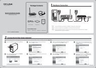
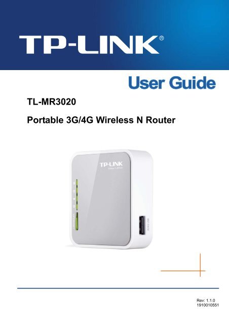
<strong>TL</strong>-<strong>MR3020</strong><strong>Portable</strong> <strong>3G</strong>/<strong>4G</strong> <strong>Wireless</strong> N <strong>Router</strong>Package ContentsThe following items should be found in your package:‣ <strong>Portable</strong> <strong>3G</strong>/<strong>4G</strong> <strong>Wireless</strong> N <strong>Router</strong> <strong>TL</strong>-<strong>MR3020</strong>‣ Power Adapter for <strong>Portable</strong> <strong>3G</strong>/<strong>4G</strong> <strong>Wireless</strong> N <strong>Router</strong> <strong>TL</strong>-<strong>MR3020</strong>‣ USB Cable‣ Ethernet cable‣ Quick Installation Guide‣ Resource CD for <strong>Portable</strong> <strong>3G</strong>/<strong>4G</strong> <strong>Wireless</strong> N <strong>Router</strong> <strong>TL</strong>-<strong>MR3020</strong>, including:This GuideOther Helpful Information Note:Make sure that the package contains the above items. If any of the listed items are damaged ormissing, please contact your distributor.-1-
<strong>TL</strong>-<strong>MR3020</strong><strong>Portable</strong> <strong>3G</strong>/<strong>4G</strong> <strong>Wireless</strong> N <strong>Router</strong>Chapter 1. Introduction1.1 Overview of the <strong>Router</strong><strong>TP</strong>-LINK understands the need for sharing the <strong>3G</strong>/<strong>4G</strong> connection on the go and so we’verealized the convenience with our latest <strong>Portable</strong> <strong>Wireless</strong> N <strong>3G</strong>/<strong>4G</strong> <strong>Router</strong> <strong>TL</strong>-<strong>MR3020</strong> ----- itgives you the freedom to quickly set up a stable and high speed wireless network, up to150Mbps, on-the-go and share a <strong>3G</strong>/<strong>4G</strong> connection. By connecting a <strong>3G</strong>/<strong>4G</strong> USB Card to therouter, a Wi-Fi hotspot is instantly established allowing users to share a Internet connectionanywhere <strong>3G</strong>/<strong>4G</strong> coverage is available. So whether you’re on the train, camping, or at aconstruction site, you’ll have a reliable wireless connection to accommodate your networkingneeds.Flexible Network ConnectionThe <strong>Portable</strong> <strong>3G</strong>/<strong>4G</strong> <strong>Wireless</strong> N <strong>Router</strong> <strong>TL</strong>-<strong>MR3020</strong> provides <strong>3G</strong>/<strong>4G</strong> <strong>Router</strong>, WISP Client<strong>Router</strong> and Access Point modes for network connection, providing the best flexibility. The<strong>Router</strong> supports <strong>3G</strong>/<strong>4G</strong> and WAN (PPPoE, Dynamic IP, Static IP, PP<strong>TP</strong>, L2<strong>TP</strong> Cable)broadband connections for Internet access. You can visit the Internet no matter at home oroutside on business.Excellent CompatibilityThe <strong>Portable</strong> <strong>3G</strong>/<strong>4G</strong> <strong>Wireless</strong> N <strong>Router</strong> <strong>TL</strong>-<strong>MR3020</strong> is compatible with iPad, iTouch, AndroidPhone, Kindle and majority portable WiFi devices. With a standard USB 2.0 port for <strong>3G</strong>/<strong>4G</strong>Modem, the <strong>Router</strong> is compatible with LTE/HSPA+/HSUPA/HSDPA/UMTS/EVDO USB <strong>3G</strong>/<strong>4G</strong>modems.Incredibly High Speed<strong>TP</strong>-LINK <strong>3G</strong>/<strong>4G</strong> wireless N <strong>Router</strong> provides up to 150Mbps, faster than that of traditional 11gproducts, surpasses 11g performance enabling the use of high bandwidth-consumingapplications such as HD Videos. It provides 150Mbps wireless connectivity for the networkshare on the go.Low Power ConsumptionWith a Mini USB port, the <strong>Router</strong> can be powered by laptop or Power Adapter with Low Powerconsumption.1.2 ConventionsThe <strong>Router</strong> or <strong>TL</strong>-<strong>MR3020</strong> mentioned in this guide stands for <strong>Portable</strong> <strong>3G</strong>/<strong>4G</strong> <strong>Wireless</strong> N<strong>Router</strong> <strong>TL</strong>-<strong>MR3020</strong> without any explanation.-2-
<strong>TL</strong>-<strong>MR3020</strong><strong>Portable</strong> <strong>3G</strong>/<strong>4G</strong> <strong>Wireless</strong> N <strong>Router</strong>1.3 Main Features‣ Travel size design, small enough to take on the road‣ One 10/100M Auto-Negotiation RJ45 Ethernet port, one USB 2.0 Port,one mini USB port‣ Compatible with IEEE 802.11n/g/b, IEEE802.3/3u‣ Compatible with LTE/HSPA+/HSUPA/HSDPA/UMTS/EVDO USB <strong>3G</strong>/<strong>4G</strong> Modem‣ Compatible with iPad, iTouch, Android Phone, Kindle and majority portable WiFi devices‣ <strong>Wireless</strong> Lite N speed up to 150Mbps‣ Supports WPS one button security setup‣ Provides WEP, WPA/WPA2, WPA-PSK/WPA2-PSK authentication, TKIP/AES encryptionsecurity‣ Powered by laptop or Power Adapter with Low Power Consumption‣ Supports <strong>3G</strong>/<strong>4G</strong> <strong>Router</strong> Mode, WISP Client <strong>Router</strong> Mode, and AP Mode‣ Supports <strong>3G</strong>/<strong>4G</strong>/PPPoE/Dynamic IP/Static IP/PP<strong>TP</strong>/L2<strong>TP</strong> Cable Internet access‣ Supports VPN Pass-through, Virtual Server and DMZ Host‣ Supports UPnP, Dynamic DNS, Static Routing‣ Provides Automatic-connection and Scheduled Connection on certain time to the Internet‣ Built-in NAT and DHCP server supporting automatic and dynamic IP address IP addressdistribution‣ Connects Internet on demand and disconnects from the Internet when idle for PPPoE‣ Provides 64/128/152-bit WEP encryption security and wireless LAN ACL (Access ControlList)‣ Supports Flow Statistics‣ Supports firmware upgrade and Web management-3-
<strong>TL</strong>-<strong>MR3020</strong><strong>Portable</strong> <strong>3G</strong>/<strong>4G</strong> <strong>Wireless</strong> N <strong>Router</strong>1.4 Panel Layout1.4.1 The Front PanelFigure 1-1 Front Panel sketchThe <strong>Router</strong>’s LEDs are located on the front panel (View from top to bottom).Name Status IndicationPowerInternetWLANRJ45EthernetOnOffOnFlashingOffOnFlashingOffOnFlashingOffPower is on.Power is off.The router is connected to the Internet, but there is no data beingtransferred.The router is transferring data.The router is not connected to the Internet.The <strong>Wireless</strong> function is enabled.There is data being transferred through wireless.The <strong>Wireless</strong> function is disabled.A device is linked to the corresponding port but there is no activity.The Ethernet port is transferring data.No device is linked to the corresponding port.Table 1-1 The LEDs description‣ WPS/RESET: To use WPS function, please push the button for less than 5 seconds, andthen the WPS LED will flash; to reset the router, please push the button for atleast 10 seconds.-4-
<strong>TL</strong>-<strong>MR3020</strong><strong>Portable</strong> <strong>3G</strong>/<strong>4G</strong> <strong>Wireless</strong> N <strong>Router</strong>1.4.2 The Rear PanelFigure 1-2 Rear Panel sketchThe following parts are located on the rear panel (View from left to right).‣ <strong>3G</strong>/<strong>4G</strong> USB Port: This port is used to plug a <strong>3G</strong>/<strong>4G</strong> modem/card.‣ Mini USB Port: This port is used to connect the provided power adapter.‣ RJ45 Ethernet Port: This port can be LAN or WAN port depending on the working mode.‣ Mode Switch: This button is used to switch the working mode of the router.-5-
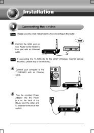
<strong>TL</strong>-<strong>MR3020</strong><strong>Portable</strong> <strong>3G</strong>/<strong>4G</strong> <strong>Wireless</strong> N <strong>Router</strong>Chapter 2. Connecting the <strong>Router</strong>2.1 System Requirements‣ <strong>3G</strong>/<strong>4G</strong> Mobile Broadband Internet Access Service (With a LTE /HSPA+ /HSUPA /HSDPA/UMTS /EVDO USB dongle)‣ PCs with a working Ethernet Adapter and an Ethernet cable with RJ45 connectors‣ TCP/IP protocol on each PC‣ Web browser, such as Microsoft Internet Explorer 5.0 , Netscape Navigator 6.0 or above2.2 Installation Environment Requirements‣ Place the <strong>Router</strong> in a well ventilated place far from any heater or heating vent‣ Avoid direct irradiation of any strong light (such as sunlight)‣ Keep at least 2 inches (5 cm) of clear space around the <strong>Router</strong>‣ Operating Temperature: 0 ℃ ~40 ℃ (32 ℃ ~104 ℃ )‣ Operating Humidity: 10%~90%RH, Non-condensing2.3 Connecting the <strong>Router</strong>The <strong>Router</strong> supports three modes, <strong>3G</strong>/<strong>4G</strong> router mode, WISP mode and AP mode. You candeploy the mode appropriate to your actual network environment. To connect the <strong>Router</strong>, pleasetake the following steps for different modes.a. <strong>3G</strong>/<strong>4G</strong> <strong>Router</strong> ModeIn <strong>3G</strong>/<strong>4G</strong> router mode, with a <strong>3G</strong>/<strong>4G</strong> modem/card, this <strong>Router</strong> can join a <strong>3G</strong>/<strong>4G</strong> network as wellas act as a wireless central hub to broadcast its SSID. Thus, the other wireless devices canconnect to the <strong>Router</strong> so as to join the same <strong>3G</strong>/<strong>4G</strong> network.-6-
<strong>TL</strong>-<strong>MR3020</strong><strong>Portable</strong> <strong>3G</strong>/<strong>4G</strong> <strong>Wireless</strong> N <strong>Router</strong>1. Switch the mode of the <strong>Router</strong> on <strong>3G</strong>/<strong>4G</strong> <strong>Router</strong> mode.2. Connect the notebook/PC to the Ethernet port of <strong>TL</strong>-<strong>MR3020</strong> <strong>Router</strong> with an Ethernetcable.3. Connect the <strong>3G</strong>/<strong>4G</strong> modem/card to the <strong>3G</strong>/<strong>4G</strong> USB port of the <strong>Router</strong>.4. Connect one end of the provided USB cable to mini USB port of the <strong>Router</strong> and the otherend to the power adapter, and then plug the power adapter to a standard electrical wallsocket.b. WISP ModeIn WISP mode, the <strong>Router</strong> will act as a wireless card to connect with WISP as well as a wirelesscentral hub to broadcast its SSID for your wireless LAN clients, and the other wireless devicescan connect to the <strong>Router</strong> for Internet connection.1. Switch the mode of the <strong>Router</strong> on WISP mode.2. Connect the notebook/PC to the Ethernet port of <strong>TL</strong>-<strong>MR3020</strong> <strong>Router</strong> with an Ethernetcable.3. Connect one end of the provided USB cable to mini USB port of the <strong>Router</strong> and the otherend to the power adapter, and then plug the power adapter to a standard electrical wallsocket.-7-
<strong>TL</strong>-<strong>MR3020</strong><strong>Portable</strong> <strong>3G</strong>/<strong>4G</strong> <strong>Wireless</strong> N <strong>Router</strong>c. AP ModeIn AP mode, the <strong>Router</strong> will act as a wireless access point supporting four modes, Access Pointmode, Repeater mode, Bridge with AP mode and Client mode. Please connect the <strong>Router</strong>according to your desired mode.a) Access Point ModeIn this mode, the <strong>Router</strong> will act as a wireless central hub for your wireless LAN clients, giving awireless extension for your current wired network.b) Repeater ModeIn this mode, the <strong>Router</strong> can extend the coverage of another wireless Access Point or <strong>Router</strong>.c) Bridge with AP ModeIn this mode, the <strong>Router</strong> can wirelessly connect two remote LANs together.-8-
<strong>TL</strong>-<strong>MR3020</strong><strong>Portable</strong> <strong>3G</strong>/<strong>4G</strong> <strong>Wireless</strong> N <strong>Router</strong>d) Client ModeIn this mode, the <strong>Router</strong> will act as a wireless card to connect with wireless network.-9-
<strong>TL</strong>-<strong>MR3020</strong><strong>Portable</strong> <strong>3G</strong>/<strong>4G</strong> <strong>Wireless</strong> N <strong>Router</strong>Chapter 3. Quick Installation GuideThis chapter will show you how to configure the basic functions of your <strong>Portable</strong> <strong>3G</strong>/<strong>4G</strong><strong>Wireless</strong> N <strong>Router</strong> using Quick Setup Wizard within minutes.3.1 <strong>3G</strong>/<strong>4G</strong> <strong>Router</strong> ModeThe default IP address of the <strong>Portable</strong> <strong>3G</strong>/<strong>4G</strong> <strong>Wireless</strong> N <strong>Router</strong> is 192.168.0.254 and thedefault Subnet Mask is 255.255.255.0. These values can be changed as you desire. In thisguide, we all use the default values for description.3.1.1 PC configurationHere we take <strong>Wireless</strong> Network Connection as an example. (You can also go to Local AreaConnection to configure the PC for wired network connection, and then configure the router. Ifyou need instructions as to how to do this, please refer to Appendix B: "Configuring the PC.")1. For Windows XP, please go to Start → Settings → Control Panel → Network andInternet Connections → Network Connections; for Windows 7, please go to Start →Settings → Control Panel → View network status and tasks → Manage networkconnection. Right click <strong>Wireless</strong> Network Connection, and select Properties.2. For Windows XP, double click Internet Protocol (TCP/IP) in the item list; for Windows 7,double click Internet Protocol Version 4 (TCP/IPv4).3. Select “Obtain an IP address automatically” and “Obtain DNS server addressautomatically”. Click OK to finish the settings.3.1.2 Connect to Network1. Click the icon at the bottom of your desktop.2. Click “Refresh network list”, and then select the network. Click Connect. Note:The default SSID of the network is <strong>TP</strong>-LINK_POCKET_3020_xxxxxx. (The xxxxxx is the last sixcharacters of the router’s MAC address.)3. When Connected appears, you’ve successfully connected to the wireless network.3.1.3 <strong>Router</strong> Configuration1. To access the configuration utility, open a web-browser and type the default addresshttp://192.168.0.254 in the address field of the browser.Figure 3-1 Login the <strong>Router</strong>-10-
<strong>TL</strong>-<strong>MR3020</strong><strong>Portable</strong> <strong>3G</strong>/<strong>4G</strong> <strong>Wireless</strong> N <strong>Router</strong>2. After a moment, a login window will appear, similar to the Figure 3-2. Enter admin for theUser Name and Password, both in lower case letters. Then click the OK button or press theEnter key.Figure 3-2 Login Windows Note:If the above screen does not pop-up, it means that your Web-browser has been set to a proxy.Go to Tools menu>Internet Options>Connections>LAN Settings, in the screen that appears,cancel the Using Proxy checkbox, and click OK to finish it.3. Go to Status and check the <strong>3G</strong>/<strong>4G</strong> status. When the <strong>3G</strong>/<strong>4G</strong> USB Modem is identified, goto the next step.4. Go to Quick Setup and click Next.Figure 3-3 Status – <strong>3G</strong>/<strong>4G</strong>-11-
<strong>TL</strong>-<strong>MR3020</strong><strong>Portable</strong> <strong>3G</strong>/<strong>4G</strong> <strong>Wireless</strong> N <strong>Router</strong>Figure 3-4 Quick Setup5. Choose the Internet Access type, and then click Next. Here we take <strong>3G</strong>/<strong>4G</strong> Only forexample.Figure 3-5 Quick Setup – Internet Access‣ <strong>3G</strong>/<strong>4G</strong> Only (Recommended) - Only use <strong>3G</strong>/<strong>4G</strong> as the access to the Internet. TheEthernet port is used as LAN port.‣ <strong>3G</strong>/<strong>4G</strong> Preferred - Use <strong>3G</strong>/<strong>4G</strong> as the primary access, WAN as a backup. TheEthernet port is used as WAN port.‣ WAN Preferred - Use WAN as the primary access, <strong>3G</strong>/<strong>4G</strong> as a backup. The Ethernetport is used as WAN port.‣ WAN Only - Only use WAN as the access to the Internet. The Ethernet port is usedas WAN port.6. Select your location and Mobile ISP. You can tick “Set the Dial Number, APN, Usernameand Password manually” to manually set them according to the information your <strong>3G</strong>/<strong>4G</strong>ISP provided. Then click Next.-12-
<strong>TL</strong>-<strong>MR3020</strong><strong>Portable</strong> <strong>3G</strong>/<strong>4G</strong> <strong>Wireless</strong> N <strong>Router</strong>Figure 3-6 Quick Setup – <strong>3G</strong>/<strong>4G</strong>7. Set your wireless parameters. It’s recommended that you edit the following two items, andthen click Next.1) Create a unique and easy-to-remember <strong>Wireless</strong> Network Name.2) Select WPA-Personal/WPA2-Personal under <strong>Wireless</strong> Security and enter apassword in the field.Figure 3-7 Quick Setup – <strong>Wireless</strong>8. Click Reboot to make the settings take effect.-13-
<strong>TL</strong>-<strong>MR3020</strong><strong>Portable</strong> <strong>3G</strong>/<strong>4G</strong> <strong>Wireless</strong> N <strong>Router</strong>Figure 3-8 Quick Setup – Finish Note:After the rebooting, please reconnect to the network according to 3.1.2 Connect to Network. If<strong>Wireless</strong> Security is enabled, you need to enter the password you’ve just set to successfullyfinish the connecting.3.2 WISP ModeThe default IP address of the <strong>Portable</strong> <strong>3G</strong>/<strong>4G</strong> <strong>Wireless</strong> N <strong>Router</strong> is 192.168.0.254 and thedefault Subnet Mask is 255.255.255.0. These values can be changed as you desire. In thisguide, we all use the default values for description.3.2.1 PC configurationHere we take <strong>Wireless</strong> Network Connection as an example. (You can also go to Local AreaConnection to configure the PC for wired network connection, and then configure the router. Ifyou need instructions as to how to do this, please refer to Appendix B: "Configuring the PC.")1. For Windows XP, please go to Start → Settings → Control Panel → Network andInternet Connections → Network Connections; for Windows 7, please go to Start →Settings → Control Panel → View network status and tasks → Manage networkconnection. Right click <strong>Wireless</strong> Network Connection, and select Properties.2. For Windows XP, double click Internet Protocol (TCP/IP) in the item list; for Windows 7,double click Internet Protocol Version 4 (TCP/IPv4).3. Select “Obtain an IP address automatically” and “Obtain DNS server addressautomatically”. Click OK to finish the settings.3.2.2 Connect to Network1. Click the icon at the bottom of your desktop.2. Click “Refresh network list”, and then select the network. Click Connect. Note:The default SSID of the network is <strong>TP</strong>-LINK_POCKET_3020_xxxxxx. (The xxxxxx is the last sixcharacters of the router’s MAC address.)-14-
<strong>TL</strong>-<strong>MR3020</strong><strong>Portable</strong> <strong>3G</strong>/<strong>4G</strong> <strong>Wireless</strong> N <strong>Router</strong>3. When Connected appears, you’ve successfully connected to the wireless network.3.2.3 <strong>Router</strong> Configuration1. To access the configuration utility, open a web-browser and type the default addresshttp://192.168.0.254 in the address field of the browser.Figure 3-9 Login the <strong>Router</strong>2. After a moment, a login window will appear, similar to the Figure 3-10. Enter admin for theUser Name and Password, both in lower case letters. Then click the OK button or press theEnter key.Figure 3-10 Login Windows Note:If the above screen does not pop-up, it means that your Web-browser has been set to a proxy.Go to Tools menu>Internet Options>Connections>LAN Settings, in the screen that appears,cancel the Using Proxy checkbox, and click OK to finish it.3. Go to Quick Setup and click Next.Figure 3-11 Quick Setup-15-
<strong>TL</strong>-<strong>MR3020</strong><strong>Portable</strong> <strong>3G</strong>/<strong>4G</strong> <strong>Wireless</strong> N <strong>Router</strong>4. Choose your WAN Connection type and click Next to continue.Figure 3-12 Quick Setup – WAN Connection Type‣ If the connection type is PPPoE, the next screen will appear as shown in Figure 3-13.Figure 3-13 Quick Setup – PPPoE• User Name and Password - Enter the User Name and Password provided byyour ISP. These fields are case sensitive. If you have difficulty with this process,please contact your ISP.• Confirm Password - Re-enter the password provided by your ISP to ensure thePassword you entered is correct. If the Password is different from the ConfirmPassword, the screen will appear as shown below. Click OK, and re-enter thePassword and Confirm Password.‣ If the connection type is Dynamic IP, the next screen will appear as shown in Figure3-14.-16-
<strong>TL</strong>-<strong>MR3020</strong><strong>Portable</strong> <strong>3G</strong>/<strong>4G</strong> <strong>Wireless</strong> N <strong>Router</strong>Figure 3-14 Quick Setup – MAC Clone• If you are visiting the <strong>Router</strong> from the main computer, please select Yes, and thenclick Clone MAC Address.• If you are visiting the <strong>Router</strong> from another computer, rather than the maincomputer, please select No, and then enter the main computer’s MAC in the fieldWAN MAC Address.Figure 3-15 Quick Setup – MAC Clone‣ If the connection type detected is Static IP, the next screen will appear as shown inFigure 3-16.Figure 3-16 Quick Setup - Static IP-17-
<strong>TL</strong>-<strong>MR3020</strong><strong>Portable</strong> <strong>3G</strong>/<strong>4G</strong> <strong>Wireless</strong> N <strong>Router</strong>• IP Address - This is the WAN IP address seen by external users on the Internet(including your ISP). Enter the IP address into the field.• Subnet Mask - The Subnet Mask is used for the WAN IP address, it is usually255.255.255.0.• Default Gateway - Enter the gateway IP address into the box if required.• Primary DNS - Enter the DNS Server IP address into the box if required.• Secondary DNS - If your ISP provides another DNS server, enter it into this field.5. Click Next to continue, the <strong>Wireless</strong> settings page will appear as shown in Figure 3-17.Click Survey button to find the available wireless networks. Select the SSID of your targetnetwork and click Connect, and the SSID and BSSID will be filled automatically. If thenetwork security is on, please select the Key type and enter the Password.Figure 3-17 Quick Setup – <strong>Wireless</strong>6. Click Next and you will see the page as shown in Figure 3-18. Click the Reboot button tomake your wireless configuration take effect and finish the Quick Setup. (You’rerecommended to go to <strong>Wireless</strong> > <strong>Wireless</strong> Security to set up the wireless security.)Figure 3-18 Quick Setup – Finish-18-
<strong>TL</strong>-<strong>MR3020</strong><strong>Portable</strong> <strong>3G</strong>/<strong>4G</strong> <strong>Wireless</strong> N <strong>Router</strong> Note:After the rebooting, please reconnect to the network according to 3.2.2 Connect to Network. If<strong>Wireless</strong> Security is enabled, you need to enter the password you’ve just set to successfullyfinish the connecting.3.3 AP Mode3.3.1 PC configurationHere we take <strong>Wireless</strong> Network Connection as an example. (You can also go to Local AreaConnection to configure the PC for wired network connection, and then configure the router. Ifyou need instructions as to how to do this, please refer to Appendix B: "Configuring the PC.")1. For Windows XP, please go to Start → Settings → Control Panel → Network andInternet Connections → Network Connections; for Windows 7, please go to Start →Settings → Control Panel → View network status and tasks → Manage networkconnection. Right click <strong>Wireless</strong> Network Connection, and select Properties.2. For Windows XP, double click Internet Protocol (TCP/IP) in the item list; for Windows 7,double click Internet Protocol Version 4 (TCP/IPv4).3. Select “Use the following IP address”, enter the 192.168.0.x as the IP address (x can beany number from 1 to 253), 255.255.255.0 as the Subnet mask; select “Use the followingDNS server addresses”, enter the DNS server address provided by your ISP or networkadministrator.4. Click OK to finish the settings.3.3.2 Connect to Network1. Click the icon at the bottom of your desktop.2. Click “Refresh network list”, and then select the network. Click Connect. Note:The default SSID of the network is <strong>TP</strong>-LINK_POCKET_3020_xxxxxx. (The xxxxxx is the last sixcharacters of the router’s MAC address.)3. When Connected appears, you’ve successfully connected to the wireless network.3.3.3 <strong>Router</strong> Configuration1. To access the configuration utility, open a web-browser and type the default addresshttp://192.168.0.254 in the address field of the browser.Figure 3-19 Login the <strong>Router</strong>-19-
<strong>TL</strong>-<strong>MR3020</strong><strong>Portable</strong> <strong>3G</strong>/<strong>4G</strong> <strong>Wireless</strong> N <strong>Router</strong>2. After a moment, a login window will appear, similar to the Figure 3-20. Enter admin for theUser Name and Password, both in lower case letters. Then click the OK button or press theEnter key.Figure 3-20 Login Windows Note:If the above screen does not pop-up, it means that your Web-browser has been set to a proxy.Go to Tools menu>Internet Options>Connections>LAN Settings, in the screen that appears,cancel the Using Proxy checkbox, and click OK to finish it.3. Go to Quick Setup and click Next.Figure 3-21 Quick Setup4. Choose the <strong>Wireless</strong> Operation Mode Type and click Next.-20-
<strong>TL</strong>-<strong>MR3020</strong><strong>Portable</strong> <strong>3G</strong>/<strong>4G</strong> <strong>Wireless</strong> N <strong>Router</strong>Figure 3-22 Quick Setup – <strong>Wireless</strong> Operation Mode‣ If you choose Access Point (AP), the next screen will appear as shown in Figure 3-23.This operation mode allows wireless stations to access.Figure 3-23 Quick Setup – AP• <strong>Wireless</strong> Network Name (SSID) - Enter a string of up to 32 characters. Thesame Name (SSID) must be assigned to all wireless devices in your network. Thedefault SSID is set to be <strong>TP</strong>-LINK_POCKET_xxxxxx (xxxxxx indicates the lastunique six characters of each <strong>Router</strong>'s MAC address), which can ensure yourwireless network security. But it is recommended strongly that you change yournetworks name (SSID) to a different value. This value is case-sensitive. Forexample, MYSSID is NOT the same as MySsid.-21-
<strong>TL</strong>-<strong>MR3020</strong><strong>Portable</strong> <strong>3G</strong>/<strong>4G</strong> <strong>Wireless</strong> N <strong>Router</strong>• Region - Select your region from the pull-down list. This field specifies the regionwhere the wireless function of the <strong>Router</strong> can be used. It may be illegal to use thewireless function of the <strong>Router</strong> in a region other than one of those specified in thisfiled. If your country or region is not listed, please contact your local governmentagency for assistance.• Channel - This field determines which operating frequency will be used. It is notnecessary to change the wireless channel unless you notice interferenceproblems with another nearby access point. If you select auto, then the AP willselect the best channel automatically.‣ If you choose Repeater, the next screen will appear as shown in Figure 3-24. InRepeater mode, the AP with WDS disabled will relays data to an associated root AP. APfunction is enabled meanwhile. The wireless repeater relays signal between its stationsand the root AP for greater wireless range. Please input the MAC address of root AP inthe field "MAC Address".Figure 3-24 Quick Setup – Repeater• Name of remote AP (SSID) - Enter the name of a remote AP (also called theSSID) that you want to access. Click the Survey button behind it, you can chooseone of searching results to fill in this field.• MAC Address - Enter the MAC address of AP that you want to access. When youuse the survey function to fulfill the Name of remote AP (SSID), this field will befilled in automatically.-22-
<strong>TL</strong>-<strong>MR3020</strong><strong>Portable</strong> <strong>3G</strong>/<strong>4G</strong> <strong>Wireless</strong> N <strong>Router</strong>• Region - This field determines which operating frequency will be used. Toachieve more information, you can read the same glossary in Access Point part.‣ If you choose Bridge with AP, the next screen will appear as shown in Figure 3-25.This operation mode bridges the AP and up to 4 APs also in bridge mode to connect twoor more wired LANs.Figure 3-25 Quick Setup – Bridge with AP• <strong>Wireless</strong> Network Name (SSID) - Enter a string of up to 32 characters. Toachieve more information, you can read the same glossary in Access Point part.• Region - This field determines which operating frequency will be used. Toachieve more information, you can read the same glossary in Access Point part.• Channel - This field determines which operating frequency will be used. Toachieve more information, you can read the same glossary in Access Point part.• Add a remote AP - Click the Survey button to fill in the MAC of remote AP (1-4)field.• MAC of remote AP (1-4) - Enter the MAC address of AP that you want to access.-23-
<strong>TL</strong>-<strong>MR3020</strong><strong>Portable</strong> <strong>3G</strong>/<strong>4G</strong> <strong>Wireless</strong> N <strong>Router</strong>‣ If you choose Client, the next screen will appear as shown in Figure 3-26. Thisoperation mode bridges the AP and up to 4 APs also in bridge mode to connect two ormore wired LANs.Figure 3-26 Quick Setup – Client• None - The wireless security function can be enabled or disabled. If you select"None", the wireless stations will be able to connect the <strong>Router</strong> without encryption.It is recommended strongly that you choose one of following options to enablesecurity.• WEPType - You can select one of following types:oooAutomatic - Select Shared Key or Open System authentication typeautomatically based on the wireless station's capability and request.Open System - Select 802.11 Open System authentication.Shared Key - Select 802.11 Shared Key authentication.WEP Key Format - You can select ASCII or Hexadecimal format. ASCII Formatstands for any combination of keyboard characters in the specified length.Hexadecimal format stands for any combination of hexadecimal digits (0-9, a-f,A-F) in the specified length.WEP Key settings - Select which of the four keys will be used and enter thematching WEP key information for your network in the selected key radio button.These values must be identical on all wireless stations in your network.-24-
<strong>TL</strong>-<strong>MR3020</strong><strong>Portable</strong> <strong>3G</strong>/<strong>4G</strong> <strong>Wireless</strong> N <strong>Router</strong>Key Type - You can select the WEP key length (64-bit, or 128-bit, or 152-bit.) forencryption. “Disabled" means this WEP key entry is invalid.For 64-bit encryption - You can enter 10 hexadecimal digits (any combination of0-9, a-f, A-F, and null key is not permitted) or 5 ASCII characters.For 128-bit encryption - You can enter 26 hexadecimal digits (any combination of0-9, a-f, A-F, and null key is not permitted) or 13 ASCII characters.For 152-bit encryption - You can enter 32 hexadecimal digits (any combination of0-9, a-f, A-F, and null key is not permitted) or 16 ASCII characters.• WPA/WPA2-PersonalVersion - You can select one of following versions:oooAutomatic - Select WPA-Personal or WPA2-Personal automatically basedon the wireless station's capability and request.WPA-Personal - Pre-shared key of WPA.WPA2-Personal - Pre-shared key of WPA2.Encryption - You can select either Automatic, or TKIP or AES.Password - You can enter ASCII or Hexadecimal characters. For Hexadecimal,the length should be between 8 and 64 characters; for ASCII, the length shouldbe between 8 and 63 characters.Group Key Update Period - Specify the group key update interval in seconds.The value can be either 0 or at least 30. Enter 0 to disable the update.• Not Change - If you chose this option, wireless security configuration will notchange!5. Click Next and you will see the page as shown in Figure 3-27. Click Reboot to reboot therouter and make the settings take effect.Figure 3-27 Quick Setup – Finish Note:After the rebooting, please change the PC’s TCP/IP settings to “Obtain an IP addressautomatically” and “Obtain DNS server address automatically” according to 3.3.1 PC-25-
<strong>TL</strong>-<strong>MR3020</strong><strong>Portable</strong> <strong>3G</strong>/<strong>4G</strong> <strong>Wireless</strong> N <strong>Router</strong>configuration, and then reconnect to the network according to 3.3.2 Connect to Network. If<strong>Wireless</strong> Security is enabled, you need to enter the password you’ve just set to successfullyfinish the connecting.-26-
<strong>TL</strong>-<strong>MR3020</strong><strong>Portable</strong> <strong>3G</strong>/<strong>4G</strong> <strong>Wireless</strong> N <strong>Router</strong>Chapter 4. <strong>Router</strong> Configuration-<strong>3G</strong>/<strong>4G</strong> <strong>Router</strong> ModeThis chapter will show each Web page's key functions and the configuration way on <strong>3G</strong>/<strong>4G</strong><strong>Router</strong> Mode.4.1 LoginAfter your successful login, you will see the main menus on the left of the Web-based utility. Onthe right, there are the corresponding explanations and instructions.The detailed explanations for each Web page’s key function are listed below.4.2 StatusThe Status page provides the current status information about the <strong>Router</strong>. All information isread-only.-27-
<strong>TL</strong>-<strong>MR3020</strong><strong>Portable</strong> <strong>3G</strong>/<strong>4G</strong> <strong>Wireless</strong> N <strong>Router</strong>Figure 4-1 <strong>Router</strong> Status4.3 Quick SetupPlease refer to Chapter 3: "Quick Installation Guide."4.4 WPSThis section will guide you add a new wireless device to an existing network quickly by WPS(Wi-Fi Protected Setup) function.-28-
<strong>TL</strong>-<strong>MR3020</strong><strong>Portable</strong> <strong>3G</strong>/<strong>4G</strong> <strong>Wireless</strong> N <strong>Router</strong>a). Choose menu “WPS”, and you will see the next screen (shown in Figure 4-2 ).Figure 4-2 WPS‣ WPS Status - Enable or disable the WPS function here.‣ Current PIN - The current value of the <strong>Router</strong>'s PIN displayed here. The default PIN of the<strong>Router</strong> can be found in the label or User Guide.‣ Restore PIN - Restore the PIN of the <strong>Router</strong> to its default.‣ Gen New PIN - Click this button, and then you can get a new random value for the<strong>Router</strong>'s PIN. You can ensure the network security by generating a new PIN.‣ Add device - You can add the new device to the existing network manually by clicking thisbutton.b).To add a new device:If the wireless adapter supports Wi-Fi Protected Setup (WPS), you can establish a wirelessconnection between wireless adapter and <strong>Router</strong> using either Push Button Configuration (PBC)method or PIN method. Note:To build a successful connection by WPS, you should also do the corresponding configurationof the new device for WPS function meanwhile.For the configuration of the new device, here takes the <strong>Wireless</strong> Adapter of our company forexample.I. By PBCIf the wireless adapter supports Wi-Fi Protected Setup and the Push Button Configuration (PBC)method, you can add it to the network by PBC with the following two methods.Method One:Step 1: Press the WPS/RESET button on the front panel of the <strong>Router</strong> for less than 5seconds.-29-
<strong>TL</strong>-<strong>MR3020</strong><strong>Portable</strong> <strong>3G</strong>/<strong>4G</strong> <strong>Wireless</strong> N <strong>Router</strong>Step 2: Press and hold the WPS button of the adapter directly for 2 or 3 seconds.Step 3: Wait for a while until the next screen appears. Click Finish to complete the WPSconfiguration.The WPS Configuration Screen of <strong>Wireless</strong> Adapter-30-
<strong>TL</strong>-<strong>MR3020</strong><strong>Portable</strong> <strong>3G</strong>/<strong>4G</strong> <strong>Wireless</strong> N <strong>Router</strong>Method Two:Step 1: Press the WPS/RESET button on the front panel of the <strong>Router</strong> for less than 5 seconds.Step 2: For the configuration of the wireless adapter, please choose Push the button on myaccess point in the configuration utility of the WPS as below, and click Next.The WPS Configuration Screen of <strong>Wireless</strong> AdapterStep 3: Wait for a while until the next screen appears. Click Finish to complete the WPSconfiguration.-31-
<strong>TL</strong>-<strong>MR3020</strong><strong>Portable</strong> <strong>3G</strong>/<strong>4G</strong> <strong>Wireless</strong> N <strong>Router</strong>The WPS Configuration Screen of <strong>Wireless</strong> AdapterMethod Three:Step 1. Keep the default WPS Status as Enabled and click the Add device button in Figure4-2, then the following screen will appear.Figure 4-3 Add A New DeviceStep 2. Choose Press the button of the new device in two minutes and click Connect.Step 3. Press and hold the WPS button of the adapter directly for 2 or 3 seconds.-32-
<strong>TL</strong>-<strong>MR3020</strong><strong>Portable</strong> <strong>3G</strong>/<strong>4G</strong> <strong>Wireless</strong> N <strong>Router</strong>Step 4. Wait for a while until the next screen appears. Click Finish to complete the WPSconfiguration.The WPS Configuration Screen of <strong>Wireless</strong> AdapterII. By PINIf the new device supports Wi-Fi Protected Setup and the PIN method, you can add it to thenetwork by PIN with the following two methods.Method One: Enter the PIN into my <strong>Router</strong>Step 1: Keep the default WPS Status as Enabled and click the Add device button in Figure4-2, then the following screen will appear.Step 2: Choose Enter the new device's PIN and enter the PIN code of the wireless adapter inthe field behind PIN in the above figure. Then click Connect. Note:The PIN code of the adapter is always displayed on the WPS configuration screenStep 3: For the configuration of the wireless adapter, please choose Enter a PIN into myaccess point or a registrar in the configuration utility of the WPS as below, and clickNext.-33-
<strong>TL</strong>-<strong>MR3020</strong><strong>Portable</strong> <strong>3G</strong>/<strong>4G</strong> <strong>Wireless</strong> N <strong>Router</strong>The WPS Configuration Screen of <strong>Wireless</strong> Adapter Note:In this example, the default PIN code of this adapter is 16952898 as the above figure shown.Method Two: Enter the PIN from my <strong>Router</strong>Step 1: Get the Current PIN code of the <strong>Router</strong> in Figure 4-2 (each <strong>Router</strong> has its unique PINcode. Here takes the PIN code 12345670 of this <strong>Router</strong> for example).Step 2: For the configuration of the wireless adapter, please choose Enter a PIN from myaccess point in the configuration utility of the WPS as below, and enter the PIN codeof the <strong>Router</strong> into the field behind Access Point PIN. Then click Next.The WPS Configuration Screen of <strong>Wireless</strong> Adapter-34-
<strong>TL</strong>-<strong>MR3020</strong><strong>Portable</strong> <strong>3G</strong>/<strong>4G</strong> <strong>Wireless</strong> N <strong>Router</strong> Note:The default PIN code of the <strong>Router</strong> can be found in its label or the WPS configuration screen asFigure 4-2.c).You will see the following screen when the new device successfully connected to thenetwork. Note:1) The status LED on the <strong>Router</strong> will light green all the time if the device has beensuccessfully added to the network.2) The WPS function cannot be configured if the <strong>Wireless</strong> Function of the <strong>Router</strong> is disabled.Please make sure the <strong>Wireless</strong> Function is enabled before configuring the WPS.4.5 NetworkFigure 4-4 the Network menuThere are five submenus under the Network menu (shown in Figure 4-4): Internet Access,<strong>3G</strong>/<strong>4G</strong>, WAN, MAC Clone and LAN. Click any of them, and you will be able to configure thecorresponding function.4.5.1 Internet AccessChoose menu “Network→Internet Access”, you can configure the access mode on the screenbelow. The router is designed to work with either WAN port or <strong>3G</strong>/<strong>4G</strong> USB modem, andsupports automatically take over back up with <strong>3G</strong>/<strong>4G</strong> access as Ethernet WAN failover.-35-
<strong>TL</strong>-<strong>MR3020</strong><strong>Portable</strong> <strong>3G</strong>/<strong>4G</strong> <strong>Wireless</strong> N <strong>Router</strong>‣ <strong>3G</strong>/<strong>4G</strong> Only (Recommended)Figure 4-5 Internet Access ModeIn this mode, the router will try <strong>3G</strong>/<strong>4G</strong> access only. WAN access is disabled.‣ <strong>3G</strong>/<strong>4G</strong> PreferredIn this mode, the router will try <strong>3G</strong>/<strong>4G</strong> access first. When <strong>3G</strong>/<strong>4G</strong> access fails and WANaccess is valid, or when no <strong>3G</strong>/<strong>4G</strong> USB modem is inserted, the router would switch to WANaccess; when the router succeeds to connect to the <strong>3G</strong>/<strong>4G</strong> network, the router would stopthe WAN connection and switch back to <strong>3G</strong>/<strong>4G</strong> access immediately.‣ WAN PreferredIn this mode, the router will try WAN access first. When the WAN access fails, and <strong>3G</strong>/<strong>4G</strong>access is valid, the router would switch to <strong>3G</strong>/<strong>4G</strong> access; when the router succeeds toconnect to the WAN network, the router would stop the <strong>3G</strong>/<strong>4G</strong> connection and switch backto WAN access immediately.‣ WAN OnlyIn this mode, the router will try WAN access only. <strong>3G</strong>/<strong>4G</strong> access is disabled.Click the Save button to save your settings. Note:1) In <strong>3G</strong>/<strong>4G</strong> preferred and WAN preferred modes, until 2010-5-18, the failover/backup functiononly works between <strong>3G</strong>/<strong>4G</strong> link and PPPoE / Dynamic IP / Static IP.2) The failover/backup feature between <strong>3G</strong>/<strong>4G</strong> link and BigPond Cable / PP<strong>TP</strong> / L2<strong>TP</strong> will beavailable in the near future. Please visit our website to download the latest firmware:http://www.tp-link.com/support/download.asp3) If you are using the <strong>3G</strong>/<strong>4G</strong> Preferred or WAN Preferred, the router would connect,disconnect or switch the current access automatically. The Connect/Disconnect button (on<strong>3G</strong>/<strong>4G</strong>, PPPoE, PP<strong>TP</strong>, L2<strong>TP</strong>) and some related parameters could not be set manually.-36-
<strong>TL</strong>-<strong>MR3020</strong><strong>Portable</strong> <strong>3G</strong>/<strong>4G</strong> <strong>Wireless</strong> N <strong>Router</strong>4.5.2 <strong>3G</strong>/<strong>4G</strong>Choose menu “Network→<strong>3G</strong>/<strong>4G</strong>”, you can configure parameters for <strong>3G</strong>/<strong>4G</strong> function on thescreen below. To use the <strong>3G</strong>/<strong>4G</strong> function, you should first insert your USB modem on the USBport of the <strong>Router</strong>. There is already much <strong>3G</strong>/<strong>4G</strong> USB modem information embedded in the<strong>Router</strong>. The USB modem parameters will be set automatically if the card is supported by the<strong>Router</strong>. Take MA180 for example. If your USB modem inserted is supported by the <strong>Router</strong>, clickAdvanced Settings in Figure 4-6, and then your modem model will be shown in the <strong>3G</strong>/<strong>4G</strong> USBModem field as shown in Figure 4-7. Otherwise, “Unknown Modem” will be shown instead asshown in Figure 4-8. Please visit our website http://www.tp-link.com to get the latest USBmodems compatibility list. Note:<strong>3G</strong>/<strong>4G</strong> settings are unavailable when the Internet Access mode is set to WAN Only mode. Pleasechange settings on 4.5.1 Internet Access if you want to use <strong>3G</strong>/<strong>4G</strong>.Figure 4-6 <strong>3G</strong>/<strong>4G</strong>-37-
<strong>TL</strong>-<strong>MR3020</strong><strong>Portable</strong> <strong>3G</strong>/<strong>4G</strong> <strong>Wireless</strong> N <strong>Router</strong>Figure 4-7Figure 4-8‣ Location - Please select the location where you're enjoying the <strong>3G</strong>/<strong>4G</strong> card.‣ Mobile ISP - Please select the ISP (Internet Service Provider) you apply to for <strong>3G</strong>/<strong>4G</strong>service. The router will show the default Dial Number and APN of that ISP.‣ Set the Dial Number and APN manually - Check the box and fill the Dial Number andAPN blanks below if your ISP is not listed in the Mobile ISP list or the default values are notthe latest ones.‣ Dial Number - Enter the Dial Number provided by your ISP.‣ APN - Enter the APN (Access Point Name) provided by your ISP.‣ Username/Password - Enter the Username and Password provided by your ISP. Thesefields are case-sensitive.Click the Connect button to connect to your <strong>3G</strong>/<strong>4G</strong> network. Once the connection is successful,you will find the <strong>3G</strong>/<strong>4G</strong> screen is similar to Figure 4-9. Click menu Status and you will see the<strong>3G</strong>/<strong>4G</strong> status is similar to Figure 4-10.-38-
<strong>TL</strong>-<strong>MR3020</strong><strong>Portable</strong> <strong>3G</strong>/<strong>4G</strong> <strong>Wireless</strong> N <strong>Router</strong>Figure 4-9Figure 4-10‣ Connect on Demand - You can configure the <strong>Router</strong> to disconnect your Internetconnection after a specified period of the Internet connectivity (Max Idle Time). If yourInternet connection has been terminated due to inactivity, Connect on Demand enablesthe <strong>Router</strong> to automatically re-establish your connection as soon as you attempt to accessthe Internet again. If you wish to activate Connect on Demand, click the radio button. If youwant your Internet connection to remain active at all times, enter 0 in the Max Idle Timefield. Otherwise, enter the number of minutes you want to have elapsed before your Internetconnection terminates.-39-
<strong>TL</strong>-<strong>MR3020</strong><strong>Portable</strong> <strong>3G</strong>/<strong>4G</strong> <strong>Wireless</strong> N <strong>Router</strong> Note:Sometimes the connection cannot be disconnected although you specify a time to Max IdleTime because some applications visit the Internet continually in the background.‣ Connect Automatically - Connect automatically after the <strong>Router</strong> is disconnected. To usethis option, click the radio button.‣ Connect Manually - You can configure the <strong>Router</strong> to make it connect or disconnectmanually. After a specified period of inactivity (Max Idle Time), the <strong>Router</strong> will disconnectyour Internet connection, and not be able to re-establish your connection automatically assoon as you attempt to access the Internet again. To use this option, click the radio button.If you want your Internet connection to remain active at all times, enter 0 in the Max IdleTime field. Otherwise, enter the number in minutes that you wish to have the Internetconnecting last unless a new link requested. Note:Sometimes the connection cannot be disconnected although you specify a time to Max IdleTime because some applications visit the Internet continually in the background.‣ Authentication Type - Some ISPs need a specific authentication type, please confirm itwith your ISP or keep it Auto.Click the Save button to save your settings.Click the Modem Settings button if your <strong>3G</strong>/<strong>4G</strong> USB Modem is not supported by the <strong>Router</strong>,and then you will see the screen as shown in Figure 4-11. Parameters of your USB modem canbe configured on this page.Figure 4-11 <strong>3G</strong>/<strong>4G</strong> USB Modem SettingsThere are already much <strong>3G</strong>/<strong>4G</strong> USB modem information embedded in the router. The USBmodem parameters will be set automatically if the card is supported by the router. But when therouter finds the card you just insert "unknown" to it, it will prompt you to set these parameters.The router can identify your "unknown" card if the correct parameters are in the list. We suggestyou to do the “<strong>3G</strong>/<strong>4G</strong> USB Modem Setting” only in such circumstance.To add <strong>3G</strong>/<strong>4G</strong> USB Modem entries, follow the steps below.-40-
<strong>TL</strong>-<strong>MR3020</strong><strong>Portable</strong> <strong>3G</strong>/<strong>4G</strong> <strong>Wireless</strong> N <strong>Router</strong>1. Download a most recent <strong>3G</strong>/<strong>4G</strong> USB modem configuration file from our website(http://www.tp-link.com).2. Click the Add New... button in Figure 4-11, and then you will see Figure 4-12.3. Click Browse… to select the path name where you save the downloaded file on thecomputer into the File blank.4. Click the Upload button to upload the configuration.Figure 4-12 Add or Modify a <strong>3G</strong>/<strong>4G</strong> USB Modem Entry4.5.3 WANChoose menu “Network→WAN”, you can configure the IP parameters of the WAN on thescreen below. Note:WAN settings are unavailable when the Internet Access mode is set to <strong>3G</strong>/<strong>4G</strong> Only mode. Pleasechange settings on 4.5.1 Internet Access if you want to use WAN.1. If your ISP provides the DHCP service, please choose Dynamic IP type, and the <strong>Router</strong>will automatically get IP parameters from your ISP. You can see the page as follows(Figure 4-13):-41-
<strong>TL</strong>-<strong>MR3020</strong><strong>Portable</strong> <strong>3G</strong>/<strong>4G</strong> <strong>Wireless</strong> N <strong>Router</strong>Figure 4-13 WAN - Dynamic IPThis page displays the WAN IP parameters assigned dynamically by your ISP, including IPaddress, Subnet Mask, Default Gateway, etc. Click the Renew button to renew the IPparameters from your ISP. Click the Release button to release the IP parameters.‣ MTU Size - The normal MTU (Maximum Transmission Unit) value for most Ethernetnetworks is 1500 Bytes. It is not recommended that you change the default MTU Sizeunless required by your ISP.‣ Use These DNS Servers - If your ISP gives you one or two DNS addresses, select UseThese DNS Servers and enter the primary and secondary addresses into the correct fields.Otherwise, the DNS servers will be assigned dynamically from your ISP. Note:If you get Address not found error when you access a Web site, it is likely that your DNSservers are set up improperly. You should contact your ISP to get DNS server addresses.‣ Host Name - This option specifies the Host Name of the <strong>Router</strong>.‣ Get IP with Unicast DHCP - A few ISPs' DHCP servers do not support the broadcastapplications. If you cannot get the IP Address normally, you can choose this option. (It israrely required.)-42-
<strong>TL</strong>-<strong>MR3020</strong><strong>Portable</strong> <strong>3G</strong>/<strong>4G</strong> <strong>Wireless</strong> N <strong>Router</strong>2. If your ISP provides a static or fixed IP Address, Subnet Mask, Gateway and DNS setting,select Static IP. The Static IP settings page will appear, shown in Figure 4-14.Figure 4-14 WAN - Static IP‣ IP Address - Enter the IP address in dotted-decimal notation provided by your ISP.‣ Subnet Mask - Enter the subnet Mask in dotted-decimal notation provided by your ISP,usually is 255.255.255.0.‣ Default Gateway - (Optional) Enter the gateway IP address in dotted-decimal notationprovided by your ISP.‣ MTU Size - The normal MTU (Maximum Transmission Unit) value for most Ethernetnetworks is 1500 Bytes. It is not recommended that you change the default MTU Sizeunless required by your ISP.‣ Primary/Secondary DNS - (Optional) Enter one or two DNS addresses in dotted-decimalnotation provided by your ISP.3. If your ISP provides a PPPoE connection, select PPPoE/Russia PPPoE option. Youshould enter the following parameters (Figure 4-15):-43-
<strong>TL</strong>-<strong>MR3020</strong><strong>Portable</strong> <strong>3G</strong>/<strong>4G</strong> <strong>Wireless</strong> N <strong>Router</strong>Figure 4-15 WAN - PPPoE‣ User Name/Password - Enter the User Name and Password provided by your ISP. Thesefields are case-sensitive.‣ Secondary Connection - It’s available only for PPPoE Connection. If your ISP provides anextra Connection type such as Dynamic/Static IP to connect to a local area network, thenyou can check the radio button of Dynamic/Static IP to activate this secondary connection.• Disabled - The Secondary Connection is disabled by default, so there is PPPoEconnection only. This is recommended.• Dynamic IP - You can check this radio button to use Dynamic IP as the secondaryconnection to connect to the local area network provided by ISP.• Static IP - You can check this radio button to use Static IP as the secondaryconnection to connect to the local area network provided by ISP.‣ Connect on Demand - In this mode, the Internet connection can be terminatedautomatically after a specified inactivity period (Max Idle Time) and be re-establishedwhen you attempt to access the Internet again. If you want your Internet connection keepsactive all the time, please enter “0” in the Max Idle Time field. Otherwise, enter the numberof minutes you want to have elapsed before your Internet access disconnects.‣ Connect Automatically - The connection can be re-established automatically when it wasdown.-44-
<strong>TL</strong>-<strong>MR3020</strong><strong>Portable</strong> <strong>3G</strong>/<strong>4G</strong> <strong>Wireless</strong> N <strong>Router</strong>‣ Time-based Connecting - The connection will only be established in the period from thestart time to the end time (both are in HH:MM format). Note:Only when you have configured the system time on System Tools -> Time page, will theTime-based Connecting function can take effect.‣ Connect Manually - You can click the Connect/ Disconnect button to connect/disconnectimmediately. This mode also supports the Max Idle Time function as Connect on Demandmode. The Internet connection can be disconnected automatically after a specified inactivityperiod and re-established when you attempt to access the Internet again.Caution: Sometimes the connection cannot be terminated although you specify a time to MaxIdle Time, since some applications are visiting the Internet continually in the background.If you want to do some advanced configurations, please click the Advanced button, and thepage shown in Figure 4-16 will then appear:Figure 4-16 PPPoE Advanced Settings‣ MTU Size - The default MTU size is “1480” bytes, which is usually fine. It is notrecommended that you change the default MTU Size unless required by your ISP.‣ Service Name/AC Name - The service name and AC (Access Concentrator) name, whichshould not be configured unless you are sure it is necessary for your ISP. In most cases,leaving these fields blank will work.‣ ISP Specified IP Address - If your ISP does not automatically assign IP addresses to the<strong>Router</strong> during login, please click “Use IP address specified by ISP” check box and enterthe IP address provided by your ISP in dotted-decimal notation.-45-
<strong>TL</strong>-<strong>MR3020</strong><strong>Portable</strong> <strong>3G</strong>/<strong>4G</strong> <strong>Wireless</strong> N <strong>Router</strong>‣ Detect Online Interval - The <strong>Router</strong> will detect Access Concentrator online at everyinterval. The default value is “0”. You can input the value between “0”and “120”. The value“0” means no detect.‣ DNS IP address - If your ISP does not automatically assign DNS addresses to the <strong>Router</strong>during login, please click “Use the following DNS servers” check box and enter the IPaddress in dotted-decimal notation of your ISP’s primary DNS server. If a secondary DNSserver address is available, enter it as well.Click the Save button to save your settings.4. If your ISP provides BigPond Cable (or Heart Beat Signal) connection, please selectBigPond Cable. And you should enter the following parameters (Figure 4-17):Figure 4-17 WAN – BigPond Cable‣ User Name/Password - Enter the User Name and Password provided by your ISP. Thesefields are case-sensitive.‣ Auth Server - Enter the authenticating server IP address or host name.‣ Auth Domain - Type in the domain suffix server name based on your location.-46-
<strong>TL</strong>-<strong>MR3020</strong><strong>Portable</strong> <strong>3G</strong>/<strong>4G</strong> <strong>Wireless</strong> N <strong>Router</strong>e.g.NSW / ACT - nsw.bigpond.net.auVIC / TAS / WA / SA / NT - vic.bigpond.net.auQLD - qld.bigpond.net.au‣ MTU Size - The normal MTU (Maximum Transmission Unit) value for most Ethernetnetworks is 1500 Bytes. It is not recommended that you change the default MTU Sizeunless required by your ISP.‣ Connect on Demand - In this mode, the Internet connection can be terminatedautomatically after a specified inactivity period (Max Idle Time) and be re-establishedwhen you attempt to access the Internet again. If you want your Internet connection keepsactive all the time, please enter “0” in the Max Idle Time field. Otherwise, enter the numberof minutes you want to have elapsed before your Internet access disconnects.‣ Connect Automatically - The connection can be re-established automatically when it wasdown.‣ Connect Manually - You can click the Connect/Disconnect button to connect/disconnectimmediately. This mode also supports the Max Idle Time function as Connect on Demandmode. The Internet connection can be disconnected automatically after a specifiedinactivity period and re-established when you attempt to access the Internet again.Click the Connect button to connect immediately. Click the Disconnect button todisconnect immediately.Caution: Sometimes the connection cannot be terminated although you specify a time to MaxIdle Time because some applications are visiting the Internet continually in the background.Click the Save button to save your settings.5. If your ISP provides L2<strong>TP</strong> connection, please select L2<strong>TP</strong>/Russia L2<strong>TP</strong> option. And youshould enter the following parameters (Figure 4-18):-47-
<strong>TL</strong>-<strong>MR3020</strong><strong>Portable</strong> <strong>3G</strong>/<strong>4G</strong> <strong>Wireless</strong> N <strong>Router</strong>Figure 4-18 L2<strong>TP</strong> Settings‣ User Name/Password - Enter the User Name and Password provided by your ISP. Thesefields are case-sensitive.‣ Dynamic IP/ Static IP - Choose either as you are given by your ISP. Click the Connectbutton to connect immediately. Click the Disconnect button to disconnect immediately.‣ Connect on Demand - You can configure the <strong>Router</strong> to disconnect from your Internetconnection after a specified period of inactivity (Max Idle Time). If your Internet connectionhas been terminated due to inactivity, Connect on Demand enables the <strong>Router</strong> toautomatically re-establish your connection as soon as you attempt to access the Internetagain. If you wish to activate Connect on Demand, click the radio button. If you want yourInternet connection to remain active at all times, enter 0 in the Max Idle Time field.Otherwise, enter the number of minutes you want to have elapsed before your Internetconnection terminates.‣ Connect Automatically - Connect automatically after the <strong>Router</strong> is disconnected. To usethis option, click the radio button.-48-
<strong>TL</strong>-<strong>MR3020</strong><strong>Portable</strong> <strong>3G</strong>/<strong>4G</strong> <strong>Wireless</strong> N <strong>Router</strong>‣ Connect Manually - You can configure the <strong>Router</strong> to make it connect or disconnectmanually. After a specified period of inactivity (Max Idle Time), the <strong>Router</strong> will disconnectfrom your Internet connection, and you will not be able to re-establish your connectionautomatically as soon as you attempt to access the Internet again. To use this option, clickthe radio button. If you want your Internet connection to remain active at all times, enter "0"in the Max Idle Time field. Otherwise, enter the number in minutes that you wish to havethe Internet connecting last unless a new link is requested.Caution: Sometimes the connection cannot be disconnected although you specify a time toMax Idle Time, since some applications are visiting the Internet continually in thebackground.6. If your ISP provides PP<strong>TP</strong> connection, please select PP<strong>TP</strong>/Russia PP<strong>TP</strong> option. And youshould enter the following parameters (Figure 4-19):Figure 4-19 PP<strong>TP</strong> Settings‣ User Name/Password - Enter the User Name and Password provided by your ISP. Thesefields are case-sensitive.-49-
<strong>TL</strong>-<strong>MR3020</strong><strong>Portable</strong> <strong>3G</strong>/<strong>4G</strong> <strong>Wireless</strong> N <strong>Router</strong>‣ Dynamic IP/ Static IP - Choose either as you are given by your ISP and enter the ISP’s IPaddress or the domain name.If you choose static IP and enter the domain name, you should also enter the DNSassigned by your ISP. And click the Save button.Click the Connect button to connect immediately. Click the Disconnect button todisconnect immediately.‣ Connect on Demand - You can configure the <strong>Router</strong> to disconnect from your Internetconnection after a specified period of inactivity (Max Idle Time). If your Internet connectionhas been terminated due to inactivity, Connect on Demand enables the <strong>Router</strong> toautomatically re-establish your connection as soon as you attempt to access the Internetagain. If you wish to activate Connect on Demand, click the radio button. If you want yourInternet connection to remain active at all times, enter 0 in the Max Idle Time field.Otherwise, enter the number of minutes you want to have elapsed before your Internetconnection terminates.‣ Connect Automatically - Connect automatically after the <strong>Router</strong> is disconnected. To usethis option, click the radio button.‣ Connect Manually - You can configure the <strong>Router</strong> to make it connect or disconnectmanually. After a specified period of inactivity (Max Idle Time), the <strong>Router</strong> will disconnectfrom your Internet connection, and you will not be able to re-establish your connectionautomatically as soon as you attempt to access the Internet again. To use this option, clickthe radio button. If you want your Internet connection to remain active at all times, enter "0"in the Max Idle Time field. Otherwise, enter the number in minutes that you wish to havethe Internet connecting last unless a new link is requested.Caution: Sometimes the connection cannot be disconnected although you specify a time toMax Idle Time, since some applications are visiting the Internet continually in thebackground. Note:If you don't know how to choose the appropriate connection type, click the Detect button toallow the <strong>Router</strong> to automatically search your Internet connection for servers and protocols. Theconnection type will be reported when an active Internet service is successfully detected by the<strong>Router</strong>. This report is for your reference only. To make sure the connection type your ISPprovides, please refer to the ISP. The various types of Internet connections that the <strong>Router</strong> candetect are as follows:• PPPoE - Connections which use PPPoE that requires a user name and password.• Dynamic IP - Connections which use dynamic IP address assignment.• Static IP - Connections which use static IP address assignment.-50-
<strong>TL</strong>-<strong>MR3020</strong><strong>Portable</strong> <strong>3G</strong>/<strong>4G</strong> <strong>Wireless</strong> N <strong>Router</strong>The <strong>Router</strong> can not detect PP<strong>TP</strong>/L2<strong>TP</strong>/BigPond connections with your ISP. If your ISP usesone of these protocols, then you must configure your connection manually.4.5.4 MAC CloneChoose menu “Network→MAC Clone”, you can configure the MAC address of the WAN onthe screen below, Figure 4-20:Figure 4-20 MAC Address CloneSome ISPs require that you register the MAC Address of your adapter. Changes are rarelyneeded here.‣ WAN MAC Address - This field displays the current MAC address of the WAN port. Ifyour ISP requires you to register the MAC address, please enter the correct MAC addressinto this field in XX-XX-XX-XX-XX-XX format(X is any hexadecimal digit).‣ Your PC's MAC Address - This field displays the MAC address of the PC that ismanaging the <strong>Router</strong>. If the MAC address is required, you can click the CloneAddress To button and this MAC address will fill in the WAN MAC Address field.MACClick Restore Factory MAC to restore the MAC address of WAN port to the factory defaultvalue.Click the Save button to save your settings. Note:Only the PC on4.5.5 LANyour LAN can use the MAC Address Clone function.Choose menu “Network→LAN”, you can configure the IP parameters of the LAN on the screenas below.-51-
<strong>TL</strong>-<strong>MR3020</strong><strong>Portable</strong> <strong>3G</strong>/<strong>4G</strong> <strong>Wireless</strong> N <strong>Router</strong>Figure 4-21 LAN‣ MAC Address - The physical address of the <strong>Router</strong>, as seen from the LAN. The valuecan't be changed.‣ IP Address - Enter the IP address of your <strong>Router</strong> or reset it in dotted-decimal notation(factory default: 192.168.0.254).‣ Subnet Mask - An address code that determines the size of the network. Normally use255.255.255.0 as the subnet mask. Note:1) If you change the IP Address of LAN, you must use the new IP Address to login the <strong>Router</strong>.2) If the new LAN IP Address you set is not in the same subnet, the IP Address pool of theDHCP server will change accordingly at the same time,while the Virtual Server and DMZHost will not take effect until they are re-configured.4.6 <strong>Wireless</strong>Figure 4-22 <strong>Wireless</strong> menuThere are five submenus under the <strong>Wireless</strong> menu (shown in Figure 4-22): <strong>Wireless</strong> Settings,<strong>Wireless</strong> Security, <strong>Wireless</strong> MAC Filtering, <strong>Wireless</strong> Advanced and <strong>Wireless</strong> Statistics.Click any of them, and you will be able to configure the corresponding function.4.6.1 <strong>Wireless</strong> SettingsChoose menu “<strong>Wireless</strong>→<strong>Wireless</strong> Settings”, you can configure the basic settings for thewireless network on this page.-52-
<strong>TL</strong>-<strong>MR3020</strong><strong>Portable</strong> <strong>3G</strong>/<strong>4G</strong> <strong>Wireless</strong> N <strong>Router</strong>Figure 4-23 <strong>Wireless</strong> Settings‣ <strong>Wireless</strong> Network Name - Enter a value of up to 32 characters. The same name of<strong>Wireless</strong> Network Name must be assigned to all wireless devices in your network.Considering your wireless network security, the default <strong>Wireless</strong> Network Name is set tobe <strong>TP</strong>-LINK_POCKET_3020_XXXXXX (XXXXXX indicates the last six unique numbers ofeach <strong>Router</strong>’s MAC address). This value is case-sensitive. For example, TEST is NOT thesame as test.‣ Region - Select your region from the pull-down list. This field specifies the region wherethe wireless function of the <strong>Router</strong> can be used. It may be illegal to use the wirelessfunction of the <strong>Router</strong> in a region other than one of those specified in this field. If yourcountry or region is not listed, please contact your local government agency forassistance. Note:Limited by local law regulations, version for North America does not have region selection option.‣ Channel - This field determines which operating frequency will be used. The defaultchannel is set to Auto, so the <strong>Router</strong> will choose the best channel automatically. It is notnecessary to change the wireless channel unless you notice interference problems withanother nearby access point.‣ Mode - Select the desired mode. The default setting is 11bgn mixed.11b only - Select if all of your wireless clients are 802.11b.11g only - Select if all of your wireless clients are 802.11g.-53-
<strong>TL</strong>-<strong>MR3020</strong><strong>Portable</strong> <strong>3G</strong>/<strong>4G</strong> <strong>Wireless</strong> N <strong>Router</strong>11n only - Select if all of your wireless clients are 802.11n.11bg mixed - Select if you are using both 802.11b and 802.11g wireless clients.11bgn mixed - Select if you are using a mix of 802.11b, 11g, and 11n wireless clients.Select the desired wireless mode. When 802.11g mode is selected, only 802.11g wirelessstations can connect to the <strong>Router</strong>. When 802.11n mode is selected, only 802.11nwireless stations can connect to the AP. It is strongly recommended that you set the Modeto 802.11b&g&n, and all of 802.11b, 802.11g, and 802.11n wireless stations can connectto the <strong>Router</strong>.‣ Channel width - Select any channel width from the pull-down list. The default setting isautomatic, which can adjust the channel width for your clients automatically. Note:If 11b only, 11g only, or 11bg mixed is selected in the Mode field, the Channel Widthselecting field will turn grey and the value will become 20M, which is unable to be changed.‣ Max Tx Rate - You can limit the maximum tx rate of the <strong>Router</strong> through this field.‣ Enable <strong>Wireless</strong> <strong>Router</strong> Radio - The wireless radio of this <strong>Router</strong> can be enabled ordisabled to allow wireless stations access.‣ Enable SSID Broadcast - When wireless clients survey the local area for wireless networksto associate with, they will detect the SSID broadcast by the <strong>Router</strong>. If you select the EnableSSID Broadcast checkbox, the <strong>Wireless</strong> <strong>Router</strong> will broadcast its name (SSID) on the air.‣ Enable WDS Bridging - Check this box to enable WDS Bridging. With this function, the<strong>Router</strong> can bridge two or more WLANs. If this checkbox is selected, you will have to set thefollowing parameters as shown below. Make sure the following settings are correct‣ SSID(to be bridged) - The SSID of the AP your <strong>Router</strong> is going to connect to as aclient. You can also use the search function to select the SSID to join.‣ BSSID(to be bridged) - The BSSID of the AP your <strong>Router</strong> is going to connect to as aclient. You can also use the search function to select the BSSID to join.‣ Survey - Click this button, you can search the AP which runs in the current channel.‣ Key type - This option should be chosen according to the AP's security configuration.It is recommended that the security type is the same as your AP's security type.-54-
<strong>TL</strong>-<strong>MR3020</strong><strong>Portable</strong> <strong>3G</strong>/<strong>4G</strong> <strong>Wireless</strong> N <strong>Router</strong>‣ WEP Index - This option should be chosen if the key type is WEP(ASCII) orWEP(HEX).It indicates the index of the WEP key.‣ Auth Type - This option should be chosen if the key type is WEP(ASCII) orWEP(HEX).It indicates the authorization type of the Root AP.‣ Password - If the AP your <strong>Router</strong> is going to connect needs password, you need to fillthe password in this blank.4.6.2 <strong>Wireless</strong> SecurityChoose menu “<strong>Wireless</strong>→<strong>Wireless</strong> Security”, you can configure the security settings of yourwireless network.There are five wireless security modes supported by the <strong>Router</strong>: WEP (Wired EquivalentPrivacy), WPA (Wi-Fi Protected Access), WPA2 (Wi-Fi Protected Access 2), WPA2-PSK(Pre-Shared Key), WPA-PSK (Pre-Shared Key).Figure 4-24‣ Disable Security - If you do not want to use wireless security, select this check box, but it’sstrongly recommended to choose one of the following modes to enable security.-55-
<strong>TL</strong>-<strong>MR3020</strong><strong>Portable</strong> <strong>3G</strong>/<strong>4G</strong> <strong>Wireless</strong> N <strong>Router</strong>‣ WPA/WPA2 – Personal (Recommended) - It’s the WPA/WPA2 authentication typebased on pre-shared passphrase. Version - you can choose the version of the WPA-PSK security on the drop-down list.The default setting is Automatic, which can select WPA-PSK (Pre-shared key of WPA)or WPA2-PSK (Pre-shared key of WPA) automatically based on the wireless station'scapability and request. Encryption - When WPA-PSK or WPA is set as the Authentication Type, you can selecteither Automatic, or TKIP or AES as Encryption. Note:If you check the WPA/WPA2 – Personal (Recommended) radio button and choose TKIPencryption, you will find a notice in red as shown in Figure 4-25.Figure 4-25 PSK Password - You can enter ASCII characters between 8 and 63 characters or 8 to64 Hexadecimal characters. Group Key Update Period - Specify the group key update interval in seconds. Thevalue should be 30 or above. Enter 0 to disable the update.Be sure to click the Save button to save your settings on this page.‣ WPA /WPA2 - Enterprise - It’s based on Radius Server. Version - you can choose the version of the WPA security on the pull-down list. Thedefault setting is Automatic, which can select WPA (Wi-Fi Protected Access) or WPA2(WPA version 2) automatically based on the wireless station's capability and request. Encryption - You can select either Automatic, or TKIP or AES. Note:If you check the WPA/WPA2 - Enterprise radio button and choose TKIP encryption, youwill find a notice in red as shown in Figure 4-26.-56-
<strong>TL</strong>-<strong>MR3020</strong><strong>Portable</strong> <strong>3G</strong>/<strong>4G</strong> <strong>Wireless</strong> N <strong>Router</strong>Figure 4-26 Radius Server IP - Enter the IP address of the Radius Server. Radius Port - Enter the port that radius service used. Radius Password - Enter the password for the Radius Server. Group Key Update Period - Specify the group key update interval in seconds. Thevalue should be 30 or above. Enter 0 to disable the update.‣ WEP - It is based on the IEEE 802.11 standard. If you select this check box, you will find anotice in red as show in Figure 4-27.Figure 4-27 Type - you can choose the type for the WEP security on the pull-down list. The defaultsetting is Automatic, which can select Open System or Shared Key authentication typeautomatically based on the wireless station's capability and request. WEP Key Format - Hexadecimal and ASCII formats are provided. Hexadecimalformat stands for any combination of hexadecimal digits (0-9, a-f, A-F) in the specifiedlength. ASCII format stands for any combination of keyboard characters in the specifiedlength.-57-
<strong>TL</strong>-<strong>MR3020</strong><strong>Portable</strong> <strong>3G</strong>/<strong>4G</strong> <strong>Wireless</strong> N <strong>Router</strong> WEP Key- Select which of the four keys will be used and enter the matching WEP keythat you create. Make sure these values are identical on all wireless stations in yournetwork. Key Type - You can select the WEP key length (64-bit, or 128-bit, or 152-bit.) forencryption. "Disabled" means this WEP key entry is invalid.64-bit - You can enter 10 hexadecimal digits (any combination of 0-9, a-f, A-F, zero key isnot promoted) or 5 ASCII characters.128-bit - You can enter 26 hexadecimal digits (any combination of 0-9, a-f, A-F, zero keyis not promoted) or 13 ASCII characters.152-bit - You can enter 32 hexadecimal digits (any combination of 0-9, a-f, A-F, zero keyis not promoted) or 16 ASCII characters. Note:If you do not set the key, the wireless security function is still disabled even if you haveselected Shared Key as Authentication Type.4.6.3 <strong>Wireless</strong> MAC FilteringChoose menu “<strong>Wireless</strong> → <strong>Wireless</strong> MAC Filtering”, you can control the wireless access byconfiguring the <strong>Wireless</strong> MAC Address Filtering function, shown in Figure 4-28.Figure 4-28 <strong>Wireless</strong> MAC address FilteringTo filter wireless users by MAC Address, click Enable. The default setting is Disabled.‣ MAC Address - The wireless station's MAC address that you want to filter.‣ Status - The status of this entry either Enabled or Disabled.‣ Description - A simple description of the wireless station.-58-
<strong>TL</strong>-<strong>MR3020</strong><strong>Portable</strong> <strong>3G</strong>/<strong>4G</strong> <strong>Wireless</strong> N <strong>Router</strong>To Add a <strong>Wireless</strong> MAC Address filtering entry, click the Add New… button. The "Add orModify <strong>Wireless</strong> MAC Address Filtering entry" page will appear, shown in Figure 4-29:Figure 4-29 Add or Modify <strong>Wireless</strong> MAC Address Filtering entryTo add a MAC Address Filtering entry, follow these instructions:1. Enter the appropriate MAC Address into the MAC Address field. The format of the MACAddress is XX-XX-XX-XX-XX-XX (X is any hexadecimal digit). For example:00-0A-EB-00-07-8A.2. Enter a simple description of the wireless station in the Description field. For example:<strong>Wireless</strong> station A.3. Status - Select Enabled or Disabled for this entry on the Status pull-down list.4. Click the Save button to save this entry.To modify or delete an existing entry:1. Click the Modify in the entry you want to modify. If you want to delete the entry, click theDelete.2. Modify the information.3. Click the Save button.Click the Enable All button to make all entries enabledClick the Disable All button to make all entries disabled.Click the Delete All button to delete all entriesClick the Next button to go to the next pageClick the Previous button to return to the previous page.For example: If you desire that the wireless station A with MAC address 00-0A-EB-00-07-8Aand the wireless station B with MAC address 00-0A-EB-00-23-11 are able to access the <strong>Router</strong>,but all the other wireless stations cannot access the <strong>Router</strong>, you can configure the <strong>Wireless</strong>MAC Filtering list by following these steps:-59-
<strong>TL</strong>-<strong>MR3020</strong><strong>Portable</strong> <strong>3G</strong>/<strong>4G</strong> <strong>Wireless</strong> N <strong>Router</strong>1. Click the Enable button to enable this function.2. Select the radio button: Allow the stations specified by any enabled entries in the list toaccess for Filtering Rules.3. Delete all or disable all entries if there are any entries already.4. Click the Add New... button and enter the MAC address 00-0A-EB-00-07-8A/00-0A-EB-00-23-11 in the MAC Address field, then enter wireless station A/B in theDescription field, while select Enabled in the Status pull-down list. Finally, click the Saveand the Back button.The filtering rules that configured should be similar to the following list:4.6.4 <strong>Wireless</strong> AdvancedChoose menu “<strong>Wireless</strong>→<strong>Wireless</strong> Advanced”, you can configure the advanced settings ofyour wireless network.Figure 4-30 <strong>Wireless</strong> Advanced‣ Beacon Interval - Enter a value between 40-1000 milliseconds for Beacon Interval here.The beacons are the packets sent by the router to synchronize a wireless network. BeaconInterval value determines the time interval of the beacons. The default value is 100.-60-
<strong>TL</strong>-<strong>MR3020</strong><strong>Portable</strong> <strong>3G</strong>/<strong>4G</strong> <strong>Wireless</strong> N <strong>Router</strong>‣ RTS Threshold - Here you can specify the RTS (Request to Send) Threshold. If thepacket is larger than the specified RTS Threshold size, the router will send RTS frames toa particular receiving station and negotiate the sending of a data frame. The default valueis 2346.‣ Fragmentation Threshold - This value is the maximum size determining whether packetswill be fragmented. Setting the Fragmentation Threshold too low may result in poornetwork performance since excessive packets. 2346 is the default setting and isrecommended.‣ DTIM Interval - This value determines the interval of the Delivery Traffic IndicationMessage (DTIM). A DTIM field is a countdown field informing clients of the next window forlistening to broadcast and multicast messages. When the <strong>Router</strong> has buffered broadcastor multicast messages for associated clients, it sends the next DTIM with a DTIM Intervalvalue. You can specify the value between 1-255 Beacon Intervals. The default value is 1,which indicates the DTIM Interval is the same as Beacon Interval.‣ Enable WMM - WMM function can guarantee the packets with high- priority messagesbeing transmitted preferentially. It is strongly recommended enabled.‣ Enable Short GI - This function is recommended for it will increase the data capacity byreducing the guard interval time.‣ Enabled AP Isolation - This function can isolate wireless stations on your network fromeach other. <strong>Wireless</strong> devices will be able to communicate with the <strong>Router</strong> but not with eachother. To use this function, check this box. AP Isolation is disabled by default. Note:If you are not familiar with the setting items on this page, it's strongly recommended to keep theprovided default values; otherwise it may result in lower wireless network performance.4.6.5 <strong>Wireless</strong> StatisticsChoose menu “<strong>Wireless</strong>→<strong>Wireless</strong> Statistics”, you can see the MAC Address, Current Status,Received Packets and Sent Packets for each connected wireless station.Figure 4-31 The <strong>Router</strong> attached wireless stations-61-
<strong>TL</strong>-<strong>MR3020</strong><strong>Portable</strong> <strong>3G</strong>/<strong>4G</strong> <strong>Wireless</strong> N <strong>Router</strong>‣ MAC Address - The connected wireless station's MAC address‣ Current Status - The connected wireless station's running status, one of STA-AUTH /STA-ASSOC / STA-JOINED / WPA / WPA-PSK / WPA2 / WPA2-PSK / AP-UP /AP-DOWN / Disconnected‣ Received Packets - Packets received by the station‣ Sent Packets - Packets sent by the stationYou cannot change any of the values on this page. To update this page and to show thecurrent connected wireless stations, click on the Refresh button.If the numbers of connected wireless stations go beyond one page, click the Next button to goto the next page and click the Previous button to return the previous page. Note:This page will be refreshed automatically every 5 seconds.4.7 DHCPFigure 4-32 The DHCP menuThere are three submenus under the DHCP menu (shown in Figure 4-32): DHCP Settings,DHCP Clients List and Address Reservation. Click any of them, and you will be able toconfigure the corresponding function.4.7.1 DHCP SettingsChoose menu “DHCP→DHCP Settings”, you can configure the DHCP Server on the page(shown in Figure 4-33).The <strong>Router</strong> is set up by default as a DHCP (Dynamic Host ConfigurationProtocol) server, which provides the TCP/IP configuration for all the PC(s) that are connected tothe <strong>Router</strong> on the LAN.-62-
<strong>TL</strong>-<strong>MR3020</strong><strong>Portable</strong> <strong>3G</strong>/<strong>4G</strong> <strong>Wireless</strong> N <strong>Router</strong>Figure 4-33 DHCP Settings‣ DHCP Server - Enable or Disable the DHCP server. If you disable the Server, you musthave another DHCP server within your network or else you must configure the computermanually.‣ Start IP Address - Specify an IP address for the DHCP Server to start with whenassigning IP addresses. 192.168.0.100 is the default start address.‣ End IP Address - Specify an IP address for the DHCP Server to end with when assigningIP addresses. 192.168.0.199 is the default end address.‣ Address Lease Time - The Address Lease Time is the amount of time a network userwill be allowed connection to the <strong>Router</strong> with their current dynamic IP Address. Enter theamount of time in minutes and the user will be "leased" this dynamic IP Address. After thetime is up, the user will be automatically assigned a new dynamic IP address. The rangeof the time is 1 ~ 2880 minutes. The default value is 120 minutes.‣ Default Gateway - (Optional) Suggest to input the IP address of the LAN port of the<strong>Router</strong>, default value is 192.168.0.254.‣ Default Domain - (Optional) Input the domain name of your network.‣ Primary DNS - (Optional) Input the DNS IP address provided by your ISP. Or consult yourISP.‣ Secondary DNS - (Optional) Input the IP address of another DNS server if your ISPprovides two DNS servers. Note:To use the DHCP server function of the <strong>Router</strong>, you must configure all computers on the LAN as"Obtain an IP address automatically" mode.-63-
<strong>TL</strong>-<strong>MR3020</strong><strong>Portable</strong> <strong>3G</strong>/<strong>4G</strong> <strong>Wireless</strong> N <strong>Router</strong>4.7.2 DHCP Clients ListChoose menu “DHCP→DHCP Clients List”, you can view the information about the clientsattached to the <strong>Router</strong> in the next screen (shown in Figure 4-34).Figure 4-34 DHCP Clients List‣ ID - The index of the DHCP Client‣ Client Name - The name of the DHCP client‣ MAC Address - The MAC address of the DHCP client‣ Assigned IP - The IP address that the <strong>Router</strong> has allocated to the DHCP client.‣ Lease Time - The time of the DHCP client leased. After the dynamic IP address hasexpired, a new dynamic IP address will be automatically assigned to the user.You cannot change any of the values on this page. To update this page and to show thecurrent attached devices, click the Refresh button.4.7.3 Address ReservationChoose menu “DHCP→Address Reservation”, you can view and add a reserved addressesfor clients via the next screen (shown in Figure 4-35).When you specify a reserved IP addressfor a PC on the LAN, that PC will always receive the same IP address each time when itaccesses the DHCP server. Reserved IP addresses should be assigned to the servers thatrequire permanent IP settings.Figure 4-35 Address Reservation‣ MAC Address - The MAC address of the PC for which you want to reserve IP address.‣ Assigned IP Address - The IP address of the <strong>Router</strong> reserved.-64-
<strong>TL</strong>-<strong>MR3020</strong><strong>Portable</strong> <strong>3G</strong>/<strong>4G</strong> <strong>Wireless</strong> N <strong>Router</strong>‣ Status - The status of this entry either Enabled or Disabled.To Reserve IP addresses:1. Click the Add New … button. (Pop-up Figure 4-36)2. Enter the MAC address (in XX-XX-XX-XX-XX-XX format.) and IP address indotted-decimal notation of the computer you wish to add.3. Click the Save button when finished.Figure 4-36 Add or Modify an Address Reservation EntryTo modify or delete an existing entry:1. Click the Modify in the entry you want to modify. If you want to delete the entry, click theDelete.2. Modify the information.3. Click the Save button.Click the Enable/ Disable All button to make all entries enabled/disabledClick the Delete All button to delete all entriesClick the Next button to go to the next page and click the Previous button to return theprevious page.4.8 ForwardingFigure 4-37 The Forwarding menuThere are four submenus under the Forwarding menu (shown in Figure 4-37): Virtual Servers,Port Triggering, DMZ and UPnP. Click any of them, and you will be able to configure thecorresponding function.-65-
<strong>TL</strong>-<strong>MR3020</strong><strong>Portable</strong> <strong>3G</strong>/<strong>4G</strong> <strong>Wireless</strong> N <strong>Router</strong>4.8.1 Virtual ServersChoose menu “Forwarding→Virtual Servers”, you can view and add virtual servers in thenext screen (shown in Figure 4-38). Virtual servers can be used for setting up public serviceson your LAN, such as DNS, Email and F<strong>TP</strong>. A virtual server is defined as a service port, and allrequests from the Internet to this service port will be redirected to the computer specified bythe server IP. Any PC that was used for a virtual server must have a static or reserved IPAddress because its IP Address may be changed when using the DHCP function.Figure 4-38 Virtual Servers‣ Service Port - The numbers of External Ports. You can type a service port or a range ofservice ports (in XXX – YYY format, XXX is the start port number, YYY is the end portnumber).‣ Internal Port - The Internal Service Port number of the PC running the service application.You can leave it blank if the Internal Port is the same as the Service Port, or enter aspecific port number when Service Port is a single one.‣ IP Address - The IP Address of the PC providing the service application.‣ Protocol - The protocol used for this application, either TCP, UDP, or All (all protocolssupported by the <strong>Router</strong>).‣ Status - The status of this entry either Enabled or Disabled.To setup a virtual server entry:1. Click the Add New… button. (pop-up Figure 4-39)2. Select the service you want to use from the Common Service Port list. If the CommonService Port list does not have the service that you want to use, type the number of theservice port or service port range in the Service Port box.3. Type the IP Address of the computer in the IP Address box.4. Select the protocol used for this application, either TCP or UDP, or All.5. Select the Enable check box to enable the virtual server.6. Click the Save button.-66-
<strong>TL</strong>-<strong>MR3020</strong><strong>Portable</strong> <strong>3G</strong>/<strong>4G</strong> <strong>Wireless</strong> N <strong>Router</strong>Figure 4-39 Add or Modify a Virtual Server Entry Note:If your computer or server has more than one type of available service, please select anotherservice, and enter the same IP Address for that computer or server.To modify or delete an existing entry:1. Click the Modify in the entry you want to modify. If you want to delete the entry, click theDelete.2. Modify the information.3. Click the Save button.Click the Enable/ Disable All button to make all entries enabled/ disabled.Click the Delete All button to delete all entries.Click the Next button to go to the next page and click the Previous button to return the previouspage. Note:If you set the service port of the virtual server as 80, you must set the Web management port onSecurity –> Remote Management page to be any other value except 80 such as 8080.Otherwise there will be a conflict to disable the virtual server.4.8.2 Port TriggeringChoose menu “Forwarding→Port Triggering”, you can view and add port triggering in the nextscreen (shown in Figure 4-40). Some applications require multiple connections, like Internetames, video conferencing, Internet calling and so on. These applications cannot work with apure NAT <strong>Router</strong>. Port Triggering is used for some of these applications that can work with anNAT <strong>Router</strong>.-67-
<strong>TL</strong>-<strong>MR3020</strong><strong>Portable</strong> <strong>3G</strong>/<strong>4G</strong> <strong>Wireless</strong> N <strong>Router</strong>Figure 4-40 Port TriggeringOnce the <strong>Router</strong> is configured, the operation is as follows:1. A local host makes an outgoing connection using a destination port number defined in theTrigger Port field.2. The <strong>Router</strong> records this connection, opens the incoming port or ports associated with thisentry in the Port Triggering table, and associates them with the local host.3. When necessary the external host will be able to connect to the local host using one of theports defined in the Incoming Ports field.‣ Trigger Port - The port for outgoing traffic. An outgoing connection using this port will"Trigger" this rule.‣ Trigger Protocol - The protocol used for Trigger Ports, either TCP, UDP, or All (allprotocols supported by the <strong>Router</strong>).‣ Incoming Port - The port or port range used by the remote system when it responds to theoutgoing request. A response using one of these ports will be forwarded to the PC thattriggered this rule. You can input at most 5 groups of ports (or port section). Every group ofports must be set apart with ",". For example, 2000-2038, 2050-2051, 2085, 3010-3030.‣ Incoming Protocol - The protocol used for Incoming Ports Range, either TCP or UDP, orALL (all protocols supported by the <strong>Router</strong>).‣ Status - The status of this entry either Enabled or Disabled.To add a new rule, follow the steps below.1. Click the Add New… button, the next screen will pop-up as shown in Figure 4-41.2. Select a common application from the Common Applications drop-down list, then theTrigger Port field and the Incoming Ports field will be automatically filled. If the CommonApplications do not have the application you need, enter the Trigger Port and theIncoming Ports manually.3. Select the protocol used for Trigger Port from the Trigger Protocol drop-down list, eitherTCP, UDP, or All.4. Select the protocol used for Incoming Ports from the Incoming Protocol drop-down list,either TCP or UDP, or All.5. Select Enable in Status field.-68-
<strong>TL</strong>-<strong>MR3020</strong><strong>Portable</strong> <strong>3G</strong>/<strong>4G</strong> <strong>Wireless</strong> N <strong>Router</strong>6. Click the Save button to save the new rule.Figure 4-41 Add or Modify a Triggering EntryTo modify or delete an existing entry:1. Click the Modify in the entry you want to modify. If you want to delete the entry, click theDelete.2. Modify the information.3. Click the Save button.Click the Enable All button to make all entries enabledClick the Disable All button to make all entries disabled.Click the Delete All button to delete all entries Note:1) When the trigger connection is released, the according opening ports will be closed.2) Each rule allowed to be used only by one host on LAN synchronously. The triggerconnection of other hosts on LAN will be refused.3) Incoming Port Range cannot overlap each other.4.8.3 DMZChoose menu“Forwarding→DMZ”, you can view and configure DMZ host in the screen(shown in Figure 4-42).The DMZ host feature allows one local host to be exposed to theInternet for a special-purpose service such as Internet gaming or videoconferencing. DMZ hostforwards all the ports at the same time. Any PC whose port is being forwarded must have itsDHCP client function disabled and should have a new static IP Address assigned to it becauseits IP Address may be changed when using the DHCP function.-69-
<strong>TL</strong>-<strong>MR3020</strong><strong>Portable</strong> <strong>3G</strong>/<strong>4G</strong> <strong>Wireless</strong> N <strong>Router</strong>Figure 4-42 DMZTo assign a computer or server to be a DMZ server:1. Click the Enable radio button2. Enter the local host IP Address in the DMZ Host IP Address field3. Click the Save button. Note:After you set the DMZ host, the firewall related to the host will not work.4.8.4 UPnPChoose menu “Forwarding→UPnP”, you can view the information about UPnP(Universal Plugand Play) in the screen (shown in Figure 4-43).The UPnP feature allows the devices, such asInternet computers, to access the local host resources or devices as needed. UPnP devicescan be automatically discovered by the UPnP service application on the LAN.Figure 4-43 UPnP Setting‣ Current UPnP Status - UPnP can be enabled or disabled by clicking the Enable orDisable button. As allowing this may present a risk to security, this feature is enabled bydefault.‣ Current UPnP Settings List - This table displays the current UPnP information.-70-
<strong>TL</strong>-<strong>MR3020</strong><strong>Portable</strong> <strong>3G</strong>/<strong>4G</strong> <strong>Wireless</strong> N <strong>Router</strong>• App Description -The description provided by the application in the UPnP request• External Port - External port, which the router opened for the application.• Protocol - Shows which type of protocol is opened.• Internal Port - Internal port, which the router opened for local host.• IP Address - The UPnP device that is currently accessing the router.• Status - The port’s status displayed here. “Enabled” means that port is still active.Otherwise, the port is inactive.Click Refresh to update the Current UPnP Settings List.4.9 SecurityFigure 4-44 The Security menuThere are four submenus under the Security menu as shown in Figure 4-44: Basic Security,Advanced Security, Local Management and Remote Management. Click any of them, andyou will be able to configure the corresponding function.4.9.1 Basic SecurityChoose menu “Security → Basic Security”, you can configure the basic security in thescreen as shown in Figure 4-45.Figure 4-45 Basic Security-71-
<strong>TL</strong>-<strong>MR3020</strong><strong>Portable</strong> <strong>3G</strong>/<strong>4G</strong> <strong>Wireless</strong> N <strong>Router</strong>‣ Firewall - A firewall protects your network from the outside world. Here you can enable ordisable the <strong>Router</strong>’s firewall.• SPI Firewall - SPI (Stateful Packet Inspection, also known as dynamic packet filtering)helps to prevent cyber attacks by tracking more state per session. It validates that thetraffic passing through the session conforms to the protocol. SPI Firewall is enabled byfactory default. If you want all the computers on the LAN exposed to the outside world,you can disable it.‣ VPN - VPN Passthrough must be enabled if you want to allow VPN tunnels using IPSec,PP<strong>TP</strong>, or L2<strong>TP</strong> protocols to pass through the <strong>Router</strong>’s firewall.• PP<strong>TP</strong> Passthrough - Point-to-Point Tunneling Protocol (PP<strong>TP</strong>) allows thePoint-to-Point Protocol (PPP) to be tunneled through an IP network. To allow PP<strong>TP</strong>tunnels to pass through the <strong>Router</strong>, keep the default, Enable.• L2<strong>TP</strong> Passthrough - Layer 2 Tunneling Protocol (L2<strong>TP</strong>) is the method used to enablePoint-to-Point sessions via the Internet on the Layer 2 level. To allow L2<strong>TP</strong> tunnels topass through the <strong>Router</strong>, keep the default, Enable.• IPSec Passthrough - Internet Protocol Security (IPSec) is a suite of protocols forensuring private, secure communications over Internet Protocol (IP) networks, throughthe use of cryptographic security services. To allow IPSec tunnels to pass through the<strong>Router</strong>, keep the default, Enable.‣ ALG - It is recommended to enable Application Layer Gateway (ALG) because ALG allowscustomized Network Address Translation (NAT) traversal filters to be plugged into thegateway to support address and port translation for certain application layer "control/data"protocols such as F<strong>TP</strong>, TF<strong>TP</strong>, H323, RTSP etc.• F<strong>TP</strong> ALG - Select Enable, to allow F<strong>TP</strong> servers to operate properly.• TF<strong>TP</strong> ALG - Select Enable, to allow TF<strong>TP</strong> servers to operate properly.• H323 ALG - Select Enable, to allow H323 services to operate properly.• RTSP ALG - Select Enable, to allow RTSP services to operate properly.Click the Save button to save your settings.4.9.2 Advanced SecurityChoose menu “Security → Advanced Security”, you can protect the <strong>Router</strong> from beingattacked by TCP-SYN Flood, UDP Flood and ICMP-Flood in the screen as shown in Figure4-46.-72-
<strong>TL</strong>-<strong>MR3020</strong><strong>Portable</strong> <strong>3G</strong>/<strong>4G</strong> <strong>Wireless</strong> N <strong>Router</strong>Figure 4-46 Advanced Security‣ Packets Statistics Interval (5~60) - The default value is 10. Select a value between 5and 60 seconds from the drop-down list. The Packets Statistics Interval value indicatesthe time section of the packets statistics. The result of the statistics is used for analysis bySYN Flood, UDP Flood and ICMP-Flood.‣ DoS Protection - Denial of Service protection. Check the Enable or Disable button toenable or disable the DoS protection function. Only when it is enabled, will the flood filtersbe enabled.‣ Enable ICMP-FLOOD Attack Filtering - Enable or Disable the ICMP-FLOOD AttackFiltering.‣ ICMP-FLOOD Packets Threshold (5~3600) - The default value is 50. Enter a valuebetween 5 ~ 3600. When the current ICMP-FLOOD Packets number is beyond the setvalue, the <strong>Router</strong> will startup the blocking function immediately.‣ Enable UDP-FLOOD Filtering - Enable or Disable the UDP-FLOOD Filtering.‣ UDP-FLOOD Packets Threshold (5~3600) - The default value is 500. Enter a valuebetween 5 ~ 3600. When the current UPD-FLOOD Packets number is beyond the set value,the <strong>Router</strong> will startup the blocking function immediately.‣ Enable TCP-SYN-FLOOD Attack Filtering - Enable or Disable the TCP-SYN-FLOODAttack Filtering.-73-
<strong>TL</strong>-<strong>MR3020</strong><strong>Portable</strong> <strong>3G</strong>/<strong>4G</strong> <strong>Wireless</strong> N <strong>Router</strong>‣ TCP-SYN-FLOOD Packets Threshold (5~3600) - The default value is 50. Enter a valuebetween 5 ~ 3600. When the current TCP-SYN-FLOOD Packets numbers is beyond theset value, the <strong>Router</strong> will startup the blocking function immediately.‣ Ignore Ping Packet From WAN Port - Enable or Disable Ignore Ping Packet From WANPort. The default setting is disabled. If enabled, the ping packet from the Internet cannotaccess the <strong>Router</strong>.‣ Forbid Ping Packet From LAN Port - Enable or Disable Forbid Ping Packet From LANPort. The default setting is disabled. If enabled, the ping packet from LAN cannot accessthe <strong>Router</strong>. This function can be used to defend against some viruses.Click the Save button to save the settings.Click the Blocked DoS Host List button to display the DoS host table by blocking.4.9.3 Local ManagementChoose menu “Security → Local Management”, you can configure the management rule inthe screen as shown in Figure 4-47. The management feature allows you to deny computers inLAN from accessing the <strong>Router</strong>.Figure 4-47 Local ManagementBy default, the radio button “All the PCs on the LAN are allowed to access the <strong>Router</strong>'sWeb-Based Utility” is checked. If you want to allow PCs with specific MAC Addresses toaccess the Setup page of the <strong>Router</strong>'s Web-Based Utility locally from inside the network, checkthe radio button “Only the PCs listed can browse the built-in web pages to performAdministrator tasks”, and then enter each MAC Address in a separate field. The format for theMAC Address is XX-XX-XX-XX-XX-XX (X is any hexadecimal digit). Only the PCs with MACaddress listed can use the password to browse the built-in web pages to perform Administratortasks while all the others will be blocked.-74-
<strong>TL</strong>-<strong>MR3020</strong><strong>Portable</strong> <strong>3G</strong>/<strong>4G</strong> <strong>Wireless</strong> N <strong>Router</strong>After click the Add button, your PC's MAC Address will be placed in the list above.Click the Save button to save your settings. Note:If your PC is blocked but you want to access the <strong>Router</strong> again, press and hold the ResetButton on the front panel for at least 10 seconds to reset the <strong>Router</strong>’s factory defaults on the<strong>Router</strong>’s Web-Based Utility.4.9.4 Remote ManagementChoose menu “Security → Remote Management”, you can configure the RemoteManagement function in the screen as shown in Figure 4-48. This feature allows you to manageyour <strong>Router</strong> from a remote location via the Internet.Figure 4-48 Remote Management‣ Web Management Port - Web browser access normally uses the standard HT<strong>TP</strong> serviceport 80. This <strong>Router</strong>'s default remote management web port number is 80. For greatersecurity, you can change the remote management web port to a custom port by enteringthat number in the box provided. Choose a number between 1 and 65534 but do not usethe number of any common service port.‣ Remote Management IP Address - This is the current address you will use whenaccessing your <strong>Router</strong> from the Internet. This function is disabled when the IP address isset to the default value of 0.0.0.0. To enable this function change 0.0.0.0 to a valid IPaddress. If set to 255.255.255.255, then all the hosts can access the <strong>Router</strong> from internet. Note:1) To access the <strong>Router</strong>, you should type your <strong>Router</strong>'s WAN IP address into your browser'saddress (in IE) or Location (in Navigator) box, followed by a colon and the custom portnumber. For example, if your <strong>Router</strong>'s WAN address is 202.96.12.8, and the port numberused is 8080, please enter http://202.96.12.8:8080 in your browser. Later, you may beasked for the <strong>Router</strong>'s password. After successfully entering the username and password,you will be able to access the <strong>Router</strong>'s web-based utility.2) Be sure to change the <strong>Router</strong>'s default password to a very secure password.-75-
<strong>TL</strong>-<strong>MR3020</strong><strong>Portable</strong> <strong>3G</strong>/<strong>4G</strong> <strong>Wireless</strong> N <strong>Router</strong>4.10 Parental ControlChoose menu “Parental Control”, and you can configure the parental control in the screen asshown in Figure 4-49. The Parental Control function can be used to control the internet activitiesof the child, limit the child to access certain websites and restrict the time of surfing.Figure 4-49 Parental Control Settings‣ Parental Control - Check Enable if you want this function to take effect, otherwise checkDisable.‣ MAC Address of Parental PC - In this field, enter the MAC address of the controlling PC,or you can make use of the Copy To Above button below.‣ MAC Address of Your PC - This field displays the MAC address of the PC that ismanaging this <strong>Router</strong>. If the MAC Address of your adapter is registered, you can click theCopy To Above button to fill this address to the MAC Address of Parental PC field above.‣ Website Description - Description of the allowed website for the PC controlled.‣ Schedule - The time period allowed for the PC controlled to access the Internet. Fordetailed information, please go to “Access Control → Schedule”.‣ Modify - Here you can edit or delete an existing entry.To add a new entry, please follow the steps below.1. Click the Add New… button and the next screen will pop-up as shown in Figure 4-50.2. Enter the MAC address of the PC (e.g. 00-11-22-33-44-AA) you’d like to control in the MACAddress of Child PC field. Or you can choose the MAC address from the All Address inCurrent LAN drop-down list.3. Give a description (e.g. Allow Google) for the website allowed to be accessed in theWebsite Description field.-76-
<strong>TL</strong>-<strong>MR3020</strong><strong>Portable</strong> <strong>3G</strong>/<strong>4G</strong> <strong>Wireless</strong> N <strong>Router</strong>4. Enter the allowed domain name of the website, either the full name or the keywords (e.g.google) in the Allowed Domain Name field. Any domain name with keywords in it(www.google.com, www.google.com.hk) will be allowed.5. Select from the Effective Time drop-down list the schedule (e.g. Schedule_1) you want theentry to take effect. If there are not suitable schedules for you, click the Schedule in redbelow to go to the Advance Schedule Settings page and create the schedule you need.6. In the Status field, you can select Enabled or Disabled to enable or disable your entry.7. Click the Save button.Click the Enable All button to enable all the rules in the list.Click the Disable All button to disable all the rules in the list.Click the Delete All button to delete all the entries in the table.Click the Next button to go to the next page, or click the Previous button return to the previouspage.Figure 4-50 Add or Modify Parental Control EntryFor example: If you desire that the child PC with MAC address 00-11-22-33-44-AA can accesswww.google.com on Saturday only while the parent PC with MAC address 00-11-22-33-44-BBis without any restriction, you should follow the settings below.-77-
<strong>TL</strong>-<strong>MR3020</strong><strong>Portable</strong> <strong>3G</strong>/<strong>4G</strong> <strong>Wireless</strong> N <strong>Router</strong>1. Click “Parental Control” menu on the left to enter the Parental Control Settings page.Check Enable and enter the MAC address 00-11-22-33-44-BB in the MAC Address ofParental PC field.2. Click “Access Control → Schedule” on the left to enter the Schedule Settings page. ClickAdd New... button to create a new schedule with Schedule Description is Schedule_1, Dayis Sat and Time is all day-24 hours.3. Click “Parental Control” menu on the left to go back to the Add or Modify Parental ControlEntry page:• Click Add New... button.• Enter 00-11-22-33-44-AA in the MAC Address of Child PC field.• Enter “Allow Google” in the Website Description field.• Enter “www.google.com” in the Allowed Domain Name field.• Select “Schedule_1” you create just now from the Effective Time drop-down list.• In Status field, select Enable.4. Click Save to complete the settings.Then you will go back to the Parental Control Settings page and see the following list, asshown in Figure 4-51.4.11 Access ControlFigure 4-51 Parental Control SettingsFigure 4-52 Access ControlThere are four submenus under the Access Control menu as shown in Figure 4-52: Rule, Host,Target and Schedule. Click any of them, and you will be able to configure the correspondingfunction.4.11.1 RuleChoose menu “Access Control → Rule”, and then you can view and set Access Control rulesin the screen as shown in Figure 5-47.-78-
<strong>TL</strong>-<strong>MR3020</strong><strong>Portable</strong> <strong>3G</strong>/<strong>4G</strong> <strong>Wireless</strong> N <strong>Router</strong>Figure 4-53 Access Control Rule Management‣ Enable Internet Access Control - Select the check box to enable the Internet AccessControl function, so the Default Filter Policy can take effect.‣ Rule Name - Here displays the name of the rule and this name is unique.‣ Host - Here displays the host selected in the corresponding rule.‣ Target - Here displays the target selected in the corresponding rule.‣ Schedule - Here displays the schedule selected in the corresponding rule.‣ Enable - Here displays the status of the rule, enabled or not. Check this option to enable aspecific entry.‣ Modify - Here you can edit or delete an existing rule.‣ Setup Wizard - Click the Setup Wizard button to create a new rule entry.‣ Add New... - Click the Add New... button to add a new rule entry.‣ Enable All - Click the Enable All button to enable all the rules in the list.‣ Disable All - Click the Disable All button to disable all the rules in the list.‣ Delete All - Click the Delete All button to delete all the entries in the table.‣ Move - You can change the entry’s order as desired. Enter in the first box the ID number ofthe entry you want to move and in the second box another ID number, and then click theMove button to change the entries’ order.‣ Next - Click the Next button to go to the next page.‣ Previous - Click the Previous button to return to the previous page.-79-
<strong>TL</strong>-<strong>MR3020</strong><strong>Portable</strong> <strong>3G</strong>/<strong>4G</strong> <strong>Wireless</strong> N <strong>Router</strong>There are two methods to add a new rule.Method One:1. Click Setup Wizard button and the next screen will appear as shown in Figure 4-54.Figure 4-54 Quick Setup – Create a Host Entry‣ Host Description - In this field, create a unique description for the host (e.g. Host_1).‣ Mode - Here are two options, IP Address and MAC Address. You can select either ofthem from the drop-down list.If the IP Address is selected, you can see the following item:‣ LAN IP Address - Enter the IP address or address range of the host in dotted-decimalformat (e.g. 192.168.0.23).If the MAC Address is selected, you can see the following item:‣ MAC Address - Enter the MAC address of the host in XX-XX-XX-XX-XX-XX format(e.g. 00-11-22-33-44-AA).2. Click Next when finishing creating the host entry, and the next screen will appear as shownin Figure 4-55.-80-
<strong>TL</strong>-<strong>MR3020</strong><strong>Portable</strong> <strong>3G</strong>/<strong>4G</strong> <strong>Wireless</strong> N <strong>Router</strong>Figure 4-55 Quick Setup – Create an Access Target Entry‣ Target Description - In this field, create a description for the target. Note that thisdescription should be unique (e.g. Target_1).‣ Mode - Here are two options, IP Address and Domain Name. You can choose eitherof them from the drop-down list.If the IP Address is selected, you will see the following items:‣ IP Address - Enter the IP address (or address range) of the target (targets) indotted-decimal format (e.g. 192.168.0.23).‣ Target Port - Specify the port or port range for the target. For some common serviceports, you can make use of the Common Service Port item below.‣ Protocol - Here are four options, All, TCP, UDP, and ICMP. Select one of them fromthe drop-down list for the target.‣ Common Service Port - Here lists some common service ports. Select one from thedrop-down list, and the corresponding port number will be filled in the Target Port fieldautomatically. For example, if you select "F<strong>TP</strong>", "21" will be filled in the Target Portautomatically.If the Domain Name is selected, you will see the following items:‣ Domain Name - Here you can enter 4 domain names, either the full name or thekeywords (for example, google). Any domain name with keywords in it(www.google.com, www.google.cn) will be blocked or allowed.3. Click Next when finishing creating the access target entry, and the next screen will appearas shown in Figure 4-56.-81-
<strong>TL</strong>-<strong>MR3020</strong><strong>Portable</strong> <strong>3G</strong>/<strong>4G</strong> <strong>Wireless</strong> N <strong>Router</strong>Figure 4-56 Quick Setup – Create an Advanced Schedule Entry‣ Schedule Description - In this field, create a description for the schedule. Note thatthis description should be unique (e.g. Schedule_1).‣ Day - Choose Select Days and select the certain day (days), or choose Everyday.‣ Time - Select "24 hours", or specify the Start Time and Stop Time yourself.‣ Start Time - Enter the start time in HHMM format (HHMM are 4 numbers). Forexample 0800 is 8:00.‣ Stop Time - Enter the stop time in HHMM format (HHMM are 4 numbers). Forexample 2000 is 20:00.4. Click Next when finishing creating the advanced schedule entry, and the next screen willappear as shown in Figure 4-57.Figure 4-57 Quick Setup – Create an Internet Access Control Entry-82-
<strong>TL</strong>-<strong>MR3020</strong><strong>Portable</strong> <strong>3G</strong>/<strong>4G</strong> <strong>Wireless</strong> N <strong>Router</strong>‣ Rule - In this field, create a name for the rule. Note that this name should be unique(e.g. Rule_1).‣ Host - In this field, select a host from the drop-down list for the rule. The default valueis the Host Description you set just now.‣ Target - In this filed, select a target from the drop-down list for the rule. The defaultvalue is the Target Description you set just now.‣ Schedule - In this field, select a schedule from the drop-down list for the rule. Thedefault value is the Schedule Description you set just now.‣ Status - In this field, there are two options, Enable or Disable. Select Enable so thatthe rule will take effect. Select Disable so that the rule won't take effect.5. Click Finish to complete adding a new rule.Method Two:1. Click the Add New… button and the next screen will pop up as shown in Figure 5-52.2. Give a name (e.g. Rule_1) for the rule in the Rule Name field.3. Select a host from the Host drop-down list or choose “Click Here To Add New Host List”.4. Select a target from the Target drop-sown list or choose “Click Here To Add New TargetList”.5. Select a schedule from the Schedule drop-down list or choose “Click Here To Add NewSchedule”.6. In the Status field, select Enabled or Disabled to enable or disable your entry.7. Click the Save button.Figure 4-58 Add Internet Access Control EntryFor example: If you desire to allow the host with MAC address 00-11-22-33-44-AA to accesswww.google.com only from 18:00 to 20:00 on Saturday and Sunday, and forbid other hosts inthe LAN to access the Internet, you should follow the settings below:-83-
<strong>TL</strong>-<strong>MR3020</strong><strong>Portable</strong> <strong>3G</strong>/<strong>4G</strong> <strong>Wireless</strong> N <strong>Router</strong>1. Click the submenu Rule of Access Control in the left to return to the Rule List page.Select Enable Internet Access Control and choose "Allow the packets specified by anyenabled access control policy to pass through the <strong>Router</strong>".2. We recommend that you click Setup Wizard button to finish all the following settings.3. Click the submenu Host of Access Control in the left to enter the Host List page. Add anew entry with the Host Description is Host_1 and MAC Address is 00-11-22-33-44-AA.4. Click the submenu Target of Access Control in the left to enter the Target List page. Adda new entry with the Target Description is Target_1 and Domain Name iswww.google.com.5. Click the submenu Schedule of Access Control in the left to enter the Schedule List page.Add a new entry with the Schedule Description is Schedule_1, Day is Sat and Sun, StartTime is 1800 and Stop Time is 2000.6. Click the submenu Rule of Access Control in the left, Click Add New... button to add anew rule as follows: In Rule Name field, create a name for the rule. Note that this name should be unique,for example Rule_1. In Host field, select Host_1. In Target field, select Target_1. In Schedule field, select Schedule_1. In Status field, select Enable. Click Save to complete the settings.Then you will go back to the Access Control Rule Management page and see the following list.4.11.2 HostChoose menu “Access Control → Host”, you can view and set a Host list in the screen asshown in Figure 4-59. The host list is necessary for the Access Control Rule.Figure 4-59 Host Settings‣ Host Description - Here displays the description of the host and this description is unique.‣ Information - Here displays the information about the host. It can be IP or MAC.-84-
<strong>TL</strong>-<strong>MR3020</strong><strong>Portable</strong> <strong>3G</strong>/<strong>4G</strong> <strong>Wireless</strong> N <strong>Router</strong>‣ Modify - To modify or delete an existing entry.To add a new entry, please follow the steps below.1. Click the Add New… button.2. In the Mode field, select IP Address or MAC Address.• If you select IP Address, the screen shown is Figure 4-60.1) In Host Description field, create a unique description for the host (e.g. Host_1).2) In LAN IP Address field, enter the IP address.• If you select MAC Address, the screen shown is Figure 4-61.1) In Host Description field, create a unique description for the host (e.g. Host_1).2) In MAC Address field, enter the MAC address.3. Click the Save button to complete the settings.Click the Delete All button to delete all the entries in the table.Click the Next button to go to the next page, or click the Previous button return to the previouspage.Figure 4-60 Add or Modify a Host EntryFigure 4-61 Add or Modify a Host EntryFor example: If you desire to restrict the internet activities of host with MAC address00-11-22-33-44-AA, you should first follow the settings below:1. Click Add New... button in Figure 4-59 to enter the Add or Modify a Host Entry page.2. In Mode field, select MAC Address from the drop-down list.-85-
<strong>TL</strong>-<strong>MR3020</strong><strong>Portable</strong> <strong>3G</strong>/<strong>4G</strong> <strong>Wireless</strong> N <strong>Router</strong>3. In Host Description field, create a unique description for the host (e.g. Host_1).4. In MAC Address field, enter 00-11-22-33-44-AA.5. Click Save to complete the settings.Then you will go back to the Host Settings page and see the following list.4.11.3 TargetChoose menu “Access Control → Target”, you can view and set a Target list in the screen asshown in Figure 4-62. The target list is necessary for the Access Control Rule.Figure 4-62 Target Settings‣ Target Description - Here displays the description about the target and this description isunique.‣ Information - The target can be IP address, port, or domain name.‣ Modify - To modify or delete an existing entry.To add a new entry, please follow the steps below.1. Click the Add New… button.2. In Mode field, select IP Address or Domain Name.• If you select IP Address, the screen shown is Figure 4-63.1) In Target Description field, create a unique description for the target (e.g.Target_1).2) In IP Address field, enter the IP address of the target.3) Select a common service from Common Service Port drop-down list, so that theTarget Port will be automatically filled. If the Common Service Port drop-downlist doesn’t have the service you want, specify the Target Port manually.4) In Protocol field, select TCP, UDP, ICMP or ALL.• If you select Domain Name, the screen shown is Figure 4-64.1) In Target Description field, create a unique description for the target (e.g.Target_1).-86-
<strong>TL</strong>-<strong>MR3020</strong><strong>Portable</strong> <strong>3G</strong>/<strong>4G</strong> <strong>Wireless</strong> N <strong>Router</strong>2) In Domain Name field, enter the domain name, either the full name or thekeywords (for example google) in the blank. Any domain name with keywords in it(www.google.com, www.google.hk) will be blocked or allowed. You can enter 4domain names.3. Click the Save button.Click the Delete All button to delete all the entries in the table.Click the Next button to go to the next page, or click the Previous button return to the previouspage.Figure 4-63 Add or Modify an Access Target EntryFigure 4-64 Add or Modify an Access Target EntryFor example: If you desire to restrict the internet activities of host with MAC address00-11-22-33-44-AA in the LAN to access www.google.com only, you should first follow thesettings below:1. Click Add New… button in Figure 4-62 to enter the Add or Modify an Access TargetEntry page.-87-
<strong>TL</strong>-<strong>MR3020</strong><strong>Portable</strong> <strong>3G</strong>/<strong>4G</strong> <strong>Wireless</strong> N <strong>Router</strong>2. In Mode field, select Domain Name from the drop-down list.3. In Target Description field, create a unique description for the target (e.g. Target_1).4. In Domain Name field, enter www.google.com.5. Click Save to complete the settings.Then you will go back to the Target Settings page and see the following list.4.11.4 ScheduleChoose menu “Access Control → Schedule”, you can view and set a Schedule list in thenext screen as shown in Figure 4-65. The Schedule list is necessary for the Access ControlRule.Figure 4-65 Schedule Settings‣ Schedule Description - Here displays the description of the schedule and this descriptionis unique.‣ Day - Here displays the day(s) in a week.‣ Time - Here displays the time period in a day.‣ Modify - Here you can edit or delete an existing schedule.To add a new schedule, follow the steps below.1. Click Add New... button shown in Figure 4-65 and the next screen will pop-up as shown inFigure 4-66.2. In Schedule Description field, create a unique description for the schedule (e.g.Schedule_1).3. In Day field, select the day or days you need.4. In Time field, you can select all day-24 hours or you may enter the Start Time and StopTime in the corresponding field.5. Click Save to complete the settings.Click the Delete All button to delete all the entries in the table.-88-
<strong>TL</strong>-<strong>MR3020</strong><strong>Portable</strong> <strong>3G</strong>/<strong>4G</strong> <strong>Wireless</strong> N <strong>Router</strong>Click the Next button to go to the next page, or click the Previous button return to the previouspage.Figure 4-66 Advanced Schedule SettingsFor example: If you desire to restrict the internet activities of host with MAC address00-11-22-33-44-AA to access www.google.com only from 18:00 to 20:00 on Saturday andSunday, you should first follow the settings below:1. Click Add New... button shown in Figure 4-65 to enter the Advanced Schedule Settingspage.2. In Schedule Description field, create a unique description for the schedule (e.g.Schedule_1).3. In Day field, check the Select Days radio button and then select Sat and Sun.4. In Time field, enter 1800 in Start Time field and 2000 in Stop Time field.5. Click Save to complete the settings.Then you will go back to the Schedule Settings page and see the following list.4.12 Advanced RoutingFigure 4-67 Advanced Routing-89-
<strong>TL</strong>-<strong>MR3020</strong><strong>Portable</strong> <strong>3G</strong>/<strong>4G</strong> <strong>Wireless</strong> N <strong>Router</strong>There are two submenus under the Advanced Routing menu as shown in Figure 4-67: StaticRouting List and System Routing Table. Click any of them, and you will be able to configurethe corresponding function.4.12.1 Static Routing ListChoose menu “Advanced Routing → Static Routing List”, you can configure the static routein the next screen (shown in Figure 4-68). A static route is a pre-determined path that networkinformation must travel to reach a specific host or network.To add static routing entries:Figure 4-68 Static Routing1. Click Add New… shown in Figure 4-68, you will see the following screen.Figure 4-69 Add or Modify a Static Route Entry2. Enter the following data:‣ Destination Network - The Destination Network is the address of the network or hostthat you want to assign to a static route.‣ Subnet Mask - The Subnet Mask determines which portion of an IP Address is thenetwork portion, and which portion is the host portion.‣ Gateway - This is the IP Address of the gateway device that allows for contact betweenthe <strong>Router</strong> and the network or host.3. Select Enabled or Disabled for this entry on the Status pull-down list.-90-
<strong>TL</strong>-<strong>MR3020</strong><strong>Portable</strong> <strong>3G</strong>/<strong>4G</strong> <strong>Wireless</strong> N <strong>Router</strong>4. Click the Save button to make the entry take effect.Other configurations for the entries:Click the Delete button to delete the entry.Click the Enable All button to enable all the entries.Click the Disable All button to disable all the entries.Click the Delete All button to delete all the entries.Click the Previous button to view the information in the previous screen, click the Next buttonto view the information in the next screen.4.12.2 System Routing TableChoose menu “Advanced Routing → System Routing Table”, you can configure the systemrouting table in the next screen (shown in Figure 4-70). System routing table views all of thevalid route entries in use.Figure 4-70 System Routing Table‣ Destination Network - The Destination Network is the address of the network or host towhich the static route is assigned.‣ Subnet Mask - The Subnet Mask determines which portion of an IP address is the networkportion, and which portion is the host portion.‣ Gateway - This is the IP address of the gateway device that allows for contact between the<strong>Router</strong> and the network or host.‣ Interface - This interface tells you whether the Destination IP Address is on the LAN &WLAN (internal wired and wireless networks), the WAN (Internet).4.13 Bandwidth ControlFigure 4-71 Bandwidth Control-91-
<strong>TL</strong>-<strong>MR3020</strong><strong>Portable</strong> <strong>3G</strong>/<strong>4G</strong> <strong>Wireless</strong> N <strong>Router</strong>There are two submenus under the Bandwidth Control menu as shown in Figure 4-71: ControlSettings and Rules List. Click any of them, and you will be able to configure the correspondingfunction. The detailed explanations for each submenu are provided below.4.13.1 Control SettingsChoose menu “Bandwidth Control → Control Settings”, you can configure the EgressBandwidth and Ingress Bandwidth in the next screen. Their values you configure should be lessthan 100000Kbps. For optimal control of the bandwidth, please select the right Line Type andask your ISP for the total bandwidth of the egress and ingress.Figure 4-72 Bandwidth Control Settings‣ Enable Bandwidth Control - Check this box so that the Bandwidth Control settings cantake effect.‣ Line Type - Select the right type for you network connection. If you don’t know how tochoose, please ask your ISP for the information.‣ Egress Bandwidth - The upload speed through the WAN port.‣ Ingress Bandwidth - The download speed through the WAN port.4.13.2 Rules ListChoose menu “Bandwidth Control → Rules List”, you can view and configure the BandwidthControl rules in the Figure 4-73.Figure 4-73 Bandwidth Control Rules List‣ Description - This is the information about the rules such as address range.-92-
<strong>TL</strong>-<strong>MR3020</strong><strong>Portable</strong> <strong>3G</strong>/<strong>4G</strong> <strong>Wireless</strong> N <strong>Router</strong>‣ Egress bandwidth - This field displays the max and mix upload bandwidth through theWAN port. The default is 0.‣ Ingress bandwidth - This field displays the max and mix download bandwidth through theWAN port. The default is 0.‣ Enable - This displays the status of the rule.‣ Modify - Click Modify to edit the rule. Click Delete to delete the rule.To add a Bandwidth Control rule, follow the steps below.Step 1: Click Add New… shown in Figure 4-73, you will see a new screen shown in Figure4-74.Step 2: Enter the information like the screen shown below.Figure 4-74 Bandwidth Control Rule SettingsStep 3: Click the Save button.4.14 IP & MAC BindingFigure 4-75 the IP & MAC Binding menuThere are two submenus under the IP &MAC Binding menu (shown in Figure 4-75): BindingSettings and ARP List. Click any of them, and you will be able to scan or configure thecorresponding function. The detailed explanations for each submenu are provided below.4.14.1 Binding SettingsThis page displays the Binding Settings table; you can operate it in accord with your desireshown in Figure 4-76).-93-
<strong>TL</strong>-<strong>MR3020</strong><strong>Portable</strong> <strong>3G</strong>/<strong>4G</strong> <strong>Wireless</strong> N <strong>Router</strong>Figure 4-76 Binding Settings‣ MAC Address - The MAC address of the controlled computer in the LAN.‣ IP Address - The assigned IP address of the controlled computer in the LAN.‣ Bind - Check this option to enable ARP binding for a specific device.‣ Modify - To modify or delete an existing entry.When you want to add or modify an IP & MAC Binding entry, you can click the Add New buttonor Modify button, and then you will go to the next page. This page is used for adding ormodifying an IP & MAC Binding entry (shown in Figure 4-77).Figure 4-77 IP & MAC Binding Setting (Add & Modify)To add IP & MAC Binding entries, follow the steps below.1. Click the Add New... button as shown in Figure 4-76.2. Enter the MAC Address and IP Address.3. Select the Bind checkbox.4. Click the Save button to save it.To modify or delete an existing entry, follow the steps below.1. Find the desired entry in the table.2. Click Modify or Delete as desired on the Modify column.To find an existing entry, follow the steps below.1. Click the Find button as shown in Figure 4-76.-94-
<strong>TL</strong>-<strong>MR3020</strong><strong>Portable</strong> <strong>3G</strong>/<strong>4G</strong> <strong>Wireless</strong> N <strong>Router</strong>2. Enter the MAC Address or IP Address.3. Click the Find button in the page as shown in Figure 4-78.Figure 4-78 Find IP & MAC Binding EntryClick the Enable All button to make all entries enabled.Click the Delete All button to delete all entries.4.14.2 ARP ListTo manage the computer, you could observe the computers in the LAN by checking therelationship of MAC address and IP address on the ARP list, and you could configure the itemson the ARP list also. This page displays the ARP List; it shows all the existing IP & MAC Bindingentries (shown in Figure 4-79).Figure 4-79 ARP List‣ MAC Address - The MAC address of the controlled computer in the LAN.‣ IP Address - The assigned IP address of the controlled computer in the LAN.‣ Status - Indicates whether or not the MAC and IP addresses are bound.‣ Configure - Load or delete an item.• Load - Load the item to the IP & MAC Binding list.• Delete - Delete the item.-95-
<strong>TL</strong>-<strong>MR3020</strong><strong>Portable</strong> <strong>3G</strong>/<strong>4G</strong> <strong>Wireless</strong> N <strong>Router</strong>Click the Bind All button to bind all the current items, available after enable.Click the Load All button to load all items to the IP & MAC Binding list.Click the Refresh button to refresh all items. Note:An item could not be loaded to the IP & MAC Binding list if the IP address of the item has beenloaded before. Error warning will prompt as well. Likewise, "Load All" only loads the items withoutinterference to the IP & MAC Binding list.4.15 Dynamic DNSChoose menu “Dynamic DNS”, and you can configure the Dynamic DNS function.The <strong>Router</strong> offers the DDNS (Dynamic Domain Name System) feature, which allows thehosting of a website, F<strong>TP</strong> server, or e-mail server with a fixed domain name (named by yourself)and a dynamic IP address, and then your friends can connect to your server by entering yourdomain name no matter what your IP address is. Before using this feature, you need to sign upfor DDNS service providers such as www.comexe.cn, www.dyndns.org, or www.no-ip.com. TheDynamic DNS client service provider will give you a password or key.4.15.1 Comexe.cn DDNSIf the dynamic DNS Service Provider you select is www.comexe.cn, the page will appear asshown in Figure 4-80.-96-
<strong>TL</strong>-<strong>MR3020</strong><strong>Portable</strong> <strong>3G</strong>/<strong>4G</strong> <strong>Wireless</strong> N <strong>Router</strong>Figure 4-80 Comexe.cn DDNS SettingsTo set up for DDNS, follow these instructions:1. Type the Domain Name received from your dynamic DNS service provider.2. Type the User Name for your DDNS account.3. Type the Password for your DDNS account.4. Click the Login button to log in to the DDNS service.Connection Status -The status of the DDNS service connection is displayed here.Click Logout to log out of the DDNS service.4.15.2 Dyndns.org DDNSIf the dynamic DNS Service Provider you select is www.dyndns.org, the page will appear asshown in Figure 4-81.-97-
<strong>TL</strong>-<strong>MR3020</strong><strong>Portable</strong> <strong>3G</strong>/<strong>4G</strong> <strong>Wireless</strong> N <strong>Router</strong>Figure 4-81 Dyndns.org DDNS SettingsTo set up for DDNS, follow these instructions:1. Type the User Name for your DDNS account.2. Type the Password for your DDNS account.3. Type the Domain Name you received from dynamic DNS service provider here.4. Click the Login button to log in to the DDNS service.Connection Status -The status of the DDNS service connection is displayed here.Click Logout to logout of the DDNS service.4.15.3 No-ip.com DDNSIf the dynamic DNS Service Provider you select is www.no-ip.com, the page will appear asshown in Figure 4-82.-98-
<strong>TL</strong>-<strong>MR3020</strong><strong>Portable</strong> <strong>3G</strong>/<strong>4G</strong> <strong>Wireless</strong> N <strong>Router</strong>Figure 4-82 No-ip.com DDNS SettingsTo set up for DDNS, follow these instructions:1. Type the User Name for your DDNS account.2. Type the Password for your DDNS account.3. Type the Domain Name you received from dynamic DNS service provider.4. Click the Login button to log in the DDNS service.Connection Status - The status of the DDNS service connection is displayed here.Click Logout to log out the DDNS service.4.16 System ToolsFigure 4-83 The System Tools menuChoose menu “System Tools”, and you can see the submenus under the main menu: TimeSettings, Diagnostic, Firmware Upgrade, Factory Defaults, Backup & Restore, Reboot,-99-
<strong>TL</strong>-<strong>MR3020</strong><strong>Portable</strong> <strong>3G</strong>/<strong>4G</strong> <strong>Wireless</strong> N <strong>Router</strong>Password, System Log and Statistics. Click any of them, and you will be able to configure thecorresponding function. The detailed explanations for each submenu are provided below.4.16.1 Time SettingsChoose menu “System Tools→Time Setting”, and then you can configure the time on thefollowing screen.Figure 4-84 Time settings‣ Time Zone - Select your local time zone from this pull down list.‣ Date - Enter your local date in MM/DD/YY into the right blanks.‣ Time - Enter your local time in HH/MM/SS into the right blanks.‣ N<strong>TP</strong> Server I / N<strong>TP</strong> Server II - Enter the address or domain of the N<strong>TP</strong> Server I or N<strong>TP</strong>Server II, and then the <strong>Router</strong> will get the time from the N<strong>TP</strong> Server preferentially. Inaddition, the <strong>Router</strong> built-in some common N<strong>TP</strong> Servers, so it can get time automaticallyonce it connects the Internet.‣ Enable Daylight Saving - Check the box to enable the Daylight Saving function.‣ Start - The time to start the Daylight Saving. Select the month in the first field, the week inthe second field, the day in the third field and the time in the last field.‣ End - The time to end the Daylight Saving. Select the month in the first field, the week inthe second field, the day in the third field and the time in the last field.‣ Daylight Saving Status - Displays the status whether the Daylight Saving is in use.-100-
<strong>TL</strong>-<strong>MR3020</strong><strong>Portable</strong> <strong>3G</strong>/<strong>4G</strong> <strong>Wireless</strong> N <strong>Router</strong>To set time manually:1. Select your local time zone.2. Enter the Date in Month/Day/Year format.3. Enter the Time in Hour/Minute/Second format.4. Click Save.To set time automatically:1. Select your local time zone.2. Enter the address or domain of the N<strong>TP</strong> Server I or N<strong>TP</strong> Server II.3. Click the Get GMT button to get system time from Internet if you have connected to theInternet.To set Daylight Saving:1. Check the box to enable Daylight Saving.2. Select the start time from the drop-down lists in the Start field.3. Select the end time from the drop-down lists in the End field.4. Click the Save button to save the settings.Figure 4-85 Time settings Note:1) This setting will be used for some time-based functions such as firewall. You must specifyyour time zone once you login to the router successfully, otherwise, these functions will nottake effect.2) The time will be lost if the router is turned off.3) The <strong>Router</strong> will automatically obtain GMT from the Internet if it is configured accordingly.4) The Daylight Saving will take effect one minute after the configurations are completed.4.16.2 DiagnosticChoose menu “System Tools → Diagnostic”, you can transact Ping or Traceroute function tocheck connectivity of your network in the following screen.-101-
<strong>TL</strong>-<strong>MR3020</strong><strong>Portable</strong> <strong>3G</strong>/<strong>4G</strong> <strong>Wireless</strong> N <strong>Router</strong>Figure 4-86 Diagnostic Tools‣ Diagnostic Tool - Check the radio button to select one diagnostic too.• Ping - This diagnostic tool troubleshoots connectivity, reachability, and name resolutionto a given host or gateway.• Traceroute - This diagnostic tool tests the performance of a connection. Note:You can use ping/traceroute to test both numeric IP address or domain name. Ifpinging/tracerouting the IP address is successful, but pinging/tracerouting the domainname is not, you might have a name resolution problem. In this case, ensure that thedomain name you are specifying can be resolved by using Domain Name System (DNS)queries.IP Address/Domain Name - Type the destination IP address (such as 202.108.22.5) orDomain name (such as http://www.tp-link.com)‣ Pings Count - The number of Ping packets for a Ping connection.‣ Ping Packet Size - The size of Ping packet.‣ Ping Timeout - Set the waiting time for the reply of each Ping packet. If there is no reply inthe specified time, the connection is overtime.‣ Traceroute Max T<strong>TL</strong> - The max number of hops for a Traceroute connection.-102-
<strong>TL</strong>-<strong>MR3020</strong><strong>Portable</strong> <strong>3G</strong>/<strong>4G</strong> <strong>Wireless</strong> N <strong>Router</strong>Click Start to check the connectivity of the Internet.The Diagnostic Results page displays the result of diagnosis.If the result is similar to the following screen, the connectivity of the Internet is fine. Note:Figure 4-87 Diagnostic ResultsOnly one user can use this tool at one time. Options “Number of Pings”, “Ping Size” and “PingTimeout” are used for Ping function. Option “Tracert Hops” are used for Tracert function.4.16.3 Firmware UpgradeChoose menu “System Tools → Firmware Upgrade”, you can update the latest version offirmware for the <strong>Router</strong> on the following screen.Figure 4-88 Firmware Upgrade‣ Firmware Version - This displays the current firmware version.‣ Hardware Version - This displays the current hardware version. The hardware version ofthe upgrade file must accord with the <strong>Router</strong>’s current hardware version.To upgrade the <strong>Router</strong>'s firmware, follow these instructions below:1. Download a more recent firmware upgrade file from the <strong>TP</strong>-LINK website(http://www.tp-link.com).2. Type the path and file name of the update file into the File field. Or click the Browse buttonto locate the update file.3. Click the Upgrade button.-103-
<strong>TL</strong>-<strong>MR3020</strong><strong>Portable</strong> <strong>3G</strong>/<strong>4G</strong> <strong>Wireless</strong> N <strong>Router</strong> Note:1) New firmware versions are posted at http://www.tp-link.com and can be downloaded for free.There is no need to upgrade the firmware unless the new firmware has a new feature youwant to use. However, when experiencing problems caused by the <strong>Router</strong> rather than theconfiguration, you can try to upgrade the firmware.2) When you upgrade the <strong>Router</strong>'s firmware, you may lose its current configurations, so beforeupgrading the firmware please write down some of your customized settings to avoid losingimportant settings.3) Do not turn off the <strong>Router</strong> or press the Reset button while the firmware is being upgraded,otherwise, the <strong>Router</strong> may be damaged.4) The <strong>Router</strong> will reboot after the upgrading has been finished.4.16.4 Factory DefaultsChoose menu “System Tools → Factory Defaults”, and you can restore the configurations ofthe <strong>Router</strong> to factory defaults on the following screen.Figure 4-89 Restore Factory DefaultClick the Restore button to reset all configuration settings to their default values.The default User Name: adminThe default Password: admin The default IP Address: 192.168.0.254 The default Subnet Mask: 255.255.255.0 Note:Any settings you have saved will be lost when the default settings are restored.4.16.5 Backup & RestoreChoose menu “System Tools → Backup & Restore”, you can save the current configurationof the <strong>Router</strong> as a backup file and restore the configuration via a backup file as shown in Figure4-90.-104-
<strong>TL</strong>-<strong>MR3020</strong><strong>Portable</strong> <strong>3G</strong>/<strong>4G</strong> <strong>Wireless</strong> N <strong>Router</strong>Figure 4-90 Backup & Restore Configuration‣ Click the Backup button to save all configuration settings as a backup file in your localcomputer.‣ To upgrade the <strong>Router</strong>'s configuration, follow these instructions.Click the Browse… button to locate the update file for the <strong>Router</strong>, or enter the exactpath to the Setting file in the text box.Click the Restore button. Note:The current configuration will be covered by the uploading configuration file. The upgrade processlasts for 20 seconds and the <strong>Router</strong> will restart automatically. Keep the <strong>Router</strong> on during theupgrading process to prevent any damage.4.16.6 RebootChoose menu “System Tools → Reboot”, you can click the Reboot button to reboot the<strong>Router</strong>.Figure 4-91 Reboot the <strong>Router</strong>Some settings of the <strong>Router</strong> will take effect only after rebooting, which includeChange the LAN IP Address (system will reboot automatically).Change the DHCP Settings.Change the <strong>Wireless</strong> configurations.Change the Web Management Port.Upgrade the firmware of the <strong>Router</strong> (system will reboot automatically).Restore the <strong>Router</strong>'s settings to factory defaults (system will reboot automatically).Update the configuration with the file (system will reboot automatically.-105-
<strong>TL</strong>-<strong>MR3020</strong><strong>Portable</strong> <strong>3G</strong>/<strong>4G</strong> <strong>Wireless</strong> N <strong>Router</strong>4.16.7 PasswordChoose menu “System Tools → Password”, you can change the factory default user nameand password of the <strong>Router</strong> in the next screen as shown in Figure 4-92.Figure 4-92 PasswordIt is strongly recommended that you should change the factory default user name and passwordof the <strong>Router</strong>, because all users who try to access the <strong>Router</strong>'s Web-based utility or QuickSetup will be prompted for the <strong>Router</strong>'s default user name and password. Note:The new user name and password must not exceed 14 characters in length and not include anyspaces. Enter the new Password twice to confirm.Click the Save button when finished.Click the Clear All button to clear all.4.16.8 System LogChoose menu “System Tools → System Log”, you can view the logs of the <strong>Router</strong>.-106-
<strong>TL</strong>-<strong>MR3020</strong><strong>Portable</strong> <strong>3G</strong>/<strong>4G</strong> <strong>Wireless</strong> N <strong>Router</strong>Figure 4-93 System Log‣ Log Type - By selecting the log type, only logs of this type will be shown.‣ Log Level - By selecting the log level, only logs of this level will be shown.‣ Refresh - Refresh the page to show the latest log list.‣ Save Log - Click to save all the logs in a txt file.‣ Clear Log - All the logs will be deleted from the <strong>Router</strong> permanently, not just from thepage.Click the Next button to go to the next page, or click the Previous button return to the previouspage.4.16.9 Working ModeChoose menu “System Tools → Working Mode”, and you can view the working mode of the<strong>Router</strong>.Figure 4-94 Working Mode-107-
<strong>TL</strong>-<strong>MR3020</strong><strong>Portable</strong> <strong>3G</strong>/<strong>4G</strong> <strong>Wireless</strong> N <strong>Router</strong>‣ Standard AP - In this mode, the device enables multiusers to access, and provides severalwireless modes, such as AP, Client, Repeater and so on.‣ <strong>3G</strong>/<strong>4G</strong> <strong>Router</strong> - In this mode, the device enables multiusers to share Internet viaADSL/Cable Modem. The wireless port share the same IP to ISP through Ethernet WANport. The <strong>Wireless</strong> port acts the same as a LAN port while at <strong>3G</strong>/<strong>4G</strong> <strong>Router</strong> mode.‣ WISP Client <strong>Router</strong> - In this mode, the device enables multiusers to share Internet fromWISP. The LAN port devices share the same IP from WISP through <strong>Wireless</strong> port. Whileconnecting to WISP, the <strong>Wireless</strong> port works as a WAN port at WISP Client <strong>Router</strong> mode.The Ethernet port acts as a LAN port. Note:The router will reboot automatically after you click the Save button.4.16.10 StatisticsChoose menu “System Tools → Statistics”, you can view the statistics of the <strong>Router</strong>,including total traffic and current traffic of the last Packets Statistic Interval.Figure 4-95 Statistics‣ Current Statistics Status - Enable or Disable. The default value is disabled. To enable,click the Enable button. If disabled, the function of DoS protection in Security settings willdisabled.‣ Packets Statistics Interval (5-60) - The default value is 10. Select a value between 5and 60 seconds in the pull-down list. The Packets Statistic interval indicates the timesection of the packets statistic.‣ Sorted Rules - Choose how displayed statistics are sorted.Select the Auto-refresh checkbox to refresh automatically.Click the Refresh button to refresh immediately.Click Reset All to reset the values of all the entries to zero.-108-
<strong>TL</strong>-<strong>MR3020</strong><strong>Portable</strong> <strong>3G</strong>/<strong>4G</strong> <strong>Wireless</strong> N <strong>Router</strong>Click Delete All to delete all entries in the table.Statistics Table:IP/MAC AddressThe IP and MAC address are displayed with related statistics.TotalCurrentModifyPacketsBytesPacketsBytesICMPTxUDP TxTCPSYN TxResetDeleteThe total number of packets received and transmitted by the<strong>Router</strong>.The total number of bytes received and transmitted by the<strong>Router</strong>.The total number of packets received and transmitted in the lastPackets Statistic interval seconds.The total number of bytes received and transmitted in the lastPackets Statistic interval seconds.The number of the ICMP packets transmitted to WAN per secondat the specified Packets Statistics interval. It is shown like“current transmitting rate / Max transmitting rate”.The number of UDP packets transmitted to the WAN per secondat the specified Packets Statistics interval. It is shown like“current transmitting rate / Max transmitting rate”.The number of TCP SYN packets transmitted to the WAN persecond at the specified Packets Statistics interval. It is shown like“current transmitting rate / Max transmitting rate”.Reset the value of he entry to zero.Delete the existing entry in the table.There would be 5 entries on each page. Click Previous to return to the previous page and Nextto the next page.-109-
<strong>TL</strong>-<strong>MR3020</strong><strong>Portable</strong> <strong>3G</strong>/<strong>4G</strong> <strong>Wireless</strong> N <strong>Router</strong>Chapter 5. <strong>Router</strong> Configuration—WISP ModeThis chapter will show each Web page's key functions and the configuration way on WISPMode.5.1 LoginAfter your successful login, you will see the main menus on the left of the Web-based utility. Onthe right, there are the corresponding explanations and instructions.The detailed explanations for each Web page’s key function are listed below.5.2 StatusThe Status page provides the current status information about the <strong>Router</strong>. All information isread-only.-110-
<strong>TL</strong>-<strong>MR3020</strong><strong>Portable</strong> <strong>3G</strong>/<strong>4G</strong> <strong>Wireless</strong> N <strong>Router</strong>Figure 5-1 <strong>Router</strong> Status5.3 Quick SetupPlease refer to Chapter 3: "Quick Installation Guide."5.4 WPSThis section will guide you to add a new wireless device to an existing network quickly by WPS(Wi-Fi Protected Setup) function.a). Choose menu “WPS”, and you will see the next screen (shown in Figure 5-2 ).-111-
<strong>TL</strong>-<strong>MR3020</strong><strong>Portable</strong> <strong>3G</strong>/<strong>4G</strong> <strong>Wireless</strong> N <strong>Router</strong>Figure 5-2 WPS‣ WPS Status - Enable or disable the WPS function here.‣ Current PIN - The current value of the <strong>Router</strong>'s PIN displayed here. The default PIN of the<strong>Router</strong> can be found in the label or User Guide.‣ Restore PIN - Restore the PIN of the <strong>Router</strong> to its default.‣ Gen New PIN - Click this button, and then you can get a new random value for the<strong>Router</strong>'s PIN. You can ensure the network security by generating a new PIN.‣ Add device - You can add the new device to the existing network manually by clicking thisbutton.b). To add a new device:If the wireless adapter supports Wi-Fi Protected Setup (WPS), you can establish a wirelessconnection between wireless adapter and <strong>Router</strong> using either Push Button Configuration (PBC)method or PIN method. Note:To build a successful connection by WPS, you should also do the corresponding configurationof the new device for WPS function meanwhile.For the configuration of the new device, here takes the <strong>Wireless</strong> Adapter of our company forexample.I. By PBCIf the wireless adapter supports Wi-Fi Protected Setup and the Push Button Configuration (PBC)method, you can add it to the network by PBC with the following two methods.-112-
<strong>TL</strong>-<strong>MR3020</strong><strong>Portable</strong> <strong>3G</strong>/<strong>4G</strong> <strong>Wireless</strong> N <strong>Router</strong>Method One:Step 1. Press the WPS/RESET button on the front panel of the <strong>Router</strong> for less than 5 seconds.Step 2. Press and hold the WPS button of the adapter directly for 2 or 3 seconds.Step 3. Wait for a while until the next screen appears. Click Finish to complete the WPSconfiguration.The WPS Configuration Screen of <strong>Wireless</strong> Adapter-113-
<strong>TL</strong>-<strong>MR3020</strong><strong>Portable</strong> <strong>3G</strong>/<strong>4G</strong> <strong>Wireless</strong> N <strong>Router</strong>Method Two:Step 4. Press the WPS/RESET button on the front panel of the <strong>Router</strong> for less than 5 seconds.Step 5. For the configuration of the wireless adapter, please choose Push the button on myaccess point in the configuration utility of the WPS as below, and click Next.The WPS Configuration Screen of <strong>Wireless</strong> AdapterStep 6. Wait for a while until the next screen appears. Click Finish to complete the WPSconfiguration.-114-
<strong>TL</strong>-<strong>MR3020</strong><strong>Portable</strong> <strong>3G</strong>/<strong>4G</strong> <strong>Wireless</strong> N <strong>Router</strong>The WPS Configuration Screen of <strong>Wireless</strong> AdapterMethod Three:Step 1. Keep the default WPS Status as Enabled and click the Add device button in Figure4-2, then the following screen will appear.Figure 5-3 Add A New DeviceStep 2. Choose Press the button of the new device in two minutes and click Connect.Step 3. Press and hold the WPS button of the adapter directly for 2 or 3 seconds.Step 4. Wait for a while until the next screen appears. Click Finish to complete the WPSconfiguration.-115-
<strong>TL</strong>-<strong>MR3020</strong><strong>Portable</strong> <strong>3G</strong>/<strong>4G</strong> <strong>Wireless</strong> N <strong>Router</strong>The WPS Configuration Screen of <strong>Wireless</strong> AdapterII.By PINIf the new device supports Wi-Fi Protected Setup and the PIN method, you can add it to thenetwork by PIN with the following two methods.Method One: Enter the PIN into my <strong>Router</strong>Step 1. Keep the default WPS Status as Enabled and click the Add device button in Figure5-2, then the following screen will appear.Step 2. Choose Enter the new device's PIN and enter the PIN code of the wireless adapterin the field behind PIN in the above figure. Then click Connect. Note:The PIN code of the adapter is always displayed on the WPS configuration screenStep 3. For the configuration of the wireless adapter, please choose Enter a PIN into myaccess point or a registrar in the configuration utility of the WPS as below, and clickNext.-116-
<strong>TL</strong>-<strong>MR3020</strong><strong>Portable</strong> <strong>3G</strong>/<strong>4G</strong> <strong>Wireless</strong> N <strong>Router</strong> Note:The WPS Configuration Screen of <strong>Wireless</strong> AdapterIn this example, the default PIN code of this adapter is 16952898 as the above figure shown.Method Two: Enter the PIN from my <strong>Router</strong>Step 1. Get the Current PIN code of the <strong>Router</strong> in Figure 5-2 (each <strong>Router</strong> has its unique PINcode. Here takes the PIN code 12345670 of this <strong>Router</strong> for example).Step 2. For the configuration of the wireless adapter, please choose Enter a PIN from myaccess point in the configuration utility of the WPS as below, and enter the PIN codeof the <strong>Router</strong> into the field behind Access Point PIN. Then click Next.The WPS Configuration Screen of <strong>Wireless</strong> Adapter Note:The default PIN code of the <strong>Router</strong> can be found in its label or the WPS configuration screen asFigure 5-2.-117-
<strong>TL</strong>-<strong>MR3020</strong><strong>Portable</strong> <strong>3G</strong>/<strong>4G</strong> <strong>Wireless</strong> N <strong>Router</strong>Step 3. You will see the following screen when the new device successfully connected to thenetwork. Note:1) The status LED on the <strong>Router</strong> will light green all the time if the device has beensuccessfully added to the network.2) The WPS function cannot be configured if the <strong>Wireless</strong> Function of the <strong>Router</strong> is disabled.Please make sure the <strong>Wireless</strong> Function is enabled before configuring the WPS.5.5 NetworkFigure 5-4 the Network menuThere are three submenus under the Network menu (shown in Figure 5-4): WAN, MAC Cloneand LAN. Click any of them, and you will be able to configure the corresponding function.5.5.1 WANChoose menu “Network→WAN”, and then you can configure the IP parameters of the WAN onthe screen below.1. If your ISP provides the DHCP service, please choose Dynamic IP type, and the <strong>Router</strong> willautomatically get IP parameters from your ISP. You can see the page as follows (Figure5-5):-118-
<strong>TL</strong>-<strong>MR3020</strong><strong>Portable</strong> <strong>3G</strong>/<strong>4G</strong> <strong>Wireless</strong> N <strong>Router</strong>Figure 5-5 WAN - Dynamic IPThis page displays the WAN IP parameters assigned dynamically by your ISP, including IPaddress, Subnet Mask, Default Gateway, etc. Click the Renew button to renew the IPparameters from your ISP. Click the Release button to release the IP parameters.‣ MTU Size - The normal MTU (Maximum Transmission Unit) value for most Ethernetnetworks is 1500 Bytes. It is not recommended that you change the default MTU Sizeunless required by your ISP.‣ Use These DNS Servers - If your ISP gives you one or two DNS addresses, select UseThese DNS Servers and enter the primary and secondary addresses into the correct fields.Otherwise, the DNS servers will be assigned dynamically from your ISP. Note:If you find error when you go to a Web site after entering the DNS addresses, it is likely that yourDNS servers are set up improperly. You should contact your ISP to get DNS server addresses.‣ Get IP with Unicast DHCP - A few ISPs' DHCP servers do not support the broadcastapplications. If you cannot get the IP Address normally, you can choose this option. (It israrely required.)2. If your ISP provides a static or fixed IP Address, Subnet Mask, Gateway and DNS setting,select Static IP. The Static IP settings page will appear as shown in Figure 5-6.-119-
<strong>TL</strong>-<strong>MR3020</strong><strong>Portable</strong> <strong>3G</strong>/<strong>4G</strong> <strong>Wireless</strong> N <strong>Router</strong>Figure 5-6 WAN - Static IP‣ IP Address - Enter the IP address in dotted-decimal notation provided by your ISP.‣ Subnet Mask - Enter the subnet Mask provided by your ISP in dotted-decimal notation.Usually, the Sub Mask is 255.255.255.0.‣ Default Gateway - (Optional) Enter the gateway IP address provided by your ISP indotted-decimal notation.‣ MTU Size - The normal MTU (Maximum Transmission Unit) value for most Ethernetnetworks is 1500 Bytes. It is not recommended that you change the default MTU Sizeunless required by your ISP.‣ Primary/Secondary DNS - (Optional) Enter one or two DNS addresses in dotted-decimalnotation provided by your ISP.3. If your ISP provides a PPPoE connection, select PPPoE/Russia PPPoE option. And youshould enter the following parameters (Figure 5-7):-120-
<strong>TL</strong>-<strong>MR3020</strong><strong>Portable</strong> <strong>3G</strong>/<strong>4G</strong> <strong>Wireless</strong> N <strong>Router</strong>Figure 5-7 WAN - PPPoE‣ User Name/Password - Enter the User Name and Password provided by your ISP. Thesefields are case-sensitive.‣ Confirm Password - Re-enter the Password provided by your ISP to ensure the Passwordyou entered is correct.‣ Secondary Connection - It’s available only for PPPoE Connection. If your ISP provides anextra Connection type such as Dynamic/Static IP to connect to a local area network, thenyou can check the radio button of Dynamic/Static IP to activate this secondary connection.Disabled - The Secondary Connection is disabled by default, so there is PPPoEconnection only. This is recommended.Dynamic IP - You can check this radio button to use Dynamic IP as the secondaryconnection to connect to the local area network provided by ISP.Static IP - You can check this radio button to use Static IP as the secondaryconnection to connect to the local area network provided by ISP.‣ Connect on Demand - In this mode, the Internet connection can be terminatedautomatically after a specified inactivity period (Max Idle Time) and be re-establishedwhen you attempt to access the Internet again. If you want your Internet connection keepsactive all the time, please enter “0” in the Max Idle Time field. Otherwise, enter the numberof minutes you want to have elapsed before your Internet access disconnects.-121-
<strong>TL</strong>-<strong>MR3020</strong><strong>Portable</strong> <strong>3G</strong>/<strong>4G</strong> <strong>Wireless</strong> N <strong>Router</strong>‣ Connect Automatically - The connection can be re-established automatically when it wasdown.‣ Time-based Connecting - The connection will only be established in the period from thestart time to the end time (both are in HH:MM format). Note:Only when you have configured the system time on System Tools -> Time page, will theTime-based Connecting function can take effect.‣ Connect Manually - You can click the Connect/ Disconnect button to connect/disconnectimmediately. This mode also supports the Max Idle Time function as Connect on Demandmode. The Internet connection can be disconnected automatically after a specifiedinactivity period and re-established when you attempt to access the Internet again.Caution: Sometimes the connection cannot be terminated although you specify a time to MaxIdle Time, since some applications are visiting the Internet continually in the background.If you want to do some advanced configurations, please click the Advanced button, and thepage shown in Figure 5-8 will then appear:Figure 5-8 PPPoE Advanced Settings‣ MTU Size - The default MTU size is “1480” bytes, which is usually fine. It is notrecommended that you change the default MTU Size unless required by your ISP.‣ Service Name/AC Name - The service name and AC (Access Concentrator) name, whichshould not be configured unless you are sure it is necessary for your ISP. In most cases,leaving these fields blank will work.-122-
<strong>TL</strong>-<strong>MR3020</strong><strong>Portable</strong> <strong>3G</strong>/<strong>4G</strong> <strong>Wireless</strong> N <strong>Router</strong>‣ ISP Specified IP Address - If your ISP does not automatically assign IP addresses to the<strong>Router</strong> during login, please click “Use IP address specified by ISP” check box and enterthe IP address provided by your ISP in dotted-decimal notation.‣ Detect Online Interval - The <strong>Router</strong> will detect Access Concentrator online at everyinterval. The default value is “0”. You can input the value between “0”and “120”. The value“0” means no detect.‣ DNS IP address - If your ISP does not automatically assign DNS addresses to the <strong>Router</strong>during login, please click “Use the following DNS servers” check box and enter the IPaddress in dotted-decimal notation of your ISP’s primary DNS server. If a secondary DNSserver address is available, enter it as well.Click the Save button to save your settings.4. If your ISP provides BigPond Cable (or Heart Beat Signal) connection, please selectBigPond Cable. And you should enter the following parameters (Figure 5-9):Figure 5-9 WAN – BigPond Cable‣ User Name/Password - Enter the User Name and Password provided by your ISP. Thesefields are case-sensitive.‣ Auth Server - Enter the authenticating server IP address or host name.‣ Auth Domain - Type in the domain suffix server name based on your location.-123-
<strong>TL</strong>-<strong>MR3020</strong><strong>Portable</strong> <strong>3G</strong>/<strong>4G</strong> <strong>Wireless</strong> N <strong>Router</strong>e.g.NSW / ACT - nsw.bigpond.net.auVIC / TAS / WA / SA / NT - vic.bigpond.net.auQLD - qld.bigpond.net.au‣ MTU Size - The normal MTU (Maximum Transmission Unit) value for most Ethernetnetworks is 1500 Bytes. It is not recommended that you change the default MTU Sizeunless required by your ISP.‣ Connect on Demand - In this mode, the Internet connection can be terminatedautomatically after a specified inactivity period (Max Idle Time) and be re-establishedwhen you attempt to access the Internet again. If you want your Internet connection keepsactive all the time, please enter “0” in the Max Idle Time field. Otherwise, enter the numberof minutes you want to have elapsed before your Internet access disconnects.‣ Connect Automatically - The connection can be re-established automatically when it wasdown.‣ Connect Manually - You can click the Connect/Disconnect button to connect/disconnectimmediately. This mode also supports the Max Idle Time function as Connect on Demandmode. The Internet connection can be disconnected automatically after a specifiedinactivity period and re-established when you attempt to access the Internet again.Click the Connect button to connect immediately. Click the Disconnect button todisconnect immediately.Caution: Sometimes the connection cannot be terminated although you specify a time to MaxIdle Time because some applications are visiting the Internet continually in the background.Click the Save button to save your settings.5. If your ISP provides L2<strong>TP</strong> connection, please select L2<strong>TP</strong>/Russia L2<strong>TP</strong> option. And youshould enter the following parameters (Figure 5-10):-124-
<strong>TL</strong>-<strong>MR3020</strong><strong>Portable</strong> <strong>3G</strong>/<strong>4G</strong> <strong>Wireless</strong> N <strong>Router</strong>Figure 5-10 WAN –L2<strong>TP</strong>‣ User Name/Password - Enter the User Name and Password provided by your ISP. Thesefields are case-sensitive.‣ Dynamic IP/ Static IP - Choose either as you are given by your ISP. Click the Connectbutton to connect immediately. Click the Disconnect button to disconnect immediately.‣ Connect on Demand - You can configure the <strong>Router</strong> to disconnect from your Internetconnection after a specified period of inactivity (Max Idle Time). If your Internet connectionhas been terminated due to inactivity, Connect on Demand enables the <strong>Router</strong> toautomatically re-establish your connection as soon as you attempt to access the Internetagain. If you wish to activate Connect on Demand, click the radio button. If you want yourInternet connection to remain active at all times, enter 0 in the Max Idle Time field.Otherwise, enter the number of minutes you want to have elapsed before your Internetconnection terminates.‣ Connect Automatically - Connect automatically after the <strong>Router</strong> is disconnected. To usethis option, click the radio button.-125-
<strong>TL</strong>-<strong>MR3020</strong><strong>Portable</strong> <strong>3G</strong>/<strong>4G</strong> <strong>Wireless</strong> N <strong>Router</strong>‣ Connect Manually - You can configure the <strong>Router</strong> to make it connect or disconnectmanually. After a specified period of inactivity (Max Idle Time), the <strong>Router</strong> will disconnectfrom your Internet connection, and you will not be able to re-establish your connectionautomatically as soon as you attempt to access the Internet again. To use this option, clickthe radio button. If you want your Internet connection to remain active at all times, enter "0"in the Max Idle Time field. Otherwise, enter the number in minutes that you wish to havethe Internet connecting last unless a new link is requested.Caution: Sometimes the connection cannot be disconnected although you specify a time toMax Idle Time, since some applications is visiting the Internet continually in thebackground.6. If your ISP provides PP<strong>TP</strong> connection, please select PP<strong>TP</strong>/Russia PP<strong>TP</strong> option. And youshould enter the following parameters (Figure 5-11):Figure 5-11 WAN –PP<strong>TP</strong>‣ User Name/Password - Enter the User Name and Password provided by your ISP. Thesefields are case-sensitive.-126-
<strong>TL</strong>-<strong>MR3020</strong><strong>Portable</strong> <strong>3G</strong>/<strong>4G</strong> <strong>Wireless</strong> N <strong>Router</strong>‣ Dynamic IP/ Static IP - Choose either as you are given by your ISP and enter the ISP’s IPaddress or the domain name.If you choose static IP and enter the domain name, you should also enter the DNSassigned by your ISP. And click the Save button.Click the Connect button to connect immediately. Click the Disconnect button todisconnect immediately.‣ Connect on Demand - You can configure the <strong>Router</strong> to disconnect from your Internetconnection after a specified period of inactivity (Max Idle Time). If your Internet connectionhas been terminated due to inactivity, Connect on Demand enables the <strong>Router</strong> toautomatically re-establish your connection as soon as you attempt to access the Internetagain. If you wish to activate Connect on Demand, click the radio button. If you want yourInternet connection to remain active at all times, enter 0 in the Max Idle Time field.Otherwise, enter the number of minutes you want to have elapsed before your Internetconnection terminates.‣ Connect Automatically - Connect automatically after the <strong>Router</strong> is disconnected. To usethis option, click the radio button.‣ Connect Manually - You can configure the <strong>Router</strong> to make it connect or disconnectmanually. After a specified period of inactivity (Max Idle Time), the <strong>Router</strong> will disconnectfrom your Internet connection, and you will not be able to re-establish your connectionautomatically as soon as you attempt to access the Internet again. To use this option, clickthe radio button. If you want your Internet connection to remain active at all times, enter "0"in the Max Idle Time field. Otherwise, enter the number in minutes that you wish to havethe Internet connecting last unless a new link is requested.Caution: Sometimes the connection cannot be disconnected although you specify a time toMax Idle Time, since some applications are visiting the Internet continually in thebackground. Note:If you don't know how to choose the appropriate connection type, click the Detect button toallow the <strong>Router</strong> to automatically search your Internet connection for servers and protocols. Theconnection type will be reported when an active Internet service is successfully detected by the<strong>Router</strong>. This report is for your reference only. To make sure the connection type your ISPprovides, please refer to the ISP. The various types of Internet connections that the <strong>Router</strong> candetect are as follows:• PPPoE - Connections which use PPPoE that requires a user name and password.• Dynamic IP - Connections which use dynamic IP address assignment.• Static IP - Connections which use static IP address assignment.-127-
<strong>TL</strong>-<strong>MR3020</strong><strong>Portable</strong> <strong>3G</strong>/<strong>4G</strong> <strong>Wireless</strong> N <strong>Router</strong>The <strong>Router</strong> can not detect PP<strong>TP</strong>/L2<strong>TP</strong>/BigPond connections with your ISP. If your ISP usesone of these protocols, then you must configure your connection manually.5.5.2 MAC CloneChoose menu “Network→MAC Clone”, and then you can configure the MAC address of theWAN on the screen below, Figure 5-12:Figure 5-12 MAC Address CloneSome ISPs require that you register the MAC Address of your adapter. Changes are rarelyneeded here.‣ WAN MAC Address - This field displays the current MAC address of the WAN port. Ifyour ISP requires you to register the MAC address, please enter the correct MAC addressinto this field in XX-XX-XX-XX-XX-XX format(X is any hexadecimal digit).‣ Your PC's MAC Address - This field displays the MAC address of the PC that ismanaging the <strong>Router</strong>. If the MAC address is required, you can click the Clone MACAddress To button and this MAC address will fill in the WAN MAC Address field.Click Restore Factory MAC to restore the MAC address of WAN port to the factory defaultvalue.Click the Save button to save your settings. Note:Only the PC on your LAN can use the MAC Address Clone function.5.5.3 LANChoose menu “Network→LAN”, and then you can configure the IP parameters of the LAN onthe screen as below.-128-
<strong>TL</strong>-<strong>MR3020</strong><strong>Portable</strong> <strong>3G</strong>/<strong>4G</strong> <strong>Wireless</strong> N <strong>Router</strong>Figure 5-13 LAN‣ MAC Address - The physical address of the <strong>Router</strong>, as seen from the LAN. The valuecan't be changed.‣ IP Address - Enter the IP address of your <strong>Router</strong> or reset it in dotted-decimal notation(factory default: 192.168.0.254).‣ Subnet Mask - An address code that determines the size of the network. Normally use255.255.255.0 as the subnet mask. Note:1) If you change the IP Address of LAN, you must use the new IP Address to login the <strong>Router</strong>.2) If the new LAN IP Address you set is not in the same subnet, the IP Address pool of theDHCP server will change accordingly at the same time,while the Virtual Server and DMZHost will not take effect until they are re-configured.5.6 <strong>Wireless</strong>Figure 5-14 <strong>Wireless</strong> menuThere are five submenus under the <strong>Wireless</strong> menu (shown in Figure 5-14): <strong>Wireless</strong> Settings,<strong>Wireless</strong> Security, <strong>Wireless</strong> MAC Filtering, <strong>Wireless</strong> Advanced and <strong>Wireless</strong> Statistics.Click any of them, and you will be able to configure the corresponding function.5.6.1 <strong>Wireless</strong> SettingsChoose menu “<strong>Wireless</strong>→<strong>Wireless</strong> Setting”, and then you can configure the basic settings forthe wireless network on this page.-129-
<strong>TL</strong>-<strong>MR3020</strong><strong>Portable</strong> <strong>3G</strong>/<strong>4G</strong> <strong>Wireless</strong> N <strong>Router</strong>Figure 5-15 <strong>Wireless</strong> Settings‣ SSID - The SSID of the AP your <strong>Router</strong> is going to connect to as a client. You can also usethe search function to select the SSID to join.‣ BSSID - The BSSID of the AP your <strong>Router</strong> is going to connect to as a client. You can also usethe search function to select the BSSID to join.‣ Survey - Click this button, you can survey the AP which runs in the current channel.‣ Key type - This option should be chosen according to the AP's security configuration. It isrecommended that the security type is the same as your AP's security type.‣ WEP Index - This option should be chosen if the key type is WEP (ASCII) or WEP (HEX). Itindicates the index of the WEP key.‣ Auth type - This option should be chosen if the key type is WEP (ASCII) or WEP (HEX).Itindicates the authorization type of the Root AP.‣ Password - If the AP your <strong>Router</strong> is going to connect needs password, you need to fill thepassword in this blank.‣ Local SSID - Enter a value of up to 32 characters. The same Name (SSID) must be assignedto all wireless devices in your network.-130-
<strong>TL</strong>-<strong>MR3020</strong><strong>Portable</strong> <strong>3G</strong>/<strong>4G</strong> <strong>Wireless</strong> N <strong>Router</strong>‣ Enable <strong>Wireless</strong> <strong>Router</strong> Radio - The wireless radio of the <strong>Router</strong> can be enabled ordisabled to allow wireless stations access. If enabled, the wireless stations will be able toaccess the <strong>Router</strong>. Otherwise, wireless stations will not be able to access the <strong>Router</strong>.‣ Enable SSID Broadcast - If you select the Enable SSID Broadcast checkbox, the wirelessrouter will broadcast its name (SSID) on the air.‣ Disable Local <strong>Wireless</strong> Access - If you select the Disable Local <strong>Wireless</strong> Accesscheckbox, the wireless router will disable local wireless access; other stations will not be ableto access the <strong>Router</strong> by wireless.Click Survey button on the <strong>Wireless</strong> page shown as Figure 5-15, and then AP List page willappear, as shown in Figure 5-16. Find the SSID of the Access Point you want to access, and clickConnect in the corresponding row. For example, the desired item is selected. The targetnetwork’s SSID will be automatically filled into the corresponding box which is shown as theFigure 5-17.Figure 5-16 AP ListFigure 5-17-131-
<strong>TL</strong>-<strong>MR3020</strong><strong>Portable</strong> <strong>3G</strong>/<strong>4G</strong> <strong>Wireless</strong> N <strong>Router</strong> Note:If you know the SSID of the desired AP, you can also input it into the field "SSID" manually.Be sure to click the Save button to save your settings on this page. Note:1) The operating distance or range of your wireless connection varies significantly based onthe physical placement of the <strong>Router</strong>. For best results, place your <strong>Router</strong>.• Near the center of the area in which your wireless stations will operate.• In an elevated location such as a high shelf.• Away from the potential sources of interference, such as PCs, microwaves, andcordless phones.• With the Antenna in the upright position.• Away from large metal surfaces.2) Failure to follow these guidelines can result in significant performance degradation orinability to wirelessly connect to the <strong>Router</strong>.5.6.2 <strong>Wireless</strong> SecurityChoose menu “<strong>Wireless</strong>→<strong>Wireless</strong> Security”, and then you can configure the securitysettings of your wireless network.There are five wireless security modes supported by the <strong>Router</strong>: WEP (Wired EquivalentPrivacy), WPA (Wi-Fi Protected Access), WPA2 (Wi-Fi Protected Access 2), WPA2-PSK(Pre-Shared Key) and WPA-PSK (Pre-Shared Key).-132-
<strong>TL</strong>-<strong>MR3020</strong><strong>Portable</strong> <strong>3G</strong>/<strong>4G</strong> <strong>Wireless</strong> N <strong>Router</strong>Figure 5-18‣ Disable Security - If you do not want to use wireless security, select this check box, but it’sstrongly recommended to choose one of the following modes to enable security.‣ WPA/WPA2 – Personal (Recommended) - It’s the WPA/WPA2 authentication typebased on pre-shared passphrase. Version - you can choose the version of the WPA-PSK security on the drop-down list.The default setting is Automatic, which can select WPA-PSK (Pre-shared key of WPA)or WPA2-PSK (Pre-shared key of WPA) automatically based on the wireless station'scapability and request. Encryption - When WPA-PSK or WPA is set as the Authentication Type, you can selecteither Automatic, or TKIP or AES as Encryption. Note:If you check the WPA/WPA2 – Personal (Recommended) radio button and choose TKIPencryption, you will find a notice in red as shown in Figure 5-19.-133-
<strong>TL</strong>-<strong>MR3020</strong><strong>Portable</strong> <strong>3G</strong>/<strong>4G</strong> <strong>Wireless</strong> N <strong>Router</strong>Figure 5-19 PSK Password - You can enter ASCII characters between 8 and 63 characters or 8 to64 Hexadecimal characters. Group Key Update Period - Specify the group key update interval in seconds. Thevalue should be 30 or above. Enter 0 to disable the update.Be sure to click the Save button to save your settings on this page.‣ WPA /WPA2 - Enterprise - It’s based on Radius Server. Version - you can choose the version of the WPA security on the pull-down list. Thedefault setting is Automatic, which can select WPA (Wi-Fi Protected Access) or WPA2(WPA version 2) automatically based on the wireless station's capability and request. Encryption - You can select either Automatic, or TKIP or AES. Note:If you check the WPA/WPA2 - Enterprise radio button and choose TKIP encryption, youwill find a notice in red as shown in Figure 5-20.Figure 5-20 Radius Server IP - Enter the IP address of the Radius Server. Radius Port - Enter the port that radius service used. Radius Password - Enter the password for the Radius Server. Group Key Update Period - Specify the group key update interval in seconds. Thevalue should be 30 or above. Enter 0 to disable the update.-134-
<strong>TL</strong>-<strong>MR3020</strong><strong>Portable</strong> <strong>3G</strong>/<strong>4G</strong> <strong>Wireless</strong> N <strong>Router</strong>‣ WEP - It is based on the IEEE 802.11 standard. If you select this check box, you will find anotice in red as show in Figure 5-21.Figure 5-21 Type - you can choose the type for the WEP security on the pull-down list. The defaultsetting is Automatic, which can select Open System or Shared Key authentication typeautomatically based on the wireless station's capability and request. WEP Key Format - Hexadecimal and ASCII formats are provided. Hexadecimalformat stands for any combination of hexadecimal digits (0-9, a-f, A-F) in the specifiedlength. ASCII format stands for any combination of keyboard characters in the specifiedlength. WEP Key- Select which of the four keys will be used and enter the matching WEP keythat you create. Make sure these values are identical on all wireless stations in yournetwork. Key Type - You can select the WEP key length (64-bit, or 128-bit, or 152-bit.) forencryption. "Disabled" means this WEP key entry is invalid.64-bit - You can enter 10 hexadecimal digits (any combination of 0-9, a-f, A-F, zero key isnot promoted) or 5 ASCII characters.128-bit - You can enter 26 hexadecimal digits (any combination of 0-9, a-f, A-F, zero keyis not promoted) or 13 ASCII characters.152-bit - You can enter 32 hexadecimal digits (any combination of 0-9, a-f, A-F, zero keyis not promoted) or 16 ASCII characters. Note:If you do not set the key, the wireless security function is still disabled even if you haveselected Shared Key as Authentication Type.5.6.3 <strong>Wireless</strong> MAC FilteringChoose menu “<strong>Wireless</strong>→MAC Filtering”, and then you can control the wireless access byconfiguring the <strong>Wireless</strong> MAC Address Filtering function, shown in Figure 5-22.-135-
<strong>TL</strong>-<strong>MR3020</strong><strong>Portable</strong> <strong>3G</strong>/<strong>4G</strong> <strong>Wireless</strong> N <strong>Router</strong>Figure 5-22 <strong>Wireless</strong> MAC address FilteringTo filter wireless users by MAC Address, click Enable. The default setting is Disable.‣ MAC Address - The wireless station's MAC address that you want to filter.‣ Status - The status of this entry either Enabled or Disabled.‣ Description - A simple description of the wireless station.To Add a <strong>Wireless</strong> MAC Address filtering entry, click the Add New… button. The "Add orModify <strong>Wireless</strong> MAC Address Filtering entry" page will appear as shown in Figure 5-23:Figure 5-23 Add or Modify <strong>Wireless</strong> MAC Address Filtering entryTo add a MAC Address Filtering entry, follow these instructions:1. Enter the appropriate MAC Address into the MAC Address field. The format of the MACAddress is XX-XX-XX-XX-XX-XX (X is any hexadecimal digit). For example:00-0A-EB-00-07-8A.2. Enter a simple description of the wireless station in the Description field. For example:<strong>Wireless</strong> station A.3. Status - Select Enabled or Disabled for this entry on the Status drop-down list.-136-
<strong>TL</strong>-<strong>MR3020</strong><strong>Portable</strong> <strong>3G</strong>/<strong>4G</strong> <strong>Wireless</strong> N <strong>Router</strong>4. Click the Save button to save this entry.To modify or delete an existing entry:1. Click the Modify in the entry you want to modify. If you want to delete the entry, click theDelete.2. Modify the information.3. Click the Save button.Click the Enable All button to make all entries enabled.Click the Disable All button to make all entries disabled.Click the Delete All button to delete all entries.Click the Next button to go to the next pageClick the Previous button to return to the previous page.For example: If you desire that the wireless station A with MAC address 00-0A-EB-00-07-8Aand the wireless station B with MAC address 00-0A-EB-00-23-11 are able to access the <strong>Router</strong>,but all the other wireless stations cannot access the <strong>Router</strong>, you can configure the <strong>Wireless</strong>MAC Address Filtering list by following these steps:1. Click the Enable button to enable this function.2. Select the radio button: Deny the stations not specified by any enabled entries in thelist to access for Filtering Rules.3. Delete all or disable all entries if there are any entries already.4. Click the Add New... button and enter the MAC address 00-0A-EB-00-07-8A/00-0A-EB-00-23-11 in the MAC Address field, then enter wireless station A/B in theDescription field, while select Enabled in the Status drop-down list. Finally, click the Saveand the Back button.The filtering rules that configured should be similar to the following list:-137-
<strong>TL</strong>-<strong>MR3020</strong><strong>Portable</strong> <strong>3G</strong>/<strong>4G</strong> <strong>Wireless</strong> N <strong>Router</strong>5.6.4 <strong>Wireless</strong> AdvancedChoose menu “<strong>Wireless</strong>→<strong>Wireless</strong> Advanced”, and then you can configure the advancedsettings of your wireless network.Figure 5-24 <strong>Wireless</strong> Advanced‣ Beacon Interval - Enter a value between 40-1000 milliseconds for Beacon Intervalhere. The beacons are the packets sent by the router to synchronize a wirelessnetwork. Beacon Interval value determines the time interval of the beacons. Thedefault value is 100.‣ RTS Threshold - Here you can specify the RTS (Request to Send) Threshold. If thepacket is larger than the specified RTS Threshold size, the router will send RTSframes to a particular receiving station and negotiate the sending of a data frame. Thedefault value is 2346.‣ Fragmentation Threshold - This value is the maximum size determining whetherpackets will be fragmented. Setting the Fragmentation Threshold too low may result inpoor network performance since excessive packets. 2346 is the default setting and isrecommended.‣ DTIM Interval - This value determines the interval of the Delivery Traffic IndicationMessage (DTIM). A DTIM field is a countdown field informing clients of the nextwindow for listening to broadcast and multicast messages. When the <strong>Router</strong> hasbuffered broadcast or multicast messages for associated clients, it sends the nextDTIM with a DTIM Interval value. You can specify the value between 1-255 BeaconIntervals. The default value is 1, which indicates the DTIM Interval is the same asBeacon Interval.-138-
<strong>TL</strong>-<strong>MR3020</strong><strong>Portable</strong> <strong>3G</strong>/<strong>4G</strong> <strong>Wireless</strong> N <strong>Router</strong>‣ Enable WMM - WMM function can guarantee the packets with high- priority messagesbeing transmitted preferentially. It is strongly recommended enabled.‣ Enable Short GI - This function is recommended for it will increase the data capacityby reducing the guard interval time.‣ Enabled AP Isolation - This function can isolate wireless stations on your networkfrom each other. <strong>Wireless</strong> devices will be able to communicate with the <strong>Router</strong> but notwith each other. To use this function, check this box. AP Isolation is disabled bydefault. Note:If you are not familiar with the setting items in this page, it's strongly recommended to keepthe provided default values; otherwise it may result in lower wireless network performance.5.6.5 <strong>Wireless</strong> StatisticsChoose menu “<strong>Wireless</strong>→<strong>Wireless</strong> Statistics”, and then you can see the MAC Address,Current Status, Received Packets and Sent Packets for each connected wireless station.Figure 5-25 The <strong>Router</strong> attached wireless stations‣ MAC Address - The connected wireless station's MAC address‣ Current Status - The connected wireless station's running status, one of STA-AUTH /STA-ASSOC / STA-JOINED / WPA / WPA-PSK / WPA2 / WPA2-PSK / AP-UP /AP-DOWN / Disconnected.‣ Received Packets - Packets received by the station‣ Sent Packets - Packets sent by the stationYou cannot change any of the values on this page. To update this page and to show thecurrent connected wireless stations, click on the Refresh button.If the numbers of connected wireless stations go beyond one page, click the Next button to goto the next page and click the Previous button to return to the previous page. Note:This page will be refreshed automatically every 5 seconds.-139-
<strong>TL</strong>-<strong>MR3020</strong><strong>Portable</strong> <strong>3G</strong>/<strong>4G</strong> <strong>Wireless</strong> N <strong>Router</strong>5.7 DHCPFigure 5-26 The DHCP menuThere are three submenus under the DHCP menu (shown in Figure 5-26): DHCP Settings,DHCP Clients List and Address Reservation. Click any of them, and you will be able toconfigure the corresponding function.5.7.1 DHCP SettingsChoose menu “DHCP→DHCP Settings”, and then you can configure the DHCP Server on thepage (shown in Figure 5-27).The <strong>Router</strong> is set up by default as a DHCP (Dynamic HostConfiguration Protocol) server, which provides the TCP/IP configuration for all the PC(s) thatare connected to the <strong>Router</strong> on the LAN.Figure 5-27 DHCP Settings‣ DHCP Server - Enable or Disable the DHCP server. If you disable the Server, you musthave another DHCP server within your network or else you must configure the computermanually.‣ Start IP Address - Specify an IP address for the DHCP Server to start with whenassigning IP addresses. 192.168.0.100 is the default start address.‣ End IP Address - Specify an IP address for the DHCP Server to end with when assigningIP addresses. 192.168.0.199 is the default end address.-140-
<strong>TL</strong>-<strong>MR3020</strong><strong>Portable</strong> <strong>3G</strong>/<strong>4G</strong> <strong>Wireless</strong> N <strong>Router</strong>‣ Address Lease Time - The Address Lease Time is the amount of time a network userwill be allowed connection to the <strong>Router</strong> with their current dynamic IP Address. Enter theamount of time in minutes and the user will be "leased" this dynamic IP Address. After thetime is up, the user will be automatically assigned a new dynamic IP address. The rangeof the time is 1 ~ 2880 minutes. The default value is 120 minutes.‣ Default Gateway - (Optional) Suggest to input the IP address of the LAN port of the<strong>Router</strong>, default value is 192.168.0.254.‣ Default Domain - (Optional) Input the domain name of your network.‣ Primary DNS - (Optional) Input the DNS IP address provided by your ISP. Or consult yourISP.‣ Secondary DNS - (Optional) Input the IP address of another DNS server if your ISPprovides two DNS servers. Note:To use the DHCP server function of the <strong>Router</strong>, you must configure all computers on the LAN as"Obtain an IP address automatically" mode.5.7.2 DHCP Clients ListChoose menu “DHCP→DHCP Clients List”, and then you can view the information about theclients attached to the <strong>Router</strong> in the next screen (shown in Figure 5-28).Figure 5-28 DHCP Clients List‣ ID - The index of the DHCP Client.‣ Client Name - The name of the DHCP client.‣ MAC Address - The MAC address of the DHCP client.‣ Assigned IP - The IP address that the <strong>Router</strong> has allocated to the DHCP client.‣ Lease Time - The time of the DHCP client leased. After the dynamic IP address hasexpired, a new dynamic IP address will be automatically assigned to the user.You cannot change any of the values on this page. To update this page and to show thecurrent attached devices, click the Refresh button.-141-
<strong>TL</strong>-<strong>MR3020</strong><strong>Portable</strong> <strong>3G</strong>/<strong>4G</strong> <strong>Wireless</strong> N <strong>Router</strong>5.7.3 Address ReservationChoose menu “DHCP→Address Reservation”, and then you can view and add a reservedaddress for clients via the next screen (shown in Figure 5-29). When you specify a reserved IPaddress for a PC on the LAN, that PC will always receive the same IP address each time whenit accesses the DHCP server. Reserved IP addresses should be assigned to the servers thatrequire permanent IP settings.Figure 5-29 Address Reservation‣ MAC Address - The MAC address of the PC for which you want to reserve IP address.‣ Assigned IP Address - The IP address of the <strong>Router</strong> reserved.‣ Status - The status of this entry, either Enabled or Disabled.To Reserve IP addresses:1. Click the Add New … button. (Pop-up Figure 5-30)2. Enter the MAC address (in XX-XX-XX-XX-XX-XX format) and IP address of the computeryou wish to add in dotted-decimal notation.3. Click the Save button when finished.Figure 5-30 Add or Modify an Address Reservation EntryTo modify or delete an existing entry:1. Click the Modify in the entry you want to modify. If you want to delete the entry, click theDelete.2. Modify the information.3. Click the Save button.-142-
<strong>TL</strong>-<strong>MR3020</strong><strong>Portable</strong> <strong>3G</strong>/<strong>4G</strong> <strong>Wireless</strong> N <strong>Router</strong>Click the Enable/ Disable All button to make all entries enabled/disabledClick the Delete All button to delete all entriesClick the Next button to go to the next page and click the Previous button to return to theprevious page.5.8 ForwardingFigure 5-31 The Forwarding menuThere are four submenus under the Forwarding menu (shown in Figure 5-31): Virtual Servers,Port Triggering, DMZ and UPnP. Click any of them, and you will be able to configure thecorresponding function.5.8.1 Virtual ServersChoose menu “Forwarding→Virtual Servers”, and then you can view and add virtual serversin the next screen (shown in Figure 5-32). Virtual servers can be used for setting up publicservices on your LAN. A virtual server is defined as a service port, and all requests fromInternet to this service port will be redirected to the computer specified by the server IP. AnyPC that was used for a virtual server must have a static or reserved IP address because its IPaddress may change when using the DHCP function.Figure 5-32 Virtual Servers‣ Service Port - The numbers of External Service Ports. You can enter a service port or arange of service ports (the format is XXX – YYY; XXX is the Start port and YYY is the Endport).-143-
<strong>TL</strong>-<strong>MR3020</strong><strong>Portable</strong> <strong>3G</strong>/<strong>4G</strong> <strong>Wireless</strong> N <strong>Router</strong>‣ Internal Port - The Internal Service Port number of the PC running the service application.You can leave it blank if the Internal Port is the same as the Service Port, or enter aspecific port number when Service Port is a single one.‣ IP Address - The IP address of the PC running the service application.‣ Protocol - The protocol used for this application, either TCP, UDP, or All (all protocolssupported by the <strong>Router</strong>).‣ Status - The status of this entry, "Enabled" means the virtual server entry is enabled.‣ Common Service Port - Some common services already exist in the drop-down list.‣ Modify - To modify or delete an existing entry.To setup a virtual server entry:1. Click the Add New... button. (pop-up Figure 5-33)2. Select the service you want to use from the Common Service Port list. If the CommonService Port menu does not list the service that you want to use, enter the number of theservice port or service port range in the Service Port field.3. Enter the IP address of the computer running the service application in the IP Addressfield.4. Select the protocol used for this application in the Protocol drop-down list, either TCP,UDP, or All.5. Select the Enabled option in the Status drop-down list.6. Click the Save button.Figure 5-33 Add or Modify a Virtual Server Entry Note:It is possible that you have a computer or server that has more than one type of available service.If so, select another service, and type the same IP address for that computer or server.-144-
<strong>TL</strong>-<strong>MR3020</strong><strong>Portable</strong> <strong>3G</strong>/<strong>4G</strong> <strong>Wireless</strong> N <strong>Router</strong>To modify or delete an existing entry:1. Find the desired entry in the table.2. Click Modify or Delete as desired on the Modify column.Click the Enable/ Disable All button to make all entries enabled/ disabled.Click the Delete All button to delete all entries.Click the Next button to go to the next page and click the Previous button to return to theprevious page. Note:If you set the service port of the virtual server as 80, you must set the Web management port onSecurity –> Remote Management page to be any other value except 80 such as 8080.Otherwise there will be a conflict to disable the virtual server.5.8.2 Port TriggeringChoose menu “Forwarding→Port Triggering”, you can view and add port triggering in the nextscreen (shown in Figure 5-34). Some applications require multiple connections, like Internetgames, video conferencing, Internet telephoning and so on. Port Triggering is used for some ofthese applications that cannot work with a pure NAT <strong>Router</strong>.Figure 5-34 Port TriggeringTo add a new rule, follow the steps below.1. Click the Add New… button, the next screen will pop-up as shown in Figure 5-35.2. Select a common application from the Common Applications drop-down list, then theTrigger Port field and the Incoming Ports field will be automatically filled. If the CommonApplications do not have the application you need, enter the Trigger Port and theIncoming Ports manually.3. Select the protocol used for Trigger Port from the Trigger Protocol drop-down list, eitherTCP, UDP, or All.4. Select the protocol used for Incoming Ports from the Incoming Protocol drop-down list,either TCP or UDP, or All.-145-
<strong>TL</strong>-<strong>MR3020</strong><strong>Portable</strong> <strong>3G</strong>/<strong>4G</strong> <strong>Wireless</strong> N <strong>Router</strong>5. Select Enable in Status field.6. Click the Save button to save the new rule.Figure 5-35 Add or Modify a Triggering Entry‣ Trigger Port - The port for outgoing traffic. An outgoing connection using this port willtrigger this rule.‣ Trigger Protocol - The protocol used for Trigger Ports, either TCP, UDP, or All (allprotocols supported by the <strong>Router</strong>).‣ Incoming Port - The port or port range used by the remote system when it responds tothe outgoing request. A response using one of these ports will be forwarded to the PCwhich triggered this rule. You can input at most 5 groups of ports (or port sections). Everygroup of ports must be separated with ",", for example, 2000-2038, 2046, 2050-2051,2085, 3010-3030.‣ Incoming Protocol - The protocol used for Incoming Port, either TCP, UDP, or ALL (allprotocols supported by the <strong>Router</strong>).‣ Status - The status of this entry, Enabled means the Port Triggering entry is enabled.‣ Modify - To modify or delete an existing entry.‣ Common Applications - Some popular applications already listed in the drop-down list ofIncoming Protocol.To modify or delete an existing entry:1. Find the desired entry in the table.2. Click Modify or Delete as desired on the Modify column.Click the Enable All button to make all entries enabled.Click the Disable All button to make all entries disabled.Click the Delete All button to delete all entries-146-
<strong>TL</strong>-<strong>MR3020</strong><strong>Portable</strong> <strong>3G</strong>/<strong>4G</strong> <strong>Wireless</strong> N <strong>Router</strong>Once the <strong>Router</strong> is configured, the operation is as follows:1. A local host makes an outgoing connection to an external host using a destination portnumber defined in the Trigger Port field.2. The <strong>Router</strong> records this connection, opens the incoming port or ports associated with thisentry in the Port Triggering table, and associates them with the local host.3. When necessary, the external host will be able to connect to the local host using one ofthe ports defined in the Incoming Ports field. Note:1) When the trigger connection is released, the corresponding opened ports will be closed.2) Each rule can only be used by one host on the LAN at a time. The trigger connection ofother hosts on the LAN will be refused.3) Incoming Ports ranges cannot overlap each other.5.8.3 DMZChoose menu “Forwarding→DMZ”, and then you can view and configure DMZ host in thescreen (shown in Figure 5-36).The DMZ host feature allows one local host to be exposed to theInternet for a special-purpose service such as Internet gaming or videoconferencing. The<strong>Router</strong> forwards packets of all services to the DMZ host. Any PC whose port is being forwardedmust have its DHCP client function disabled and should have a new static IP Address assignedto it because its IP Address may be changed when using the DHCP function.Figure 5-36 DMZTo assign a computer or server to be a DMZ server:1. Click the Enable button.2. Enter the IP address of a local PC that is set to be DMZ host in the DMZ Host IP Addressfield.3. Click the Save button.-147-
<strong>TL</strong>-<strong>MR3020</strong><strong>Portable</strong> <strong>3G</strong>/<strong>4G</strong> <strong>Wireless</strong> N <strong>Router</strong>5.8.4 UPnPChoose menu “Forwarding→UPnP”, and then you can view the information about UPnP in thescreen (shown in Figure 5-37). The Universal Plug and Play (UPnP) feature allows thedevices, such as Internet computers, to access the local host resources or devices as needed.UPnP devices can be automatically discovered by the UPnP service application on the LAN.Figure 5-37 UPnP Setting‣ Current UPnP Status - UPnP can be enabled or disabled by clicking the Enable orDisable button. This feature is enabled by default.‣ Current UPnP Settings List - This table displays the current UPnP information.App Description - The description about the application which initiates the UPnPrequest.External Port - The port which the <strong>Router</strong> opened for the application.Protocol - The type of protocol which is opened.Internal Port - The port which the <strong>Router</strong> opened for local host.IP Address - The IP address of the local host which initiates the UPnP request.Status - Either Enabled or Disabled. "Enabled" means that the port is still active;otherwise, the port is inactive.Click the Enable button to enable UPnP.Click the Disable button to disable UPnP.Click the Refresh button to update the Current UPnP Settings List.-148-
<strong>TL</strong>-<strong>MR3020</strong><strong>Portable</strong> <strong>3G</strong>/<strong>4G</strong> <strong>Wireless</strong> N <strong>Router</strong>5.9 SecurityFigure 5-38 The Security menuThere are four submenus under the Security menu as shown in Figure 5-38: Basic Security,Advanced Security, Local Management and Remote Management. Click any of them, andyou will be able to configure the corresponding function.5.9.1 Basic SecurityChoose menu “Security → Basic Security”, and then you can configure the basic security inthe screen as shown in Figure 5-39.Figure 5-39 Basic Security‣ Firewall - A firewall protects your network from the outside world. Here you can enable ordisable the <strong>Router</strong>’s firewall.SPI Firewall - SPI (Stateful Packet Inspection, also known as dynamic packet filtering)helps to prevent cyber attacks by tracking more state per session. It validates that thetraffic passing through the session conforms to the protocol. SPI Firewall is enabledby factory default. If you want all the computers on the LAN exposed to the outsideworld, you can disable it.-149-
<strong>TL</strong>-<strong>MR3020</strong><strong>Portable</strong> <strong>3G</strong>/<strong>4G</strong> <strong>Wireless</strong> N <strong>Router</strong>‣ VPN - VPN Passthrough must be enabled if you want to allow VPN tunnels using VPNprotocols to pass through the <strong>Router</strong>.PP<strong>TP</strong> Passthrough - Point-to-Point Tunneling Protocol (PP<strong>TP</strong>) allows thePoint-to-Point Protocol (PPP) to be tunneled through an IP network. To allow PP<strong>TP</strong>tunnels to pass through the <strong>Router</strong>, click Enable.L2<strong>TP</strong> Passthrough - Layer Two Tunneling Protocol (L2<strong>TP</strong>) is the method used toenable Point-to-Point sessions via the Internet on the Layer Two level. To allow L2<strong>TP</strong>tunnels to pass through the <strong>Router</strong>, click Enable.IPSec Passthrough - Internet Protocol security (IPSec) is a suite of protocols forensuring private, secure communications over Internet Protocol (IP) networks,through the use of cryptographic security services. To allow IPSec tunnels to passthrough the <strong>Router</strong>, click Enable.‣ ALG - It is recommended to enable Application Layer Gateway (ALG) because ALG allowscustomized Network Address Translation (NAT) traversal filters to be plugged into thegateway to support address and port translation for certain application layer "control/data"protocols such as F<strong>TP</strong>, TF<strong>TP</strong>, H323 etc.F<strong>TP</strong> ALG - To allow F<strong>TP</strong> clients and servers to transfer data across NAT, clickEnable.TF<strong>TP</strong> ALG - To allow TF<strong>TP</strong> clients and servers to transfer data across NAT, clickEnable.H323 ALG - To allow Microsoft NetMeeting clients to communicate across NAT, clickEnable.RTSP ALG - To allow some media player clients to communicate with somestreaming media servers across NAT, click Enable.Click the Save button to save your settings.5.9.2 Advanced SecurityChoose menu “Security → Advanced Security”, and then you can protect the <strong>Router</strong> frombeing attacked by TCP-SYN Flood, UDP Flood and ICMP-Flood in the screen as shown inFigure 5-40.-150-
<strong>TL</strong>-<strong>MR3020</strong><strong>Portable</strong> <strong>3G</strong>/<strong>4G</strong> <strong>Wireless</strong> N <strong>Router</strong>Figure 5-40 Advanced Security‣ Packets Statistics Interval (5~60) - The default value is 10. Select a value between 5and 60 seconds from the drop-down list. The Packets Statistics Interval value indicatesthe time section of the packets statistics. The result of the statistics is used for analysis bySYN Flood, UDP Flood and ICMP-Flood.‣ DoS Protection - Denial of Service protection. Check the Enable or Disable button toenable or disable the DoS protection function. Only when it is enabled, will the flood filtersbe enabled. Note:Dos Protection will take effect only when the Traffic Statistics in “System Tool → TrafficStatistics” is enabled.‣ Enable ICMP-FLOOD Attack Filtering - Enable or Disable the ICMP-FLOOD AttackFiltering.‣ ICMP-FLOOD Packets Threshold (5~3600) - The default value is 50. Enter a valuebetween 5 ~ 3600. When the current ICMP-FLOOD Packets number is beyond the setvalue, the <strong>Router</strong> will startup the blocking function immediately.‣ Enable UDP-FLOOD Filtering - Enable or Disable the UDP-FLOOD Filtering.-151-
<strong>TL</strong>-<strong>MR3020</strong><strong>Portable</strong> <strong>3G</strong>/<strong>4G</strong> <strong>Wireless</strong> N <strong>Router</strong>‣ UDP-FLOOD Packets Threshold (5~3600) - The default value is 500. Enter a valuebetween 5 ~ 3600. When the current UPD-FLOOD Packets number is beyond the set value,the <strong>Router</strong> will startup the blocking function immediately.‣ Enable TCP-SYN-FLOOD Attack Filtering - Enable or Disable the TCP-SYN-FLOODAttack Filtering.‣ TCP-SYN-FLOOD Packets Threshold (5~3600) - The default value is 50. Enter a valuebetween 5 ~ 3600. When the current TCP-SYN-FLOOD Packets numbers is beyond theset value, the <strong>Router</strong> will startup the blocking function immediately.‣ Ignore Ping Packet From WAN Port - Enable or Disable Ignore Ping Packet From WANPort. The default setting is disabled. If enabled, the ping packet from the Internet cannotaccess the <strong>Router</strong>.‣ Forbid Ping Packet From LAN Port - Enable or Disable Forbid Ping Packet From LANPort. The default setting is disabled. If enabled, the ping packet from LAN cannot accessthe <strong>Router</strong>. This function can be used to defend against some viruses.Click the Save button to save the settings.Click the Blocked DoS Host List button to display the DoS host table by blocking.5.9.3 Local ManagementChoose menu “Security → Local Management”, and then you can configure themanagement rule in the screen as shown in Figure 5-41. The management feature allows youto deny computers in LAN from accessing the <strong>Router</strong>.Figure 5-41 Local ManagementBy default, the radio button “All the PCs on the LAN are allowed to access the <strong>Router</strong>'sWeb-Based Utility” is checked. If you want to allow PCs with specific MAC Addresses to-152-
<strong>TL</strong>-<strong>MR3020</strong><strong>Portable</strong> <strong>3G</strong>/<strong>4G</strong> <strong>Wireless</strong> N <strong>Router</strong>access the Setup page of the <strong>Router</strong>'s Web-Based Utility locally from inside the network, checkthe radio button “Only the PCs listed can browse the built-in web pages to performAdministrator tasks”, and then enter each MAC Address in a separate field. The format for theMAC Address is XX-XX-XX-XX-XX-XX (X is any hexadecimal digit). Only the PCs with MACaddress listed can use the password to browse the built-in web pages to perform Administratortasks while all the others will be blocked.After click the Add button, your PC's MAC Address will be placed in the list above.Click the Save button to save your settings. Note:If your PC is blocked but you want to access the <strong>Router</strong> again, press and hold the ResetButton on the front panel for at least 10 seconds to reset the <strong>Router</strong>’s factory defaults on the<strong>Router</strong>’s Web-Based Utility.5.9.4 Remote ManagementChoose menu “Security → Remote Management”, and then you can configure the RemoteManagement function in the screen as shown in Figure 5-42. This feature allows you to manageyour <strong>Router</strong> from a remote location via the Internet.Figure 5-42 Remote Management‣ Web Management Port - Web browser access normally uses the standard HT<strong>TP</strong> serviceport 80. This <strong>Router</strong>'s default remote management web port number is 80. For greatersecurity, you can change the remote management web port to a custom port by enteringthat number in the box provided. Choose a number between 1 and 65534 but do not usethe number of any common service port.‣ Remote Management IP Address - This is the current address you will use whenaccessing your <strong>Router</strong> from the Internet. This function is disabled when the IP address isset to the default value of 0.0.0.0. To enable this function change 0.0.0.0 to a valid IPaddress. If set to 255.255.255.255, then all the hosts can access the <strong>Router</strong> from internet. Note:1) To access the <strong>Router</strong>, you should type your <strong>Router</strong>'s WAN IP address into your browser'saddress (in IE) or Location (in Navigator) box, followed by a colon and the custom portnumber. For example, if your <strong>Router</strong>'s WAN address is 202.96.12.8, and the port number-153-
<strong>TL</strong>-<strong>MR3020</strong><strong>Portable</strong> <strong>3G</strong>/<strong>4G</strong> <strong>Wireless</strong> N <strong>Router</strong>used is 8080, please enter http://202.96.12.8:8080 in your browser. Later, you may be askedfor the <strong>Router</strong>'s password. After successfully entering the username and password, you willbe able to access the <strong>Router</strong>'s web-based utility.2) Be sure to change the <strong>Router</strong>'s default password to a very secure password.5.10 Parental ControlChoose menu “Parental Control”, and then you can configure the parental control in the screenas shown in Figure 5-43. The Parental Control function can be used to control the internetactivities of the child, limit the child to access certain websites and restrict the time of surfing.Figure 5-43 Parental Control SettingsTo add a new entry, please follow the steps below.1. Click the Add New… button and the next screen will pop-up as shown in Figure 5-44.-154-
<strong>TL</strong>-<strong>MR3020</strong><strong>Portable</strong> <strong>3G</strong>/<strong>4G</strong> <strong>Wireless</strong> N <strong>Router</strong>Figure 5-44 Add or Modify Parental Control Entry‣ Parental Control - Check Enable if you want this function to take effect; otherwise,check Disable.‣ MAC Address of Parental PC - In this field, enter the MAC address of the controllingPC, or you can make use of the Copy To Above button below.‣ MAC Address of Your PC - This field displays the MAC address of the PC that ismanaging this <strong>Router</strong>. If the MAC Address of your adapter is registered, you can clickthe Copy To Above button to fill this address to the MAC Address of Parental PC fieldabove.‣ Website Description - Description of the allowed website for the PC controlled.‣ Schedule - The time period allowed for the PC controlled to access the Internet. Fordetailed information, please go to “Access Control → Schedule”.‣ Enable - Check this option to enable a specific entry.‣ Modify - Here you can edit or delete an existing entry.2. Enter the MAC address of the PC (e.g. 00-11-22-33-44-AA) you’d like to control in the MACAddress of Child PC field, or you can choose the MAC address from the All Address inCurrent LAN drop-down list.3. Give a description (e.g. Allow Google) for the website allowed to be accessed in theWebsite Description field.-155-
<strong>TL</strong>-<strong>MR3020</strong><strong>Portable</strong> <strong>3G</strong>/<strong>4G</strong> <strong>Wireless</strong> N <strong>Router</strong>4. Enter the allowed domain name of the website, either the full name or the keywords (e.g.google) in the Allowed Domain Name field. Any domain name with keywords in it(www.google.com, www.google.com.cn) will be allowed.5. Select from the Effective Time drop-down list the schedule (e.g. Schedule_1) you want. Ifthere are not suitable schedules for you, click the Schedule in red below to go to theAdvance Schedule Settings page and create the schedule you need.6. In the Status field, you can select Enabled or Disabled to enable or disable your entry.7. Click the Save button.Click the Enable All button to enable all the rules in the list.Click the Disable All button to disable all the rules in the list.Click the Delete All button to delete all the entries in the table.Click the Next button to go to the next page, or click the Previous button to return to theprevious page.For example: If you desire that the child PC with MAC address 00-11-22-33-44-AA can accesswww.google.com on Saturday only while the parent PC with MAC address 00-11-22-33-44-BBis without any restriction, you should follow the settings below.1. Click “Parental Control” menu on the left to enter the Parental Control Settings page.Check Enable and enter the MAC address 00-11-22-33-44-BB in the MAC Address ofParental PC field.2. Click “Access Control → Schedule” on the left to enter the Schedule Settings page. ClickAdd New... button to create a new schedule with Schedule Description is Schedule_1, Dayis Sat and Time is all day-24 hours.3. Click “Parental Control” menu on the left to go back to the Add or Modify Parental ControlEntry page:1) Click Add New... button.2) Enter 00-11-22-33-44-AA in the MAC Address of Child PC field.3) Enter “Allow Google” in the Website Description field.4) Enter “www.google.com” in the Allowed Domain Name field.5) Select “Schedule_1” you create just now from the Effective Time drop-down list.6) In Status field, select Enable.4. Click Save to complete the settings.Then you will go back to the Parental Control Settings page and see the following list, asshown in Figure 5-45.Figure 5-45 Parental Control Settings-156-
<strong>TL</strong>-<strong>MR3020</strong><strong>Portable</strong> <strong>3G</strong>/<strong>4G</strong> <strong>Wireless</strong> N <strong>Router</strong>5.11 Access ControlFigure 5-46 Access ControlThere are four submenus under the Access Control menu as shown in Figure 5-46: Rule, Host,Target and Schedule. Click any of them, and you will be able to configure the correspondingfunction.5.11.1 RuleChoose menu “Access Control → Rule”, and then you can view and set Access Control rulesin the screen as shown in Figure 5-47.Figure 5-47 Access Control Rule Management‣ Enable Internet Access Control - Select the check box to enable the Internet AccessControl function, so the Default Filter Policy can take effect.‣ Rule Name - Here displays the name of the rule and this name is unique.‣ Host - Here displays the host selected in the corresponding rule.‣ Target - Here displays the target selected in the corresponding rule.‣ Schedule - Here displays the schedule selected in the corresponding rule.-157-
<strong>TL</strong>-<strong>MR3020</strong><strong>Portable</strong> <strong>3G</strong>/<strong>4G</strong> <strong>Wireless</strong> N <strong>Router</strong>‣ Enable - Here displays the status of the rule, enabled or not. Check this option to enable aspecific entry.‣ Modify - Here you can edit or delete an existing rule.‣ Setup Wizard - Click the Setup Wizard button to create a new rule entry.‣ Add New... - Click the Add New... button to add a new rule entry.‣ Enable All - Click the Enable All button to enable all the rules in the list.‣ Disable All - Click the Disable All button to disable all the rules in the list.‣ Delete All - Click the Delete All button to delete all the entries in the table.‣ Move - You can change the entry’s order as desired. Enter in the first box the ID number ofthe entry you want to move and in the second box another ID number, and then click theMove button to change the entries’ order.‣ Next - Click the Next button to go to the next page.‣ Previous - Click the Previous button to return to the previous page.There are two methods to add a new rule.Method One:1. Click Setup Wizard button and the next screen will appear as shown in Figure 5-48.Figure 5-48 Quick Setup – Create a Host Entry‣ Host Description - In this field, create a unique description for the host (e.g. Host_1).‣ Mode - Here are two options, IP Address and MAC Address. You can select either ofthem from the drop-down list.If the IP Address is selected, you can see the following item:‣ LAN IP Address - Enter the IP address or address range of the host in dotted-decimalformat (e.g. 192.168.0.23).If the MAC Address is selected, you can see the following item:‣ MAC Address - Enter the MAC address of the host in XX-XX-XX-XX-XX-XX format(e.g. 00-11-22-33-44-AA).-158-
<strong>TL</strong>-<strong>MR3020</strong><strong>Portable</strong> <strong>3G</strong>/<strong>4G</strong> <strong>Wireless</strong> N <strong>Router</strong>2. Click Next when finishing creating the host entry, and the next screen will appear as shownin Figure 5-49.Figure 5-49 Quick Setup – Create an Access Target Entry‣ Target Description - In this field, create a description for the target. Note that thisdescription should be unique (e.g. Target_1).‣ Mode - Here are two options, IP Address and Domain Name. You can choose eitherof them from the drop-down list.If the IP Address is selected, you will see the following items:‣ IP Address - Enter the IP address (or address range) of the target (targets) indotted-decimal format (e.g. 192.168.0.23).‣ Target Port - Specify the port or port range for the target. For some common serviceports, you can make use of the Common Service Port item below.‣ Protocol - Here are four options, All, TCP, UDP, and ICMP. Select one of them fromthe drop-down list for the target.‣ Common Service Port - Here lists some common service ports. Select one from thedrop-down list, and the corresponding port number will be filled in the Target Port fieldautomatically. For example, if you select "F<strong>TP</strong>", "21" will be filled in the Target Portautomatically.If the Domain Name is selected, you will see the following items:‣ Domain Name - Here you can enter 4 domain names, either the full name or thekeywords (for example, google). Any domain name with keywords in it(www.google.com, www.google.hk) will be blocked or allowed.-159-
<strong>TL</strong>-<strong>MR3020</strong><strong>Portable</strong> <strong>3G</strong>/<strong>4G</strong> <strong>Wireless</strong> N <strong>Router</strong>3. Click Next when finishing creating the access target entry, and the next screen will appearas shown in Figure 4-51.Figure 5-50 Quick Setup – Create an Advanced Schedule Entry‣ Schedule Description - In this field, create a description for the schedule. Note thatthis description should be unique (e.g. Schedule_1).‣ Day - Choose Select Days and select the certain day (days), or choose Everyday.‣ Time - Select "24 hours", or specify the Start Time and Stop Time yourself.‣ Start Time - Enter the start time in HHMM format (HHMM are 4 numbers). Forexample 0800 is 8:00.‣ Stop Time - Enter the stop time in HHMM format (HHMM are 4 numbers). Forexample 2000 is 20:00.4. Click Next when finishing creating the advanced schedule entry, and the next screen willappear as shown in Figure 4-52.Figure 5-51 Quick Setup – Create an Internet Access Control Entry-160-
<strong>TL</strong>-<strong>MR3020</strong><strong>Portable</strong> <strong>3G</strong>/<strong>4G</strong> <strong>Wireless</strong> N <strong>Router</strong>‣ Rule - In this field, create a name for the rule. Note that this name should be unique(e.g. Rule_1).‣ Host - In this field, select a host from the drop-down list for the rule. The default valueis the Host Description you set just now.‣ Target - In this filed, select a target from the drop-down list for the rule. The defaultvalue is the Target Description you set just now.‣ Schedule - In this field, select a schedule from the drop-down list for the rule. Thedefault value is the Schedule Description you set just now.‣ Status - In this field, there are two options, Enable or Disable. Select Enable so thatthe rule will take effect. Select Disable so that the rule won't take effect.5. Click Finish to complete adding a new rule.Method Two:1. Click the Add New… button and the next screen will pop up as shown in Figure 5-52.2. Give a name (e.g. Rule_1) for the rule in the Rule Name field.3. Select a host from the Host drop-down list or choose “Click Here To Add New Host List”.4. Select a target from the Target drop-sown list or choose “Click Here To Add New TargetList”.5. Select a schedule from the Schedule drop-down list or choose “Click Here To Add NewSchedule”.6. In the Status field, select Enabled or Disabled to enable or disable your entry.7. Click the Save button.Figure 5-52 Add Internet Access Control EntryFor example: If you desire to allow the host with MAC address 00-11-22-33-44-AA to accesswww.google.com only from 18:00 to 20:00 on Saturday and Sunday, and forbid other hosts inthe LAN to access the Internet, you should follow the settings below:-161-
<strong>TL</strong>-<strong>MR3020</strong><strong>Portable</strong> <strong>3G</strong>/<strong>4G</strong> <strong>Wireless</strong> N <strong>Router</strong>1. Click the submenu Rule of Access Control in the left to return to the Rule List page. SelectEnable Internet Access Control and choose "Allow the packets specified by any enabledaccess control policy to pass through the <strong>Router</strong>".2. We recommend that you click Setup Wizard button to finish all the following settings.3. Click the submenu Host of Access Control in the left to enter the Host List page. Add anew entry with the Host Description is Host_1 and MAC Address is 00-11-22-33-44-AA.4. Click the submenu Target of Access Control in the left to enter the Target List page. Add anew entry with the Target Description is Target_1 and Domain Name is www.google.com.5. Click the submenu Schedule of Access Control in the left to enter the Schedule List page.Add a new entry with the Schedule Description is Schedule_1, Day is Sat and Sun, StartTime is 1800 and Stop Time is 2000.6. Click the submenu Rule of Access Control in the left, Click Add New... button to add anew rule as follows: In Rule Name field, create a name for the rule. Note that this name should be unique,for example Rule_1. In Host field, select Host_1. In Target field, select Target_1. In Schedule field, select Schedule_1. In Status field, select Enable. Click Save to complete the settings.Then you will go back to the Access Control Rule Management page and see the following list.5.11.2 HostChoose menu “Access Control → Host”, you can view and set a Host list in the screen asshown in Figure 5-53. The host list is necessary for the Access Control Rule.Figure 5-53 Host Settings‣ Host Description - Here displays the description of the host and this description is unique.‣ Information - Here displays the information about the host. It can be IP or MAC.‣ Modify - To modify or delete an existing entry.-162-
<strong>TL</strong>-<strong>MR3020</strong><strong>Portable</strong> <strong>3G</strong>/<strong>4G</strong> <strong>Wireless</strong> N <strong>Router</strong>To add a new entry, please follow the steps below.1. Click the Add New… button.2. In the Mode field, select IP Address or MAC Address.• If you select IP Address, the screen shown is Figure 5-54.1) In Host Description field, create a unique description for the host (e.g. Host_1).2) In LAN IP Address field, enter the IP address.• If you select MAC Address, the screen shown is Figure 5-55.1) In Host Description field, create a unique description for the host (e.g. Host_1).2) In MAC Address field, enter the MAC address.3. Click the Save button to complete the settings.Click the Delete All button to delete all the entries in the table.Click the Next button to go to the next page, or click the Previous button return to the previouspage.Figure 5-54 Add or Modify a Host EntryFigure 5-55 Add or Modify a Host EntryFor example: If you desire to restrict the internet activities of host with MAC address00-11-22-33-44-AA, you should first follow the settings below:1. Click Add New... button in Figure 5-53 to enter the Add or Modify a Host Entry page.2. In Mode field, select MAC Address from the drop-down list.3. In Host Description field, create a unique description for the host (e.g. Host_1).4. In MAC Address field, enter 00-11-22-33-44-AA.-163-
<strong>TL</strong>-<strong>MR3020</strong><strong>Portable</strong> <strong>3G</strong>/<strong>4G</strong> <strong>Wireless</strong> N <strong>Router</strong>5. Click Save to complete the settings.Then you will go back to the Host Settings page and see the following list.5.11.3 TargetChoose menu “Access Control → Target”, you can view and set a Target list in the screen asshown in Figure 5-56. The target list is necessary for the Access Control Rule.Figure 5-56 Target Settings‣ Target Description - Here displays the description about the target and this description isunique.‣ Information - The target can be IP address, port, or domain name.‣ Modify - To modify or delete an existing entry.To add a new entry, please follow the steps below.1. Click the Add New… button.2. In Mode field, select IP Address or Domain Name.• If you select IP Address, the screen shown is Figure 5-57.1) In Target Description field, create a unique description for the target (e.g.Target_1).2) In IP Address field, enter the IP address of the target.3) Select a common service from Common Service Port drop-down list, so that theTarget Port will be automatically filled. If the Common Service Port drop-downlist doesn’t have the service you want, specify the Target Port manually.4) In Protocol field, select TCP, UDP, ICMP or ALL.• If you select Domain Name, the screen shown is Figure 5-58.1) In Target Description field, create a unique description for the target (e.g.Target_1).2) In Domain Name field, enter the domain name, either the full name or thekeywords (for example google) in the blank. Any domain name with keywords in it(www.google.com, www.google.hk) will be blocked or allowed. You can enter 4domain names.-164-
<strong>TL</strong>-<strong>MR3020</strong><strong>Portable</strong> <strong>3G</strong>/<strong>4G</strong> <strong>Wireless</strong> N <strong>Router</strong>3. Click the Save button.Click the Delete All button to delete all the entries in the table.Click the Next button to go to the next page, or click the Previous button return to the previouspage.Figure 5-57 Add or Modify an Access Target EntryFigure 5-58 Add or Modify an Access Target EntryFor example: If you desire to restrict the internet activities of host with MAC address00-11-22-33-44-AA in the LAN to access www.google.com only, you should first follow thesettings below:1. Click Add New… button in Figure 5-56 to enter the Add or Modify an Access TargetEntry page.2. In Mode field, select Domain Name from the drop-down list.3. In Target Description field, create a unique description for the target (e.g. Target_1).4. In Domain Name field, enter www.google.com.5. Click Save to complete the settings.-165-
<strong>TL</strong>-<strong>MR3020</strong><strong>Portable</strong> <strong>3G</strong>/<strong>4G</strong> <strong>Wireless</strong> N <strong>Router</strong>Then you will go back to the Target Settings page and see the following list.5.11.4 ScheduleChoose menu “Access Control → Schedule”, you can view and set a Schedule list in thenext screen as shown in Figure 5-59. The Schedule list is necessary for the Access ControlRule.Figure 5-59 Schedule Settings‣ Schedule Description - Here displays the description of the schedule and this descriptionis unique.‣ Day - Here displays the day(s) in a week.‣ Time - Here displays the time period in a day.‣ Modify - Here you can edit or delete an existing schedule.To add a new schedule, follow the steps below.1. Click Add New... button shown in Figure 5-59 and the next screen will pop-up as shown inFigure 5-60.2. In Schedule Description field, create a unique description for the schedule (e.g.Schedule_1).3. In Day field, select the day or days you need.4. In Time field, you can select all day-24 hours or you may enter the Start Time and StopTime in the corresponding field.5. Click Save to complete the settings.Click the Delete All button to delete all the entries in the table.Click the Next button to go to the next page, or click the Previous button return to the previouspage.-166-
<strong>TL</strong>-<strong>MR3020</strong><strong>Portable</strong> <strong>3G</strong>/<strong>4G</strong> <strong>Wireless</strong> N <strong>Router</strong>Figure 5-60 Advanced Schedule SettingsFor example: If you desire to restrict the internet activities of host with MAC address00-11-22-33-44-AA to access www.google.com only from 18:00 to 20:00 on Saturday andSunday, you should first follow the settings below:1. Click Add New... button shown in Figure 5-59 to enter the Advanced Schedule Settingspage.2. In Schedule Description field, create a unique description for the schedule (e.g.Schedule_1).3. In Day field, check the Select Days radio button and then select Sat and Sun.4. In Time field, enter 1800 in Start Time field and 2000 in Stop Time field.5. Click Save to complete the settings.Then you will go back to the Schedule Settings page and see the following list.5.12 Advanced RoutingFigure 5-61 Advanced RoutingThere are two submenus under the Advanced Routing menu as shown in Figure 5-61: StaticRouting List and System Routing Table. Click any of them, and you will be able to configurethe corresponding function.-167-
<strong>TL</strong>-<strong>MR3020</strong><strong>Portable</strong> <strong>3G</strong>/<strong>4G</strong> <strong>Wireless</strong> N <strong>Router</strong>5.12.1 Static Routing ListChoose menu “Advanced Routing → Static Routing List”, and then you can configure thestatic route in the next screen (shown in Figure 5-62). A static route is a pre-determined paththat network information must travel to reach a specific host or network.To add static routing entries:Figure 5-62 Static Routing1. Click Add New… shown in Figure 5-63, you will see the following screen.Figure 5-63 Add or Modify a Static Route Entry2. Enter the following data:‣ Destination Network - The Destination Network is the address of the network or hostthat you want to assign to a static route.‣ Subnet Mask - The Subnet Mask determines which portion of an IP Address is thenetwork portion, and which portion is the host portion.‣ Default Gateway - This is the IP Address of the gateway device that allows for contactbetween the <strong>Router</strong> and the network or host.3. Select Enabled or Disabled for this entry on the Status drop-down list.4. Click the Save button to make the entry take effect.Other configurations for the entries:-168-
<strong>TL</strong>-<strong>MR3020</strong><strong>Portable</strong> <strong>3G</strong>/<strong>4G</strong> <strong>Wireless</strong> N <strong>Router</strong>Click the Delete button to delete the entry.Click the Enable All button to enable all the entries.Click the Disable All button to disable all the entries.Click the Delete All button to delete all the entries.Click the Previous button to view the information in the previous screen, click the Next buttonto view the information in the next screen.5.12.2 System Routing TableChoose menu “Advanced Routing → System Routing Table”, and then you can view theSystem Routing Table in the next screen (shown in Figure 5-64). System routing table views allof the valid route entries in use. The Destination IP address, Subnet Mask, Gateway, andInterface will be displayed for each entry.Figure 5-64 System Routing Table‣ Destination Network - The Destination Network is the address of the network or host towhich the static route is assigned.‣ Subnet Mask - The Subnet Mask determines which portion of an IP address is the networkportion, and which portion is the host portion.‣ Gateway - This is the IP address of the gateway device that allows for contact between the<strong>Router</strong> and the network or host.‣ Interface - This interface tells you either the Destination IP Address is on the LAN &WLAN (internal wired and wireless networks), or on the WAN (Internet).5.13 Bandwidth ControlFigure 5-65 Bandwidth Control-169-
<strong>TL</strong>-<strong>MR3020</strong><strong>Portable</strong> <strong>3G</strong>/<strong>4G</strong> <strong>Wireless</strong> N <strong>Router</strong>There are two submenus under the Bandwidth Control menu as shown in Figure 5-65: ControlSettings and Rules List. Click any of them, and you will be able to configure the correspondingfunction. The detailed explanations for each submenu are provided below.5.13.1 Control SettingsChoose menu “Bandwidth Control → Control Settings”, and then you can configure theEgress Bandwidth and Ingress Bandwidth in the next screen. Their values you configure shouldbe less than 100000Kbps. For optimal control of the bandwidth, please select the right LineType and ask your ISP for the total bandwidth of the egress and ingress.Figure 5-66 Bandwidth Control Settings‣ Enable Bandwidth Control - Check this box so that the Bandwidth Control settings cantake effect.‣ Line Type - Select the right type for you network connection. If you don’t know how tochoose, please ask your ISP for the information.‣ Egress Bandwidth - The upload speed through the WAN port.‣ Ingress Bandwidth - The download speed through the WAN port.5.13.2 Rules ListChoose menu “Bandwidth Control → Rules List”, and then you can view and configure theBandwidth Control rules in the screen below.Figure 5-67 Bandwidth Control Rules List‣ Description - This is the information about the rules such as address range.-170-
<strong>TL</strong>-<strong>MR3020</strong><strong>Portable</strong> <strong>3G</strong>/<strong>4G</strong> <strong>Wireless</strong> N <strong>Router</strong>‣ Egress bandwidth - This field displays the max and mix upload bandwidth through theWAN port, the default is 0.‣ Ingress bandwidth - This field displays the max and mix download bandwidth through theWAN port, the default is 0.‣ Enable - This displays the status of the rule.‣ Modify - Click Modify to edit the rule. Click Delete to delete the rule.To add/modify a Bandwidth Control rule, follow the steps below.1. Click Add New… shown in Figure 5-67, you will see a new screen shown in Figure 5-68.2. Enter the information like the screen shown below.Figure 5-68 Bandwidth Control Rule Settings3. Click the Save button.5.14 IP & MAC Binding SettingFigure 5-69 the IP & MAC Binding menuThere are two submenus under the IP &MAC Binding menu (shown in Figure 5-69): BindingSettings and ARP List. Click any of them, and you will be able to scan or configure thecorresponding function. The detailed explanations for each submenu are provided below.5.14.1 Binding SettingsThis page displays the IP & MAC Binding Setting table; you can operate it in accord with yourdesire (shown in Figure 5-70).-171-
<strong>TL</strong>-<strong>MR3020</strong><strong>Portable</strong> <strong>3G</strong>/<strong>4G</strong> <strong>Wireless</strong> N <strong>Router</strong>Figure 5-70 Binding Setting‣ MAC Address - The MAC address of the controlled computer in the LAN.‣ IP Address - The assigned IP address of the controlled computer in the LAN.‣ Bind - Check this option to enable ARP binding for a specific device.‣ Modify - To modify or delete an existing entry.When you want to add or modify an IP & MAC Binding entry, you can click the Add New…button or Modify button, and then you will go to the next page. This page is used for adding ormodifying an IP & MAC Binding entry (shown in Figure 5-71).Figure 5-71 IP & MAC Binding Setting (Add & Modify)To add IP & MAC Binding entries, follow the steps below.1. Click the Add New... button as shown in Figure 5-70.2. Enter the MAC Address and IP Address.3. Select the Bind checkbox.4. Click the Save button to save it.To modify or delete an existing entry, follow the steps below.1. Find the desired entry in the table.2. Click Modify or Delete as desired on the Modify column.To find an existing entry, follow the steps below.-172-
<strong>TL</strong>-<strong>MR3020</strong><strong>Portable</strong> <strong>3G</strong>/<strong>4G</strong> <strong>Wireless</strong> N <strong>Router</strong>1. Click the Find button as shown in Figure 5-70.2. Enter the MAC Address or IP Address.3. Click the Find button in the page as shown in Figure 5-72.Figure 5-72 Find IP & MAC Binding EntryClick the Enable All button to make all entries enabled.Click the Delete All button to delete all entries.5.14.2 ARP ListTo manage the computer, you could observe the computers in the LAN by checking therelationship of MAC address and IP address on the ARP list, and you could also configure theitems on the ARP list. This page displays the ARP List; it shows all the existing IP & MACBinding entries (shown in Figure 5-73).Figure 5-73 ARP List1. MAC Address - The MAC address of the controlled computer in the LAN.2. IP Address - The assigned IP address of the controlled computer in the LAN.3. Status - Indicates whether or not the MAC and IP addresses are bound.4. Configure - Load or delete an item.‣ Load - Load the item to the IP & MAC Binding list.-173-
<strong>TL</strong>-<strong>MR3020</strong><strong>Portable</strong> <strong>3G</strong>/<strong>4G</strong> <strong>Wireless</strong> N <strong>Router</strong>‣ Delete - Delete the item.Click the Bind All button to bind all the current items, available after enable.Click the Load All button to load all items to the IP & MAC Binding list.Click the Refresh button to refresh all items. Note:An item could not be loaded to the IP & MAC Binding list if the IP address of the item has beenloaded before. Error warning will prompt as well. Likewise, "Load All" only loads the items withoutinterference to the IP & MAC Binding list.5.15 Dynamic DNSChoose menu “Dynamic DNS”, and you can configure the Dynamic DNS function.The <strong>Router</strong> offers the DDNS (Dynamic Domain Name System) feature, which allows thehosting of a website, F<strong>TP</strong> server, or e-mail server with a fixed domain name (named by yourself)and a dynamic IP address, and then your friends can connect to your server by entering yourdomain name no matter what your IP address is. Before using this feature, you need to sign upfor DDNS service providers such as www.comexe.cn, www.dyndns.org, or www.no-ip.com. TheDynamic DNS client service provider will give you a password or key.5.15.1 Comexe.cn DDNSIf the dynamic DNS Service Provider you select is www.comexe.cn, the page will appear asshown in Figure 5-74.-174-
<strong>TL</strong>-<strong>MR3020</strong><strong>Portable</strong> <strong>3G</strong>/<strong>4G</strong> <strong>Wireless</strong> N <strong>Router</strong>Figure 5-74 Comexe.cn DDNS SettingsTo set up for DDNS, follow these instructions:1. Enter the Domain Name your dynamic DNS service provider gave.2. Enter the User Name for your DDNS account.3. Enter the Password for your DDNS account.4. Click the Login button to login the DDNS service.Connection Status -The status of the DDNS service connection is displayed here.Click Logout to log out of the DDNS service. Note:If you want to login again with another account after a successful login, please click theLogout button, then input your new username and password and click the Login button.5.15.2 Dyndns.org DDNSIf the dynamic DNS Service Provider you select is www.dyndns.org, the page will appear asshown in Figure 5-75.-175-
<strong>TL</strong>-<strong>MR3020</strong><strong>Portable</strong> <strong>3G</strong>/<strong>4G</strong> <strong>Wireless</strong> N <strong>Router</strong>Figure 5-75 Dyndns.org DDNS SettingsTo set up for DDNS, follow these instructions:1. Enter the User Name for your DDNS account.2. Enter the Password for your DDNS account.3. Enter the Domain Name you received from dynamic DNS service provider.4. Click the Login button to login to the DDNS service.Connection Status -The status of the DDNS service connection is displayed here.Click Logout to logout of the DDNS service. Note:If you want to login again with another account after a successful login, please click theLogout button, then input your new username and password and click the Login button.5.15.3 No-ip.com DDNSIf the dynamic DNS Service Provider you select is www.no-ip.com, the page will appear asshown in Figure 5-76.-176-
<strong>TL</strong>-<strong>MR3020</strong><strong>Portable</strong> <strong>3G</strong>/<strong>4G</strong> <strong>Wireless</strong> N <strong>Router</strong>Figure 5-76 No-ip.com DDNS SettingsTo set up for DDNS, follow these instructions:1. Enter the User Name for your DDNS account.2. Enter the Password for your DDNS account.3. Enter the Domain Name you received from dynamic DNS service provider.4. Click the Login button to login to the DDNS service.Connection Status - The status of the DDNS service connection is displayed here.Click Logout to log out the DDNS service. Note:If you want to login again with another account after a successful login, please click theLogout button, then input your new username and password and click the Login button.5.16 System ToolsFigure 5-77 The System Tools menu-177-
<strong>TL</strong>-<strong>MR3020</strong><strong>Portable</strong> <strong>3G</strong>/<strong>4G</strong> <strong>Wireless</strong> N <strong>Router</strong>Choose menu “System Tools”, and you can see the submenus under the main menu: TimeSettings, Diagnostic, Firmware Upgrade, Factory Defaults, Backup & Restore, Reboot,Password, System Log and Statistics. Click any of them, and you will be able to configure thecorresponding function. The detailed explanations for each submenu are provided below.5.16.1 Time SettingChoose menu “System Tools→Time Setting”, and then you can configure the time on thefollowing screen.Figure 5-78 Time settings‣ Time Zone - Select your local time zone from this pull down list.‣ Date - Enter your local date in MM/DD/YY into the right blanks.‣ Time - Enter your local time in HH/MM/SS into the right blanks.‣ N<strong>TP</strong> Server I / N<strong>TP</strong> Server II - Enter the address or domain of the N<strong>TP</strong> Server I or N<strong>TP</strong>Server II, and then the <strong>Router</strong> will get the time from the N<strong>TP</strong> Server preferentially. Inaddition, the <strong>Router</strong> built-in some common N<strong>TP</strong> Servers, so it can get time automaticallyonce it connects the Internet.‣ Enable Daylight Saving - Check the box to enable the Daylight Saving function.‣ Start - The time to start the Daylight Saving. Select the month in the first field, the week inthe second field, the day in the third field and the time in the last field.-178-
<strong>TL</strong>-<strong>MR3020</strong><strong>Portable</strong> <strong>3G</strong>/<strong>4G</strong> <strong>Wireless</strong> N <strong>Router</strong>‣ End - The time to end the Daylight Saving. Select the month in the first field, the week inthe second field, the day in the third field and the time in the last field.‣ Daylight Saving Status - Displays the status whether the Daylight Saving is in use.To set time manually:1. Select your local time zone.2. Enter the Date in Month/Day/Year format.3. Enter the Time in Hour/Minute/ Second format.4. Click Save.To set time automatically:1. Select your local time zone.2. Enter the address or domain of the N<strong>TP</strong> Server I or N<strong>TP</strong> Server II.3. Click the Get GMT button to get system time from Internet if you have connected to theInternet.To set Daylight Saving:1. Check the box to enable Daylight Saving.2. Select the start time from the drop-down lists in the Start field.3. Select the end time from the drop-down lists in the End field.4. Click the Save button to save the settings.Figure 5-79 Time settings Note:1) This setting will be used for some time-based functions such as firewall. You must specifyyour time zone once you login to the router successfully, otherwise, these functions will nottake effect.2) The time will be lost if the router is turned off.3) The <strong>Router</strong> will automatically obtain GMT from the Internet if it is configured accordingly.4) The Daylight Saving will take effect one minute after the configurations are completed.5.16.2 DiagnosticChoose menu “System Tools → Diagnostic”, and then you can transact Ping or Traceroutefunction to check connectivity of your network in the following screen.-179-
<strong>TL</strong>-<strong>MR3020</strong><strong>Portable</strong> <strong>3G</strong>/<strong>4G</strong> <strong>Wireless</strong> N <strong>Router</strong>Figure 5-80 Diagnostic Tools‣ Diagnostic Tool - Check the radio button to select one diagnostic too.‣ Ping - This diagnostic tool troubleshoots connectivity, reachability, and name resolution toa given host or gateway.‣ Traceroute - This diagnostic tool tests the performance of a connection. Note:You can use ping/traceroute to test both numeric IP address or domain name. Ifpinging/tracerouting the IP address is successful, but pinging/tracerouting the domainname is not, you might have a name resolution problem. In this case, ensure that thedomain name you are specifying can be resolved by using Domain Name System (DNS)queries.‣ IP Address/Domain Name - Enter the IP Address or Domain Nameconnection you wish to diagnose.of the PC whose‣ Pings Count - Specifies the number of Echo Request messages sent. The default is 4.‣ Ping Packet Size - Specifies the number of data bytes to be sent. The default is 64.‣ Ping Timeout - Time to wait for a response, in milliseconds. The default is 800.‣ Traceroute Max T<strong>TL</strong> - Set the maximum number of hops (max T<strong>TL</strong> to be reached) in thepath to search for the target (destination). The default is 20.Click Start to check the connectivity of the Internet.-180-
<strong>TL</strong>-<strong>MR3020</strong><strong>Portable</strong> <strong>3G</strong>/<strong>4G</strong> <strong>Wireless</strong> N <strong>Router</strong>The Diagnostic Results page displays the result of diagnosis.If the result is similar to the following screen, the connectivity of the Internet is fine.Figure 5-81 Diagnostic Results Note:1) Only one user can use the diagnostic tools at one time.2) "Ping Count", "Ping Packet Size" and "Ping Timeout" are Ping Parameters, and"Traceroute Max T<strong>TL</strong>" is Traceroute Parameter.5.16.3 Firmware UpgradeChoose men u “System Tools → Firmware Upgrade”, and then you can update the latestversion of firmware for the <strong>Router</strong> on the following screen.Figure 5-82 Firmware Upgrade‣ Firmware Version - Displays the current firmware version.‣ Hardware Version - Displays the current hardware version. The hardware version of theupgrade file must accord with the <strong>Router</strong>’s current hardware version.To upgrade the <strong>Router</strong>'s firmware, follow these instructions below:1. Download a most recent firmware upgrade file from our website (www.tp-link.com).2. Enter or select the path name where you save the downloaded file on the computer into theFile Name blank.3. Click the Upgrade button.4. The <strong>Router</strong> will reboot while the upgrading has been finished.-181-
<strong>TL</strong>-<strong>MR3020</strong><strong>Portable</strong> <strong>3G</strong>/<strong>4G</strong> <strong>Wireless</strong> N <strong>Router</strong> Note:1) New firmware versions are posted at http://www.tp-link.com and can be downloaded for free.There is no need to upgrade the firmware unless the new firmware has a new feature youwant to use. However, when experiencing problems caused by the <strong>Router</strong> rather than theconfiguration, you can try to upgrade the firmware.2) When you upgrade the <strong>Router</strong>'s firmware, you may lose its current configurations, so beforeupgrading the firmware please write down some of your customized settings to avoid losingimportant settings.3) Do not turn off the <strong>Router</strong> or press the Reset button while the firmware is being upgraded.Loss of power during the upgrade could damage the <strong>Router</strong>.4) The firmware version must correspond to the hardware.5) The upgrade process takes a few moments and the <strong>Router</strong> restarts automatically when theupgrade is complete.5.16.4 Factory DefaultsChoose menu “System Tools→ Factory Defaults”, and then and you can restore theconfigurations of the <strong>Router</strong> to factory defaults on the following screen.Figure 5-83 Restore Factory DefaultClick the Restore button to reset all configuration settings to their default values.The default User Name: adminThe default Password: admin The default IP Address: 192.168.0.254 The default Subnet Mask: 255.255.255.0 Note:All changed settings will be lost when defaults are restored.5.16.5 Backup & RestoreChoose menu “System Tools → Backup & Restore”, and then youcan save the currentconfiguration of the <strong>Router</strong> as a backup file and restore the configuration via a backup file asshown in Figure 5-84.-182-
<strong>TL</strong>-<strong>MR3020</strong><strong>Portable</strong> <strong>3G</strong>/<strong>4G</strong> <strong>Wireless</strong> N <strong>Router</strong>Figure 5-84 Backup & Restore Configuration‣ Click the Backup button to save all configuration settings as a backup file in your localcomputer.‣ To upgrade the <strong>Router</strong>'s configuration, follow these instructions. Click the Browse button to find the configuration file which you want to restore. Click the Restore button to update the configuration with the file whose path is the oneyou have input or selected in the blank.Note:The current configuration will be covered with the uploading configuration file. Wrong process willlead the device unmanaged. The restoring process lasts for 20 seconds and the <strong>Router</strong> will restartautomatically then. Keep the power of the <strong>Router</strong> on during the process, in case of any damage.5.16.6 RebootChoose menu “System Tools → Reboot”, and then you can click the Reboot button to rebootthe <strong>Router</strong>.Figure 5-85 Reboot the <strong>Router</strong>Some settings of the <strong>Router</strong> will take effect only after rebooting, which includeChange the LAN IP Address (system will reboot automatically).Change the DHCP Settings.Change the <strong>Wireless</strong> configurations.Change the Web Management Port.Upgrade the firmware of the <strong>Router</strong> (system will reboot automatically).Restore the <strong>Router</strong>'s settings to factory defaults (system will reboot automatically).Update the configuration with the file (system will reboot automatically.-183-
<strong>TL</strong>-<strong>MR3020</strong><strong>Portable</strong> <strong>3G</strong>/<strong>4G</strong> <strong>Wireless</strong> N <strong>Router</strong>5.16.7 PasswordChoose menu “System Tools → Password”, and then you can change the factory defaultuser name and password of the <strong>Router</strong> in the next screen as shown in Figure 5-86.Figure 5-86 PasswordIt is strongly recommended that you should change the factory default user name and passwordof the <strong>Router</strong>, because all users who try to access the <strong>Router</strong>'s Web-based utility or QuickSetup will be prompted for the <strong>Router</strong>'s default user name and password.Note:The new user name and password must not exceed 14 characters in length and not include anyspaces. Enter the new Password twice to confirm it.Click the Save button when finished.Click the Clear All button to clear all.5.16.8 System LogChoose menu “System Tools → System Log”, and then you can view the logs of the <strong>Router</strong>.-184-
<strong>TL</strong>-<strong>MR3020</strong><strong>Portable</strong> <strong>3G</strong>/<strong>4G</strong> <strong>Wireless</strong> N <strong>Router</strong>Figure 5-87 System Log‣ Log Type - By selecting the log type, only logs of this type will be shown.‣ Log Level - By selecting the log level, only logs of this level will be shown.‣ Refresh - Refresh the page to show the latest log list.‣ Save Log - Click to save all the logs in a txt file.‣ Clear Log - All the logs will be deleted from the <strong>Router</strong> permanently, not just from thepage.Click the Next button to go to the next page, or click the Previous button to return to theprevious page.5.16.9 Working ModeChoose menu “System Tools → Working Mode”, and you can view the working mode of the<strong>Router</strong>.Figure 5-88 Working Mode-185-
<strong>TL</strong>-<strong>MR3020</strong><strong>Portable</strong> <strong>3G</strong>/<strong>4G</strong> <strong>Wireless</strong> N <strong>Router</strong>‣ Standard AP - In this mode, the device enables multiusers to access, and provides severalwireless modes, such as AP, Client, Repeater and so on.‣ <strong>3G</strong>/<strong>4G</strong> <strong>Router</strong> - In this mode, the device enables multiusers to share Internet viaADSL/Cable Modem. The wireless port share the same IP to ISP through Ethernet WANport. The <strong>Wireless</strong> port acts the same as a LAN port while at <strong>3G</strong>/<strong>4G</strong> <strong>Router</strong> mode.‣ WISP Client <strong>Router</strong> - In this mode, the device enables multiusers to share Internet fromWISP. The LAN port devices share the same IP from WISP through <strong>Wireless</strong> port. Whileconnecting to WISP, the <strong>Wireless</strong> port works as a WAN port at WISP Client <strong>Router</strong> mode.The Ethernet port acts as a LAN port. Note:The router will reboot automatically after you click the Save button.5.16.10 StatisticsChoose menu “System Tools → Statistics”, and then you can view the statistics of the <strong>Router</strong>,including total traffic and current traffic of the last Packets Statistic Interval.Figure 5-89 Statistics‣ Current Statistics Status - Enable or Disable. The default value is disabled. To enable it,click the Enable button. If it is disabled, the function of DoS protection in Security settingswill be disabled.‣ Packets Statistics Interval (5-60) - The default value is 10. Select a value between 5and 60 seconds in the drop-down list. The Packets Statistic interval indicates the timesection of the packets statistic.‣ Sorted Rules - Choose how the displayed statistics are sorted.Select the Auto-refresh checkbox to refresh automatically.-186-
<strong>TL</strong>-<strong>MR3020</strong><strong>Portable</strong> <strong>3G</strong>/<strong>4G</strong> <strong>Wireless</strong> N <strong>Router</strong>Click the Refresh button to refresh immediately.Click Reset All to reset the values of all the entries to zero.Click Delete All to delete all entries in the table.Statistics Table:IP/MAC AddressThe IP and MAC address are displayed with related statistics.TotalPacketsBytesThe total number of packets received and transmitted by the <strong>Router</strong>.The total number of bytes received and transmitted by the <strong>Router</strong>.PacketsThe total number of packets received and transmitted in the last PacketsStatistic interval seconds.BytesThe total number of bytes received and transmitted in the last PacketsStatistic interval seconds.CurrentICMP TxThe number of the ICMP packets transmitted to WAN per second at thespecified Packets Statistics interval. It is shown like “current transmitting rate/ Max transmitting rate”.UDP TxThe number of UDP packets transmitted to the WAN per second at thespecified Packets Statistics interval. It is shown like “current transmitting rate/ Max transmitting rate”.TCPSYN TxThe number of TCP SYN packets transmitted to the WAN per second at thespecified Packets Statistics interval. It is shown like “current transmitting rate/ Max transmitting rate”.ModifyResetDeleteReset the value of he entry to zero.Delete the existing entry in the table.There wo uld be 5 entries on each page. Click Previous to return to the previous page and Nextto the next page.-187-
<strong>TL</strong>-<strong>MR3020</strong><strong>Portable</strong> <strong>3G</strong>/<strong>4G</strong> <strong>Wireless</strong> N <strong>Router</strong>Chapter 6. <strong>Router</strong> Configuration—AP ModeThis chapter will show each Web page's key functions and the configuration way on AP Mode.The <strong>Portable</strong> <strong>3G</strong>/<strong>4G</strong> <strong>Wireless</strong> N <strong>Router</strong> is easy to configure and manage with the Web-based(Internet Explorer, Netscape ® Navigator, Firefox, Safari, Opera or Chrome) management page,which can be launched on any windows, Macintosh or UNIX OS with a web browser .6.1 LoginAfter your successful login, you will see the main menus on the left of the Web-based utility. Onthe right, there are the corresponding explanations and instructions.The detailed explanations for each Web page’s key function are listed below.6.2 StatusSelecting Status will enable you to view the AP’s current status and configuration, all of which isread-only.-188-
<strong>TL</strong>-<strong>MR3020</strong><strong>Portable</strong> <strong>3G</strong>/<strong>4G</strong> <strong>Wireless</strong> N <strong>Router</strong>Figure 6-1 Device Status‣ Firmware Version - This field displays the current firmware version of the AP.‣ Hardware Version - This field displays the current hardware version of the AP‣ Wired - This field displays the current settings or information for the Network, including theMAC address, IP address and Subnet Mask.‣ <strong>Wireless</strong> - This field displays basic information or status for wireless function, includingOperating Mode, SSID, Channel, Mode, Channel Width, Max Tx Rate and MAC Address.‣ Traffic Statistics - This field displays the AP's traffic statistics.‣ System Up Time - This filed displays the run time of the AP since it’s powered on or reset. Note:If you select Client mode in Figure 6-8, the wireless status in Figure 6-1 will change, similar to thefigure below:-189-
<strong>TL</strong>-<strong>MR3020</strong><strong>Portable</strong> <strong>3G</strong>/<strong>4G</strong> <strong>Wireless</strong> N <strong>Router</strong>6.3 Quick SetupPlease refer to Chapter 3: "Quick Installation Guide."6.4 WPSWPS (Wi-Fi Protected Setup) can help you to quickly and securely connect to a network. Thissection will guide you to add a new wireless device to an existing network quickly by function.The WPS function is only available when the Operation Mode is set to Access Point andMulti-SSID. Here we take the Access Point mode for example. Select menu “WPS”, you will seethe next screen shown in Figure 6-2.Figure 6-2 WPS‣ WPS Status - To enable or disable the WPS function here.‣ Current PIN - The current value of the device's PIN is displayed here. The default PIN ofthe device can be found in the label or User Guide.‣ Restore PIN - Restore the PIN of the device to its default.‣ Gen New PIN - Click this button, and then you can get a new random value for thedevice's PIN. You can ensure the network security by generating a new PIN.‣ Add device - You can add a new device to the existing network manually by clicking thisbutton.-190-
<strong>TL</strong>-<strong>MR3020</strong><strong>Portable</strong> <strong>3G</strong>/<strong>4G</strong> <strong>Wireless</strong> N <strong>Router</strong>To add a new device:If the wireless adapter supports Wi-Fi Protected Setup (WPS), you can establish a wirelessconnection between wireless adapter and device using either Push Button Configuration (PBC)method or PIN method. Note:To build a successful connection by WPS, you should also do the corresponding configurationof the new device for WPS function meanwhile.For the configuration of the new device, here takes the <strong>Wireless</strong> Adapter of our company forexample.I. By PBCIf the wireless adapter supports Wi-Fi Protected Setup and the Push Button Configuration (PBC)method, you can add it to the network by PBC with the following two methods.Method One:Step 1: Press the WPS/RESET button on the front panel of the <strong>Router</strong> for less than 5 seconds.Step 2: Press and hold the WPS button of the adapter directly for 2 or 3 seconds.Step 3: Wait for a while until the next screen appears. Click Finish to complete the WPSconfiguration.-191-
<strong>TL</strong>-<strong>MR3020</strong><strong>Portable</strong> <strong>3G</strong>/<strong>4G</strong> <strong>Wireless</strong> N <strong>Router</strong>The WPS Configuration Screen of <strong>Wireless</strong> AdapterMethod Two:Step 1: Press the WPS/RESET button on the front panel of the <strong>Router</strong> for less than 5 seconds.Step 2: For the configuration of the wireless adapter, please choose “Push the button on myaccess point” in the configuration utility of the WPS as below, and click Next.-192-
<strong>TL</strong>-<strong>MR3020</strong><strong>Portable</strong> <strong>3G</strong>/<strong>4G</strong> <strong>Wireless</strong> N <strong>Router</strong>The WPS Configuration Screen of <strong>Wireless</strong> AdapterStep 3: Wait for a while until the next screen appears. Click Finish to complete the WPSconfiguration.The WPS Configuration Screen of <strong>Wireless</strong> Adapter-193-
<strong>TL</strong>-<strong>MR3020</strong><strong>Portable</strong> <strong>3G</strong>/<strong>4G</strong> <strong>Wireless</strong> N <strong>Router</strong>Method Three:Step 1. Keep the default WPS Status as Enabled and click the Add device button in Figure4-2, then the following screen will appear.Figure 6-3 Add A New DeviceStep 2. Choose Press the button of the new device in two minutes and click Connect.Step 3. Press and hold the WPS button of the adapter directly for 2 or 3 seconds.Step 4. Wait for a while until the next screen appears. Click Finish to complete the WPSconfiguration.-194-
<strong>TL</strong>-<strong>MR3020</strong><strong>Portable</strong> <strong>3G</strong>/<strong>4G</strong> <strong>Wireless</strong> N <strong>Router</strong>The WPS Configuration Screen of <strong>Wireless</strong> AdapterII. By PINIf the new device supports Wi-Fi Protected Setup and the PIN method, you can add it to thenetwork by PIN with the following two methods.Method One: Enter the PIN into my APStep 1: Keep the default WPS Status as Enabled and click the Add device button in Figure6-2, then the following screen will appear.Step 2: Choose “Enter the new device's PIN” and enter the PIN code (take 16952898 forexample) of the wireless adapter in the field as shown in the figure above. Then clickConnect. Note:The PIN code of the adapter is always displayed on the WPS configuration screen as shown inthe following figure.Step 3: For the configuration of the wireless adapter, please choose “Enter a PIN into myaccess point or a registrar” in the configuration utility of the WPS as below, and clickNext.-195-
<strong>TL</strong>-<strong>MR3020</strong><strong>Portable</strong> <strong>3G</strong>/<strong>4G</strong> <strong>Wireless</strong> N <strong>Router</strong>The WPS Configuration Screen of <strong>Wireless</strong> Adapter Note:In this example, the default PIN code of this adapter is 16952898 as the above figure shown.Method Two: Enter the PIN from my APStep 1: Get the Current PIN code of the AP in Figure 6-2 (each AP has its unique PIN code.Here takes the PIN code 12345670 of this AP for example).Step 2: For the configuration of the wireless adapter, please choose “Enter a PIN from myaccess point” in the configuration utility of the WPS as below, and enter the PIN codeof the AP into the field after “Access Point PIN”. Then click Next.The WPS Configuration Screen of <strong>Wireless</strong> Adapter-196-
<strong>TL</strong>-<strong>MR3020</strong><strong>Portable</strong> <strong>3G</strong>/<strong>4G</strong> <strong>Wireless</strong> N <strong>Router</strong> Note:The default PIN code of the AP can be found in its label or the WPS configuration screen asFigure 6-2.You will see the following screen when the new device has successfully connected to thenetwork. Note:1) The WPS LED on the AP will light green for five minutes if the device has been successfullyadded to the network.2) The WPS function cannot be configured if the <strong>Wireless</strong> function of the AP is disabled.Please make sure the <strong>Wireless</strong> function is enabled before configuring the WPS.6.5 NetworkFigure 6-4 the Network menuThere is one submenu under the Network menu (shown in Figure 6-4): LAN. Click it and youwill be able to configure the LAN function.The Network option allows you to customize your local network manually by changing thedefault settings of the AP.Selecting Network will enable you to configure the IP parameters of Network on this page.-197-
<strong>TL</strong>-<strong>MR3020</strong><strong>Portable</strong> <strong>3G</strong>/<strong>4G</strong> <strong>Wireless</strong> N <strong>Router</strong>Figure 6-5 LAN‣ MAC Address - The physical address of the AP. The value can't be changed.‣ Type - Select Dynamic IP to get IP address from DHCP server or select Static IP toconfigure IP address manually from the drop-down list.‣ IP Address - Enter the IP address of your AP in dotted-decimal notation (factory defaultsetting is 192.168.0.254).‣ Subnet Mask - An address code that determines the size of the network. Normally use255.255.255.0 as the subnet mask.‣ Gateway - The gateway should be in the same subnet as your IP address. Note:1) If you change the IP Address, you must use the new IP Address to log in the AP.2) If the new LAN IP Address you set is not in the same subnet with the IP Address pool ofDHCP sever, the IP Address pool will not take effect until it is re-configured accordingly.6.6 <strong>Wireless</strong>The <strong>Wireless</strong> option, improving functionality and performance for wireless network, can helpyou make the AP an ideal solution for your wireless network. Here you can create a wirelesslocal area network just through a few settings. <strong>Wireless</strong> Settings is used for the configuration ofsome basic parameters of the AP. <strong>Wireless</strong> Security provides three different security types tosecure your data and thus provide greater security for your wireless network. MAC filteringallows you to control the access of wireless stations to the AP. <strong>Wireless</strong> Advanced allows you toconfigure some advanced parameters for the AP. Throughput Monitor helps to watch wirelessthroughput information <strong>Wireless</strong> statistics enables you to get detailed information about thecurrent connected wireless stations.There are six submenus under the <strong>Wireless</strong> menu (shown in Figure 6-6): <strong>Wireless</strong> Settings,<strong>Wireless</strong> Security, <strong>Wireless</strong> MAC Filtering, <strong>Wireless</strong> Advanced and <strong>Wireless</strong> Statistics.-198-
<strong>TL</strong>-<strong>MR3020</strong><strong>Portable</strong> <strong>3G</strong>/<strong>4G</strong> <strong>Wireless</strong> N <strong>Router</strong>Click any of them, and you will be able to configure the corresponding function. The detailedexplanations for each submenu are provided below.Figure 6-6 <strong>Wireless</strong> menu6.6.1 <strong>Wireless</strong> SettingsSelecting <strong>Wireless</strong> > <strong>Wireless</strong> Settings will enable you to configure the basic settings for yourwireless network on the screen below (Figure 6-7).This page allows you to configure thewireless mode for your device. Six operation modes are supported here, including AccessPoint, Client, Repeater and Bridge with AP. The available setting options for each operationmode are different from those of the other.1) Access Point: This mode allows wireless stations to access this device.Figure 6-7 <strong>Wireless</strong> Settings in Access Point mode‣ <strong>Wireless</strong> Network Name (also called SSID) - Identifies your wireless network name. Createa name up to 32 characters and make sure all wireless points in the wireless network with thesame SSID. The default SSID is <strong>TP</strong>-LINK_POCKET_3020_XXXXXX (XXXXXX indicates thelast unique six characters of each device’s MAC address). This value is case-sensitive. Forexample, TEST is NOT the same as test.-199-
<strong>TL</strong>-<strong>MR3020</strong><strong>Portable</strong> <strong>3G</strong>/<strong>4G</strong> <strong>Wireless</strong> N <strong>Router</strong>‣ Region - Select your region from the pull-down list. This field specifies the region where thewireless function of the device can be used. It may be illegal to use the wireless function ofthe device in a region other than one of those specified in this field. If your country or region isnot listed, please contact your local government agency for assistance.When you select your local region from the pull-down list, click the Save button, then the NoteDialog appears. Click OK.Note Dialog Note:Limited by local law regulations, version for North America does not have region selectionoption.‣ Channel - Determines the operating frequency to be used. It is not necessary to changethe wireless channel unless you notice interference problems with another nearby accesspoint.‣ Mode - Select the desired wireless mode. The options are:11b only - Only 802.11b wireless stations can connect to the device.11g only - Only 802.11g wireless stations can connect to the device.11n only - Only 802.11n wireless stations can connect to the device.11bg mixed - Both 802.11b and 802.11g wireless stations can connect to the device.11bgn mixed - All 802.11b, 802.11g and 802.11n wireless stations can connect to thedevice.‣ Channel Width - Determines the channel width to be used. It is unnecessary to changethe default value unless required.‣ Max Tx Rate - Specifies the maximum transmit rate of the device through this field.‣ Enable <strong>Wireless</strong> Radio - Select or deselect this check box to allow or deny wirelessstations to access the device.‣ Enable SSID Broadcast - Select or deselect this check box to allow or deny the device tobroadcast its name (SSID) on the air. If it’s allowed, when wireless clients survey the localarea for wireless networks to associate with, they will detect the SSID broadcast by thedevice.-200-
<strong>TL</strong>-<strong>MR3020</strong><strong>Portable</strong> <strong>3G</strong>/<strong>4G</strong> <strong>Wireless</strong> N <strong>Router</strong> Note:To apply any settings you have altered on the page, please click the Save button, and then youwill be reminded to reboot the device.2) Client: This mode allows the device to act as a wireless station to enable wired host(s) toaccess an AP.Figure 6-8 <strong>Wireless</strong> Settings in Client mode‣ SSID - If you select the radio button before SSID, the AP client will connect to the APaccording to SSID. Enter the SSID of AP that you want to access.‣ MAC of AP - If you select the radio button before MAC of AP, the AP client will connect tothe AP according MAC address. Enter the MAC address of AP that you want to access.‣ Region - Select your region from the pull-down list. This field specifies the region wherethe wireless function of the device can be used. It may be illegal to use the wirelessfunction of the device in a region other than one of those specified in this field. If yourcountry or region is not listed, please contact your local government agency forassistance.When you select your local region from the pull-down list, click the Save button, then theNote Dialog appears. Click OK.-201-
<strong>TL</strong>-<strong>MR3020</strong><strong>Portable</strong> <strong>3G</strong>/<strong>4G</strong> <strong>Wireless</strong> N <strong>Router</strong>Note Dialog Note:Limited by local law regulations, version for North America does not have region selectionoption.‣ Channel Width - Determines the channel width to be used. It is unnecessary to changethe default value unless required.‣ Enable <strong>Wireless</strong> Radio - Select or deselect this check box to allow or deny wirelessstations to access the device.Click the Survey button to detect the SSIDs in the local area. Note:To apply any settings you have altered on the page, please click the Save button, and then youwill be reminded to reboot the device.3) Repeater: This mode allows the AP with its own BSS to relay data to a root AP to which itis associated with WDS enabled. The wireless repeater relays signal between its stationsand the root AP for greater wireless range.-202-
<strong>TL</strong>-<strong>MR3020</strong><strong>Portable</strong> <strong>3G</strong>/<strong>4G</strong> <strong>Wireless</strong> N <strong>Router</strong>Figure 6-9 <strong>Wireless</strong> Settings in Repeater mode‣ MAC of AP - Enter the MAC address of the root AP of which you want to expand wirelessrange.‣ Region - Select your region from the pull-down list. This field specifies the region wherethe wireless function of the device can be used. It may be illegal to use the wirelessfunction of the device in a region other than one of those specified in this field. If yourcountry or region is not listed, please contact your local government agency forassistance.When you select your local region from the pull-down list, click the Save button, then theNote Dialog appears. Click OK.Note Dialog Note:Limited by local law regulations, version for North America does not have region selectionoption.‣ Channel Width - Determines the channel width to be used. It is unnecessary to changethe default value unless required.-203-
<strong>TL</strong>-<strong>MR3020</strong><strong>Portable</strong> <strong>3G</strong>/<strong>4G</strong> <strong>Wireless</strong> N <strong>Router</strong>‣ Max Tx Rate - Specifies the maximum transmit rate of the device through this field.‣ Enable <strong>Wireless</strong> Radio - Select or deselect this check box to allow or deny wirelessstations to access the device.Click the Survey button to detect the SSIDs in the local area. Note:To apply any settings you have altered on the page, please click the Save button, and then youwill be reminded to reboot the device.4) Bridge with AP: This mode can bridge the AP and up to 4 APs also in bridge mode toconnect two or more wired LANs.Figure 6-10 <strong>Wireless</strong> Settings in Bridge with AP mode‣ <strong>Wireless</strong> Network Name (also called SSID) - Identifies your wireless network name. Createa name up to 32 characters and make sure all wireless points in the wireless network with thesame SSID. The default SSID is <strong>TP</strong>-LINK_POCKET_3020_XXXXXX (XXXXXX indicates thelast unique six characters of each device’s MAC address). This value is case-sensitive. Forexample, TEST is NOT the same as test.‣ Region - Select your region from the pull-down list. This field specifies the region wherethe wireless function of the device can be used. It may be illegal to use the wirelessfunction of the device in a region other than one of those specified in this field. If your-204-
<strong>TL</strong>-<strong>MR3020</strong><strong>Portable</strong> <strong>3G</strong>/<strong>4G</strong> <strong>Wireless</strong> N <strong>Router</strong>country or region is not listed, please contact your local government agency forassistance.When you select your local region from the pull-down list, click the Save button, then theNote Dialog appears. Click OK.Note Dialog Note:Limited by local law regulations, version for North America does not have region selectionoption.‣ Channel - Determines the operating frequency to be used. It is not necessary to changethe wireless channel unless you notice interference problems with another nearby accesspoint.‣ Mode - This field determines the wireless mode which the device works on.11b only - Only 802.11b wireless stations can connect to the device.11g only - Only 802.11g wireless stations can connect to the device.11n only - Only 802.11n wireless stations can connect to the device.11bg mixed - Both 802.11b and 802.11g wireless stations can connect to the device.11bgn mixed - All 802.11b, 802.11g and 802.11n wireless stations can connect to thedevice.‣ Channel Width - Determines the channel width to be used. It is unnecessary to changethe default value unless required.‣ Max Tx Rate - Specifies the maximum transmit rate of the device through this field.‣ Enable <strong>Wireless</strong> Radio - Select or deselect this check box to allow or deny wirelessstations to access the device.‣ Enable SSID Broadcast - Select or deselect this check box to allow or deny the device tobroadcast its name (SSID) on the air. If it’s allowed, when wireless clients survey the localarea for wireless networks to associate with, they will detect the SSID broadcast by thedevice.‣ MAC of AP (1-4) - Enter the MAC address of other AP(s).-205-
<strong>TL</strong>-<strong>MR3020</strong><strong>Portable</strong> <strong>3G</strong>/<strong>4G</strong> <strong>Wireless</strong> N <strong>Router</strong>Click the Survey button to detect the SSIDs in the local area. Note:To apply any settings you have altered on the page, please click the Save button, and then youwill be reminded to reboot the device.6.6.2 <strong>Wireless</strong> SecuritySelecting <strong>Wireless</strong> > <strong>Wireless</strong> Security will enable you to configure wireless security for yourwireless network to protect your data from intruders. The AP provides three security types: WEP,WPA/WPA2 and WPA-PSK/WPA2-PSK. W ireless security can be set on the following screenshown as Figure 6-11. The security options are different for different operation mode.1) Access PointFigure 6-11 <strong>Wireless</strong> Security - Access Point‣ Operation Mode - Shows the current operation mode.-206-
<strong>TL</strong>-<strong>MR3020</strong><strong>Portable</strong> <strong>3G</strong>/<strong>4G</strong> <strong>Wireless</strong> N <strong>Router</strong>‣ Disable Security - Check this box radio button to disable wireless security. If disabled, thewireless stations will be able to connect this device without encryption. It is stronglyrecommended that you choose one of the security types to enable security.‣ WPA/WPA2 – Personal (Recommended) - Select WPA based on pre-shared key.Version - You can select one of following versions.1) Automatic (Recommended) - Select WPA-PSK or WPA2-PSK automaticallybased on the wireless station's capability and request.2) WPA-Personal - Pre-shared key of WPA.3) WPA2-Personal - Pre-shared key of WPA2.Encryption - When you select WPA-Personal or WPA2-Personal for AuthenticationType, you can select either Automatic (Recommended), TKIP or AES as Encryption.PSK Passphrase - Enter a passphrase here.Group Key Update Period - Specify the group key update interval in seconds. The valuecan be either 0 or at least 30. Enter 0 to disable the update.‣ WPA/WPA2 – Enterprise - Select WPA/WPA2 based on Radius Server.Version - You can select one of following versions.1) Automatic - Select WPA or WPA2 automatically based on the wireless station'scapability and request.2) WPA - Wi-Fi Protected Access.3) WPA2 - WPA version 2.Encryption - You can select either Automatic, TKIP or AES.Radius Server IP - Enter the IP address of the Radius Server.Radius Port - Enter the port used by radius service.Radius Password - Enter the password for the Radius Server.Group Key Update Period - Specify the group key update interval in seconds. The valuecan be either 0 or at least 30. Enter 0 to disable the update.‣ WEP - Select 802.11 WEP security.Type - You can select one of following types.1) Automatic - Select Shared Key or Open System authentication type automaticallybased on the wireless station's capability and request.2) Shared Key - Select 802.11 Shared Key authentication type.3) Open Syste m - Select 802.11 Open System authentication.-207-
<strong>TL</strong>-<strong>MR3020</strong><strong>Portable</strong> <strong>3G</strong>/<strong>4G</strong> <strong>Wireless</strong> N <strong>Router</strong>WEP Key Format - You can select ASCII or Hexadecimal format. ASCII format standsfor any combination of keyboard characters in the specified length. Hexadecimal formatstands for any combination of hexadecimal digits (0-9, a-f, A-F) in the specified length.WEP Key - Select which of the four keys will be used and enter the matching WEP keyinformation for your network in the selected key radio button. These values must beidentical on all wireless stations in your network.Key Type - You can select the WEP key length (64-bit, or 128-bit, or 152-bit.) forencryption. "Disabled" means this WEP key entry is invalid.1) For 64-bit encryption - You can enter 10 hexadecimal digits (any combination of 0-9,a-f, A-F, zero key is not permitted) or 5 ASCII characters.2) For 128-bit encryption - You can enter 26 hexadecimal digits (any combination of0-9, a-f, A-F, zero key is not permitted) or 13 ASCII characters.3) For 152-bit encryption - You can enter 32 hexadecimal digits (any combination of0-9, a-f, A-F, zero key is not permitted) or 16 ASCII characters. Note:If you do not set the key, the wireless security function is still disabled even if you have selectedShared Key as Authentication Type.Be sure to click the Save button to save your settings on this page. Note:You will be reminded to reboot the device after clicking the Save button.-208-
<strong>TL</strong>-<strong>MR3020</strong><strong>Portable</strong> <strong>3G</strong>/<strong>4G</strong> <strong>Wireless</strong> N <strong>Router</strong>2) ClientFigure 6-12 <strong>Wireless</strong> Security – Client‣ Operation Mode - Shows the current operation mode.‣ Disable Security - Check this box radio button to disable wireless security. If disabled, thewireless stations will be able to connect this device without encryption. It is stronglyrecommended that you choose one of the security types to enable security.‣ WPA/WPA2 – Personal (Recommended) - Select WPA based on pre-shared key.Version - You can select one of following versions.1) Automatic (Recommended) - Select WPA-PSK or WPA2-PSK automaticallybased on the wireless station's capability and request.2) WPA-Personal - Pre-shared key of WPA.3) WPA2-Personal - Pre-shared key of WPA2.Encryption - When you select WPA-Personal or WPA2-Personal for AuthenticationType, you can select either Automatic (Recommended), TKIP or AES as Encryption.PSK Passphrase - Enter a passphrase here.Group Key Update Period - Specify the group key update interval in seconds. The valuecan be either 0 or at least 30. Enter 0 to disable the update.‣ WEP - Select 802.11 WEP security.-209-
<strong>TL</strong>-<strong>MR3020</strong><strong>Portable</strong> <strong>3G</strong>/<strong>4G</strong> <strong>Wireless</strong> N <strong>Router</strong>Type - You can select one of following types.1) Automatic - Select Shared Key or Open System authentication type automaticallybased on the wireless station's capability and request.2) Shared Key - Select 802.11 Shared Key authentication type.3) Open System - Select 802.11 Open System authentication.WEP Key Format - You can select ASCII or Hexadecimal format. ASCII format standsfor any combination of keyboard characters in the specified length. Hexadecimal formatstands for any combination of hexadecimal digits (0-9, a-f, A-F) in the specified length.WEP Key - Select which of the four keys will be used and enter the matching WEP keyinformation for your network in the selected key radio button. These values must beidentical on all wireless stations in your network.Key Type - You can select the WEP key length (64-bit, or 128-bit, or 152-bit.) forencryption. "Disabled" means this WEP key entry is invalid.1) For 64-bit encryption - You can enter 10 hexadecimal digits (any combination of 0-9,a-f, A-F, zero key is not permitted) or 5 ASCII characters.2) For 128-bit encryption - You can enter 26 hexadecimal digits (any combination of0-9, a-f, A-F, zero key is not permitted) or 13 ASCII characters.3) For 152-bit encryption - You can enter 32 hexadecimal digits (any combination of0-9, a-f, A-F, zero key is not permitted) or 16 ASCII characters. Note:If you do not set the key, the wireless security function is still disabled even if you have selectedShared Key as Authentication Type.Be sure to click the Save button to save your settings on this page. Note: -210-You will be reminded to reboot the device after clicking the Save button.
<strong>TL</strong>-<strong>MR3020</strong><strong>Portable</strong> <strong>3G</strong>/<strong>4G</strong> <strong>Wireless</strong> N <strong>Router</strong>3) RepeaterFigure 6-13 <strong>Wireless</strong> Security – Repeater‣ Operation Mode - Shows the current operation mode.‣ Disable Security - Check this box radio button to disable wireless security. If disabled, thewireless stations will be able to connect this device without encryption. It is stronglyrecommended that you choose one of the security types to enable security.‣ WPA/WPA2 – Personal (Recommended) - Select WPA based on pre-shared key.Version - You can select one of following versions.1) Automatic (Recommended) - Select WPA-Personal or WPA2-Personalautomatically based on the wireless station's capability and request.2) WPA-Personal - Pre-shared key of WPA.3) WPA2-Personal - Pre-shared key of WPA2.Encryption - When you select WPA-Personal or WPA2-Personal for AuthenticationType, you can select either Automatic (Recommended), TKIP or AES as Encryption.PSK Passphrase - Enter a passphrase here.Group Key Update Period - Specify the group key update interval in seconds. The valuecan be either 0 or at least 30. Enter 0 to disable the update.‣ WEP - Select 802.11 WEP security.-211-
<strong>TL</strong>-<strong>MR3020</strong><strong>Portable</strong> <strong>3G</strong>/<strong>4G</strong> <strong>Wireless</strong> N <strong>Router</strong>Type - You can select one of following types.1) Automatic - Select Shared Key or Open System authentication type automaticallybased on the wireless station's capability and request.2) Shared Key - Select 802.11 Shared Key authentication type.3) Open System - Select 802.11 Open System authentication.WEP Key Format - You can select ASCII or Hexadecimal format. ASCII format standsfor any combination of keyboard characters in the specified length. Hexadecimal formatstands for any combination of hexadecimal digits (0-9, a-f, A-F) in the specified length.WEP Key - Select which of the four keys will be used and enter the matching WEP keyinformation for your network in the selected key radio button. These values must beidentical on all wireless stations in your network.Key Type - You can select the WEP key length (64-bit, or 128-bit, or 152-bit.) forencryption. "Disabled" means this WEP key entry is invalid.1) For 64-bit encryption - You can enter 10 hexadecimal digits (any combination of 0-9,a-f, A-F, zero key is not permitted) or 5 ASCII characters.2) For 128-bit encryption - You can enter 26 hexadecimal digits (any combination of0-9, a-f, A-F, zero key is not permitted) or 13 ASCII characters.3) For 152-bit encryption - You can enter 32 hexadecimal digits (any combination of0-9, a-f, A-F, zero key is not permitted) or 16 ASCII characters. Note:If you do not set the key, the wireless security function is still disabled even if you have selectedShared Key as Authentication Type.Be sure to click the Save button to save your settings on this page.Note:You will be reminded to reboot the device after clicking the Save button.-212-
<strong>TL</strong>-<strong>MR3020</strong><strong>Portable</strong> <strong>3G</strong>/<strong>4G</strong> <strong>Wireless</strong> N <strong>Router</strong>4) Bridge with APFigure 6-14 <strong>Wireless</strong> Security – Bridge with AP‣ Operation Mode - Shows the current operation mode.‣ Disable Security - Check this box radio button to disable wireless security. If disabled, thewireless stations will be able to connect this device without encryption. It is stronglyrecommended that you choose one of the security types to enable security.‣ WEP - Select 802.11 WEP security.Type - You can select one of following types.1) Automatic - Select Shared Key or Open System authentication type automaticallybased on the wireless station's capability and request.2) Shared Key - Select 802.11 Shared Key authentication type.3) Open System - Select 802.11 Open System authentication.WEP Key Format - You can select ASCII or Hexadecimal format. ASCII format standsfor any combination of keyboard characters in the specified length. Hexadecimal formatstands for any combination of hexadecimal digits (0-9, a-f, A-F) in the specified length.WEP Key - Select which of the four keys will be used and enter the matching WEP keyinformation for your network in the selected key radio button. These values must beidentical on all wireless stations in your network.-213-
<strong>TL</strong>-<strong>MR3020</strong><strong>Portable</strong> <strong>3G</strong>/<strong>4G</strong> <strong>Wireless</strong> N <strong>Router</strong>Key Type - You can select the WEP key length (64-bit, or 128-bit, or 152-bit.) forencryption. "Disabled" means this WEP key entry is invalid.1) For 64-bit encryption - You can enter 10 hexadecimal digits (any combination of 0-9,a-f, A-F, zero key is not permitted) or 5 ASCII characters.2) For 128-bit encryption - You can enter 26 hexadecimal digits (any combination of0-9, a-f, A-F, zero key is not permitted) or 13 ASCII characters.3) For 152-bit encryption - You can enter 32 hexadecimal digits (any combination of0-9, a-f, A-F, zero key is not permitted) or 16 ASCII characters. Note:1) If you do not set the key, the wireless security function is still disabled even if you haveselected Shared Key as Authentication Type.2) You will be reminded to reboot the device after clicking the Save button.6.6.3 <strong>Wireless</strong> MAC FilteringSelecting <strong>Wireless</strong> > <strong>Wireless</strong> MAC Filtering will allow you to set up some filtering rules tocontrol wireless stations accessing the device, which depend on the station’s MAC address onthe following screen as shown Figure 6-15. This function is not available when the operation isset to Client. As the configuration is the same in each operation mode, here we just take theAccess Point for example.Figure 6-15 <strong>Wireless</strong> MAC address Filtering-214-
<strong>TL</strong>-<strong>MR3020</strong><strong>Portable</strong> <strong>3G</strong>/<strong>4G</strong> <strong>Wireless</strong> N <strong>Router</strong>The <strong>Wireless</strong> MAC Address Filtering feature allows you to control wireless stations accessingthe device, which depend on the station's MAC addresses.‣ Operation Mode - Shows the current operation mode.‣ <strong>Wireless</strong> MAC Filtering - Click the Enable button to enable the <strong>Wireless</strong> MAC AddressFiltering. The default setting is disabled.To Add a <strong>Wireless</strong> MAC Address filtering entry, click the Add New… button. The “Add or Modify<strong>Wireless</strong> MAC Address Filtering entry" page will appear, shown in Figure 6-16Figure 6-16 Add or Modify <strong>Wireless</strong> MAC Address Filtering entry‣ MAC Address - Enter the wireless station's MAC address that you want to control.‣ Description - Give a simple description of the wireless station.‣ Status - Select a status for this entry, either Enabled or Disabled.To set up an entry, follow these instructions:First, you must decide whether the unspecified wireless stations can access the device or not. Ifyou desire that the unspecified wireless stations can access the device, please select the radiobutton Allow the stations not specified by any enabled entries in the list to access,otherwise, select the radio button Deny the stations not specified by any enabled entries inthe list to access.To add a MAC Address Filtering entry, follow these instructions:1. Enter the appropriate MAC Address into the MAC Address field. The format of the MACAddress is XX-XX-XX-XX-XX-XX (X is any hexadecimal digit). For example:00-0A-EB-B0-00-0B.2. Enter a simple description of the wireless station in the Description field. For example:<strong>Wireless</strong> station A.3. Select Enabled or Disabled for this entry on the Status pull-down list.-215-
<strong>TL</strong>-<strong>MR3020</strong><strong>Portable</strong> <strong>3G</strong>/<strong>4G</strong> <strong>Wireless</strong> N <strong>Router</strong>4. Click the Save button to save this entry.To add additional entries, repeat steps 1-4.To modify or delete an existing entry:1. Click the Modify in the entry you want to modify. If you want to delete the entry, click theDelete.2. Modify the information.3. Click the Save button.Click the Enable All button to make all entries enabledClick the Disable All button to make all entries disabled.Click the Delete All button to delete all entriesClick the Next button to go to the next page and click the Previous button to return to theprevious page.For example: If you desire that the wireless station A with MAC address 00-0A-EB-00configure the <strong>Wireless</strong> MAC Address Filtering list by following these steps:07-BE isable to access the device, while all other wireless stations cannot access the device, you should1. Click the Enable button to enable this function.2. Select the radio button: Deny the stations not specified by any enabled entries in thelist to access for Filtering Rules.3. Delete all or disable all entries if there are any entries already.4. Click the Add New... button and enter the MAC address 00-0A-EB-00-07-BE in the MACAddress field, enter <strong>Wireless</strong> Station A in the Description field and select Enabled in theStatus pull-down list. Click the Save button.The filtering rules that configured should be similar to the following list: Note:If you enable the function and select the “Deny the stations not specified by any enabledentries in the list to access” for Filtering Rules, and there are not any enabled entries in the list,thus, no wireless stations can access the device.-216-
<strong>TL</strong>-<strong>MR3020</strong><strong>Portable</strong> <strong>3G</strong>/<strong>4G</strong> <strong>Wireless</strong> N <strong>Router</strong>6.6.4 <strong>Wireless</strong> AdvancedSelecting <strong>Wireless</strong> > <strong>Wireless</strong> Advanced will allow you to do some advanced settings for thedevice in the following screen shown in Figure 6-17. As the configuration for each operationmode is almost the same, we take Access Point mode for example here.Figure 6-17 <strong>Wireless</strong> Advanced‣ Beacon Interval - Specifies a value between 20-1000 milliseconds. The beacons are thepackets sent by the device to synchronize a wireless network. Beacon Interval valuedetermines the time interval of the beacons. The default value is 100.‣ RTS Threshold - Specifies the RTS (Request to Send) Threshold. If the packet is largerthan the specified RTS Threshold size, the device will send RTS frames to a particularreceiving station and negotiate the sending of a data frame. The default value is 2346.‣ Fragmentation Threshold - This value is the maximum size determining whetherpackets will be fragmented. Setting the Fragmentation Threshold too low may result inpoor network performance since excessive packets. 2346 is the default setting and isrecommended.‣ DTIM Interval - Determines the interval of the Delivery Traffic Indication Message (DTIM).You can specify the value between 1-255 Beacon Intervals. The default value is 1, whichindicates the DTIM Interval is the same as Beacon Interval.‣ Enable WMM - WMM function can guarantee the packets with high- priority messagesbeing transmitted preferentially. It is strongly recommended enabled.‣ Enable Short GI - This function is recommended for it will increase the data capacity byreducing the guard interval time.-217-
<strong>TL</strong>-<strong>MR3020</strong><strong>Portable</strong> <strong>3G</strong>/<strong>4G</strong> <strong>Wireless</strong> N <strong>Router</strong>‣ Enable AP Isolation - Isolates all connected wireless stations so that wireless stationscannot access each other through WLAN. This function will be disabled if WDS/Bridge isenabled.6.6.5 <strong>Wireless</strong> StatisticsSelecting <strong>Wireless</strong> > <strong>Wireless</strong> Statistics will allow you to see the wireless transmissioninformation in the following screen shown in Figure 6-18.Figure 6-18 Statistics of the device attached wireless stations‣ Operation Mode - Shows the current operation mode. If Multi-SSID is selected, allconnected wireless stations will be shown here‣ MAC Address - Shows the connected wireless station's MAC address‣ Current Status - The connected wireless station's running status, one of STA-AUTH /STA-ASSOC / STA-JOINED / WPA / WPA-PSK / WPA2 / WPA2-PSK / AP-UP / AP-DOWN /Disconnected‣ Received Packets - packets received by the station‣ Sent Packets - packets sent by the stationYou cannot change any of the values on this page. To update this page and to show the currentconnected wireless stations, click the Refresh button.If the numbers of connected wireless stations go beyond one page, click the Next button to goto the next page and click the Previous button to return the previous page. Note:This page will be refreshed automatically every 5 seconds.6.7 DHCPDHCP stands for Dynamic Host Configuration Protocol. The DHCP Server will automaticallyassign dynamic IP addresses to the computers on the network. This protocol simplifies network-218-
<strong>TL</strong>-<strong>MR3020</strong><strong>Portable</strong> <strong>3G</strong>/<strong>4G</strong> <strong>Wireless</strong> N <strong>Router</strong>management and allows new wireless devices to receive IP addresses automatically withoutthe need to manually assign new IP addresses.There are three submenus under the DHCP menu (shown as Figure 6-19): DHCP Settings,DHCP Clients List and Address Reservation. Clicking any of them will enable you toconfigure the corresponding function. The detailed explanations for each submenu are providedbelow.Figure 6-19 The DHCP menu6.7.1 DHCP SettingsSelecting DHCP > DHCP Settings will enable you to set up the AP as a DHCP (Dynamic HostConfiguration Protocol) server, which provides the TCP/IP configuration for all the PCs that areconnected to the system on the LAN. The DHCP Server can be configured on the page (shownas Figure 6-20):Figure 6-20 DHCP Settings‣ DHCP Server - Selecting the radio button before Disable/Enable will disable/enable theDHCP server on your AP. The default setting is Disable. If you disable the Server, you musthave another DHCP server within your network or else you must manually configure thecomputer.‣ Start IP Address - This field specifies the first address in the IP Address pool.192.168.0.100 is the default start IP address.-219-
<strong>TL</strong>-<strong>MR3020</strong><strong>Portable</strong> <strong>3G</strong>/<strong>4G</strong> <strong>Wireless</strong> N <strong>Router</strong>‣ End IP Address - This field specifies the last address in the IP Address pool.192.168.0.199 is the default end IP address.‣ Address Lease Time - Enter the amount of time for the PC to connect to the AP with itscurrent assigned dynamic IP address. The time is measured in minutes. After the time is up,the PC will be automatically assigned a new dynamic IP address. The range of the time is 1 ~2880 minutes. The default value is 120 minutes.‣ Default Gateway (optional) - Enter the IP address of the gateway for your LAN. The factorydefault setting is 192.168.0.254.‣ Default Domain (optional) - Enter the domain name of your DHCP server. You can leave thefield blank.‣ Prima ry DNS (optional) - Enter the DNS IP address provided by your ISP. Consult your ISPif you don’t know the DNS value. The factory default setting is 0.0.0.0.‣ Secondary DNS (optional) - Enter the IP address of another DNS server if your ISPprovides two DNS servers. The factory default setting is 0.0.0.0.Click Save to save the changes. Note:1) When the device is working on Dynamic IP mode, the DHCP Server function will bedisabled.2) To use the DHCP server function of the device, you should configure all computers in theLAN as "Obtain an IP Address automatically" mode. This function will not take effect untilthe device reboots.6.7.2 DHCP Clients ListSelecting DHCP > DHCP Clients List will enable you to view the Client Name, MAC Address,Assigned IP and Lease Time for each DHCP Client attached to the device (Figure 6-21).Figure 6-21 DHCP Clients List‣ ID - Here displays the index of the DHCP client.‣ Client Name - Here displays the name of the DHCP client.-220-
<strong>TL</strong>-<strong>MR3020</strong><strong>Portable</strong> <strong>3G</strong>/<strong>4G</strong> <strong>Wireless</strong> N <strong>Router</strong>‣ MAC Address - Here displays the MAC address of the DHCP client.‣ Assigned IP - Here displays the IP address that the AP has allocated to the DHCP client.‣ Lease Time - Here displays the time of the DHCP client leased. Before the time is up, DHCPclient will request to renew the lease automatically.You cannot change any of the values on this page. To update this page and to show the currentattached devices, click on the Refresh button.6.7.3 Address ReservationSelecting DHCP > Address Reservation will enable you to specify a reserved IP address for aPC on the LAN, so the PC will always obtain the same IP address each time when it accessesthe AP. Reserved IP addresses should be assigned to servers that require permanent IPsettings. The screen below is used for address reservation (shown in Figure 6-22).Figure 6-22 Address Reservation‣ MAC Address - Here displays the MAC address of the PC for which you want to reserve anIP address.‣ Reserved IP Address - Here displays the IP address that the AP is reserved.‣ Status - Here shows whether the entry is enabled or not‣ Modify - To modify or delete an existing entry.To Reserve IP addresses:1. Click the Add New... button to add a new Address Reservation entry.2. Enter the MAC address in XX-XX-XX-XX-XX-XX format and IP address in dotted-decimalnotation of the computer you wish to add.3. Click Save when finished.To modify A Reserved IP address:1. Select the reserved address entry to your needs and click Modify. If you wish to delete theentry, click Delete.2. Click Save to keep your changes.To delete all Reserved IP addresses:1. Click Clear All.-221-
<strong>TL</strong>-<strong>MR3020</strong><strong>Portable</strong> <strong>3G</strong>/<strong>4G</strong> <strong>Wireless</strong> N <strong>Router</strong>Click Next to go to the next page and Click Previous to return the previous page. Note:The changes won't take effect until the device reboots.6.8 System ToolsSystem Tools option helps you to optimize the configuration of your device. SNMP can helpyou to manage the device locally or remotely with specified software. The diagnostic tools (Pingand Traceroute) allow you to check the connections of your network components. You canupgrade the AP to the latest version of firmware as well as backup or restore the AP’sconfiguration files. Ping Watch Dog can help to continuously monitor a particular connection toa remote host. It’s suggested that you change the default password to a more secure onebecause it controls access to the device’s web-based management page. Besides, you can findout what happened to the system in System Log.There are ten submenus under the System Tools menu (shown as Figure 6-23): TimeSettings, Diagnostic, Firmware Upgrade, Factory Defaults, Backup & Restore, Reboot,Password, System Log, Working Mode and Statistics. Clicking any of them will enable youto configure the corresponding function. The detailed explanations for each submenu areprovided below.Figure 6-23 The System Tools menu6.8.1 Time SettingChoose menu “System Tools→Time Setting”, and then you can configure the time on thefollowing screen.-222-
<strong>TL</strong>-<strong>MR3020</strong><strong>Portable</strong> <strong>3G</strong>/<strong>4G</strong> <strong>Wireless</strong> N <strong>Router</strong>Figure 6-24 Time settings‣ Time Zone - Select your local time zone from this pull down list.‣ Date - Enter your local date in MM/DD/YY into the right blanks.‣ Time - Enter your local time in HH/MM/SS into the right blanks.‣ N<strong>TP</strong> Server I / N<strong>TP</strong> Server II - Enter the address or domain of the N<strong>TP</strong> Server I or N<strong>TP</strong>Server II, and then the <strong>Router</strong> will get the time from the N<strong>TP</strong> Server preferentially. Inaddition, the <strong>Router</strong> built-in some common N<strong>TP</strong> Servers, so it can get time automaticallyonce it connects the Internet.‣ Enable Daylight Saving - Check the box to enable the Daylight Saving function.‣ Start - The time to start the Daylight Saving. Select the month in the first field, the week inthe second field, the day in the third field and the time in the last field.‣ End - The time to end the Daylight Saving. Select the month in the first field, the week inthe second field, the day in the third field and the time in the last field.‣ Daylight Saving Status - Displays the status whether the Daylight Saving is in use.To set time manually:1. Select your local time zone.2. Enter the Date in Month/Day/Year format.3. Enter the Time in Hour/Minute/Second format.4. Click Save.-223-
<strong>TL</strong>-<strong>MR3020</strong><strong>Portable</strong> <strong>3G</strong>/<strong>4G</strong> <strong>Wireless</strong> N <strong>Router</strong>To set time automatically:1. Select your local time zone.2. Enter the address or domain of the N<strong>TP</strong> Server I or N<strong>TP</strong> Server II.3. Click the Get GMT button to get system time from Internet if you have connected to theInternet.To set Daylight Saving:1. Check the box to enable Daylight Saving.2. Select the start time from the drop-down lists in the Start field.3. Select the end time from the drop-down lists in the End field.4. Click the Save button to save the settings.Figure 6-25 Time settings Note:1) This setting will be used for some time-based functions such as firewall. You must specifyyour time zone once you login to the router successfully, otherwise, these functions will nottake effect.2) The time will be lost if the router is turned off.3) The <strong>Router</strong> will automatically obtain GMT from the Internet if it is configured accordingly.4) The Daylight Saving will take effect one minute after the configurations are completed.6.8.2 DiagnosticChoose menu “System Tools → Diagnostic”, and then you can transact Ping or Traceroutefunction to check connectivity of your network in the following screen.-224-
<strong>TL</strong>-<strong>MR3020</strong><strong>Portable</strong> <strong>3G</strong>/<strong>4G</strong> <strong>Wireless</strong> N <strong>Router</strong>Figure 6-26 Diagnostic Tools‣ Diagnostic Tool - Check the radio button to select one diagnostic too.‣ Ping - This diagnostic tool troubleshoots connectivity, reachability, and name resolution toa given host or gateway.‣ Traceroute - This diagnostic tool tests the performance of a connection. Note:You can use ping/traceroute to test both numeric IP address or domain name. Ifpinging/tracerouting the IP address is successful, but pinging/tracerouting the domainname is not, you might have a name resolution problem. In this case, ensure that thedomain name you are specifying can be resolved by using Domain Name System (DNS)queries.‣ IP Address/Domain Name - Enter the IP Address or Domain Name of the PC whoseconnection you wish to diagnose.‣ Pings Count - Specifies the number of Echo Request messages sent. The default is 4.‣ Ping Packet Size - Specifies the number of data bytes to be sent. The default is 64.‣ Ping Timeout - Time to wait for a response, in milliseconds. The default is 800.‣ Traceroute Max T<strong>TL</strong> - Set the maximum number of hops (max T<strong>TL</strong> to be reached) in thepath to search for the target (destination). The default is 20.Click Start to check the connectivity of the Internet.-225-
<strong>TL</strong>-<strong>MR3020</strong><strong>Portable</strong> <strong>3G</strong>/<strong>4G</strong> <strong>Wireless</strong> N <strong>Router</strong>The Diagnostic Results page displays the result of diagnosis.If the result is similar to the following screen, the connectivity of the Internet is fine.Figure 6-27 Diagnostic Results Note:1) Only one user can use the diagnostic tools at one time.2) "Ping Count", "Ping Packet Size" and "Ping Timeout" are Ping Parameters, and"Traceroute Max T<strong>TL</strong>" is Traceroute Parameter.6.8.3 Firmware UpgradeChoose menu “System Tools → Firmware Upgrade”, and then you can update the latestversion of firmware for the <strong>Router</strong> on the following screen.Figure 6-28 Firmware Upgrade‣ Firmware Version - Displays the current firmware version.‣ Hardware Version - Displays the current hardware version. The hardware version of theupgrade file must accord with the <strong>Router</strong>’s current hardware version.To upgrade the <strong>Router</strong>'s firmware, follow these instructions below:1. Download a most recent firmware upgrade file from our website (www.tp-link.com).2. Enter or select the path name where you save the downloaded file on the computer into theFile Name blank.3. Click the Upgrade button.4. The <strong>Router</strong> will reboot while the upgrading has been finished.-226-
<strong>TL</strong>-<strong>MR3020</strong><strong>Portable</strong> <strong>3G</strong>/<strong>4G</strong> <strong>Wireless</strong> N <strong>Router</strong> Note:1) New firmware versions are posted at http://www.tp-link.com and can be downloaded for free.There is no need to upgrade the firmware unless the new firmware has a new feature youwant to use. However, when experiencing problems caused by the <strong>Router</strong> rather than theconfiguration, you can try to upgrade the firmware.2) When you upgrade the <strong>Router</strong>'s firmware, you may lose its current configurations, so beforeupgrading the firmware please write down some of your customized settings to avoid losingimportant settings.3) Do not turn off the <strong>Router</strong> or press the Reset button while the firmware is being upgraded.Loss of power during the upgrade could damage the <strong>Router</strong>.4) The firmware version must correspond to the hardware.5) The upgrade process takes a few moments and the <strong>Router</strong> restarts automatically when theupgrade is complete.6.8.4 Factory DefaultsChoose menu “System Tools → Factory Defaults”, and then and you can restore theconfigurations of the <strong>Router</strong> to factory defaults on the following screenFigure 6-29 Restore Factory DefaultClick the Restore button to reset all configuration settings to their default values.The default User Name: adminThe default Password: admin The default IP Address: 192.168.0.254The default Subnet Mask: 255.255.255.0Note:All changed settings will be lost when defaults are restored.6.8.5 Backup & RestoreChoose menu “System Tools → Backup & Restore”, and then you can save the currentconfiguration of the <strong>Router</strong> as a backup file and restore the configuration via a backup file asshown in Figure 6-30.-227-
<strong>TL</strong>-<strong>MR3020</strong><strong>Portable</strong> <strong>3G</strong>/<strong>4G</strong> <strong>Wireless</strong> N <strong>Router</strong>Figure 6-30 Backup & Restore Configuration‣ Click the Backup button to save all configuration settings as a backup file in your localcomputer.‣ To upgrade the <strong>Router</strong>'s configuration, follow these instructions.Click the Browse button to find the configuration file which you want to restore.Click the Restore button to update the configuration with the file whose path is the oneyou have input or selected in the blank. Note:The current configuration will be covered with the uploading configuration file. Wrong process willlead the device unmanaged. The restoring process lasts for 20 seconds and the <strong>Router</strong> will restartautomatically then. Keep the power of the <strong>Router</strong> on during the process, in case of any damage.6.8.6 RebootChoose menu “System Tools → Reboot”, and then you can click the Reboot button to rebootthe <strong>Router</strong>.Figure 6-31 Reboot the <strong>Router</strong>Some settings of the <strong>Router</strong> will take effect only after rebooting, which includeChange the LAN IP Address (system will reboot automatically).Change the DHCP Settings.Change the <strong>Wireless</strong> configurations.Change the Web Management Port.Upgrade the firmware of the <strong>Router</strong> (system will reboot automatically).Restore the <strong>Router</strong>'s settings to factory defaults (system will reboot automatically).Update the configuration with the file (system will reboot automatically.-228-
<strong>TL</strong>-<strong>MR3020</strong><strong>Portable</strong> <strong>3G</strong>/<strong>4G</strong> <strong>Wireless</strong> N <strong>Router</strong>6.8.7 PasswordChoose menu “System Tools → Password”, and then you can change the factory defaultuser name and password of the <strong>Router</strong> in the next screen as shown in Figure 6-32.Figure 6-32 PasswordIt is strongly recommended that you should change the factory default user name and passwordof the <strong>Router</strong>, because all users who try to access the <strong>Router</strong>'s Web-based utility or QuickSetup will be prompted for the <strong>Router</strong>'s default user name and password. Note:The new user name and password must not exceed 14 characters in length and not include anyspaces. Enter the new Password twice to confirm it.Click the Save button when finished.Click the Clear All button to clear all.6.8.8 System LogChoose menu “System Tools →System Log”, and then you can view the logs of the <strong>Router</strong>.-229-
<strong>TL</strong>-<strong>MR3020</strong><strong>Portable</strong> <strong>3G</strong>/<strong>4G</strong> <strong>Wireless</strong> N <strong>Router</strong>Figure 6-33 System Log‣ Log Type - By selecting the log type, only logs of this type will be shown.‣ Log Level - By selecting the log level, only logs of this level will be shown.‣ Refresh - Refresh the page to show the latest log list.‣ Save Log - Click to save all the logs in a txt file.‣ Clear Log - All the logs will be deleted from the <strong>Router</strong> permanently, not just from thepage.Click the Next button to go to the next page, or click the Previous button to return to theprevious page.6.8.9 Working ModeChoose menu “System Tools → Working Mode”, and you can view the working mode of the<strong>Router</strong>.Figure 6-34 Working Mode-230-
<strong>TL</strong>-<strong>MR3020</strong><strong>Portable</strong> <strong>3G</strong>/<strong>4G</strong> <strong>Wireless</strong> N <strong>Router</strong>‣ Standard AP - In this mode, the device enables multiusers to access, and provides severalwireless modes, such as AP, Client, Repeater and so on.‣ <strong>3G</strong>/<strong>4G</strong> <strong>Router</strong> - In this mode, the device enables multiusers to share Internet viaADSL/Cable Modem. The wireless port share the same IP to ISP through Ethernet WANport. The <strong>Wireless</strong> port acts the same as a LAN port while at <strong>3G</strong>/<strong>4G</strong> <strong>Router</strong> mode.‣ WISP Client <strong>Router</strong> - In this mode, the device enables multiusers to share Internet fromWISP. The LAN port devices share the same IP from WISP through <strong>Wireless</strong> port. Whileconnecting to WISP, the <strong>Wireless</strong> port works as a WAN port at WISP Client <strong>Router</strong> mode.The Ethernet port acts as a LAN port. Note:The router will reboot automatically after you click the Save button.6.8.10 StatisticsChoose menu “System Tools → Statistics”, and then you can view the statistics of the <strong>Router</strong>,including total traffic and current traffic of the last Packets Statistic Interval.Figure 6-35 Statistics‣ Current Statistics Status - Enable or Disable. The default value is disabled. To enable it,click the Enable button. If it is disabled, the function of DoS protection in Security settingswill be disabled.‣ Packets Statistics Interval (5-60) - The default value is 10. Select a value between 5and 60 seconds in the drop-down list. The Packets Statistic interval indicates the timesection of the packets statistic.‣ Sorted Rules - Choose how the displayed statistics are sorted.Select the Auto-refresh checkbox to refresh automatically.-231-
<strong>TL</strong>-<strong>MR3020</strong><strong>Portable</strong> <strong>3G</strong>/<strong>4G</strong> <strong>Wireless</strong> N <strong>Router</strong>Click the Refresh button to refresh immediately.Click Reset All to reset the values of all the entries to zero.Click Delete All to delete all entries in the table.Statistics Table:IP/MAC AddressThe IP and MAC address are displayed with related statistics.TotalPacketsBytesThe total number of packets received and transmitted by the <strong>Router</strong>.The total number of bytes received and transmitted by the <strong>Router</strong>.PacketsThe total number of packets received and transmitted in the last PacketsStatistic interval seconds.BytesThe total number of bytes received and transmitted in the last PacketsStatistic interval seconds.CurrentICMP TxThe number of the ICMP packets transmitted to WAN per second at thespecified Packets Statistics interval. It is shown like “current transmitting rate/ Max transmitting rate”.UDP TxThe number of UDP packets transmitted to the WAN per second at thespecified Packets Statistics interval. It is shown like “current transmitting rate/ Max transmitting rate”.TCPSYN TxThe number of TCP SYN packets transmitted to the WAN per second at thespecified Packets Statistics interval. It is shown like “current transmitting rate/ Max transmitting rate”.ModifyResetDeleteReset the value of he entry to zero.Delete the existing entry in the table.There would be 5 entries on each page. Click Previous to return to the previous page and Nextto the next page.-232-
<strong>TL</strong>-<strong>MR3020</strong><strong>Portable</strong> <strong>3G</strong>/<strong>4G</strong> <strong>Wireless</strong> N <strong>Router</strong>Appendix A: FAQ1. How do I configure the <strong>Router</strong> to access Internet by ADSL users?1) First, configure the ADSL Modem configured in RFC1483 bridge model.2) Connect the Ethernet cable from your ADSL Modem to the WAN port on the <strong>Router</strong>.The telephone cord plugs into the Line port of the ADSL Modem.3) Login to the <strong>Router</strong>, click the “Network” menu on the left of your browser, and click"WAN" submenu. On the WAN page, select “PPPoE/Russia PPPoE” for WANConnection Type. Type user name in the “User Name” field and password in the“Password” field, finish by clicking “Connect”.Figure A-1 PPPoE Connection Type4) If your ADSL lea se is in “pay-according-time” mode, select “Connect on Demand” or“Connect Manually” for Internet connection mode. Type an appropriate number for“Max Idle Time” to avoid wasting paid time. Otherwise, you can select“Auto-connecting” for Internet connection mode.Figure A-2 PPPoE Connection Mode Note:1) Sometimes the connection cannot be disconnected although you specify a time to MaxIdle Time, since some applications is visiting the Internet continually in thebackground.2) If you are a Cable user, please configure the <strong>Router</strong> following the above steps.-233-
<strong>TL</strong>-<strong>MR3020</strong><strong>Portable</strong> <strong>3G</strong>/<strong>4G</strong> <strong>Wireless</strong> N <strong>Router</strong>2. How do I configure the <strong>Router</strong> to access Internet by Ethernet users?1) Login to the <strong>Router</strong>, click the “Network” menu on the left of your browser, and click"WAN" submenu. On the WAN page, select “Dynamic IP” for "WAN Connection Type",finish by clicking “Save”.2) Some ISPs require that you register the MAC Address of your adapter, which isconnected to your cable/DSL Modem during installation. If your ISP requires MACregister, login to the <strong>Router</strong> and click the "Network" menu link on the left of yourbrowser, and then click "MAC Clone" submenu link. On the "MAC Clone" page, if yourPC’s MAC address is proper MAC address, click the "Clone MAC Address" button andyour PC’s MAC address will fill in the "WAN MAC Address" field. Or else, type theMAC Address into the "WAN MAC Address" field. The format for the MAC Address isXX-XX-XX-XX-XX-XX. Then click the "Save" button. It will take effect after rebooting.Figure A-3 MAC Clone3. I want to use Netmeeting, what do I need to do?1) If you start Netmeeting as a host, you don’t need to do anything with the <strong>Router</strong>.2) If you start as a response, you need to configure Virtual Server or DMZ Host and makesure the H323 ALG is enabled.3) How to configure Virtual Server: Log in to the <strong>Router</strong>, click the “Forwarding” menu onthe left of your browser, and click "Virtual Servers" submenu. On the "VirtualServers" page, click Add New…. Then on the “Add or Modify a Virtual ServerEntry” page, enter “1720” for the “Service Port” blank, and your IP address for the “IPAddress” blank, taking 192.168.0.169 for an example, remember to Enable and Save.-234-
<strong>TL</strong>-<strong>MR3020</strong><strong>Portable</strong> <strong>3G</strong>/<strong>4G</strong> <strong>Wireless</strong> N <strong>Router</strong>Figure A-4 Virtual ServersFigure A-5 Add or Modify a Virtual server Entry Note:Your opposite side should call your WAN IP, which is displayed on the “Status” page.4) How to enable DMZ Host: Log in to the <strong>Router</strong>, click the “Forwarding” menu on the leftof your browser, and click "DMZ" submenu. On the "DMZ" page, click Enable radiobutton and type your IP address into the “DMZ Host IP Address” field, using192.168.0.169 as an example, remember to click the Save button.Figure A-6 DMZ-235-
<strong>TL</strong>-<strong>MR3020</strong><strong>Portable</strong> <strong>3G</strong>/<strong>4G</strong> <strong>Wireless</strong> N <strong>Router</strong>5) How to enable H323 ALG: Log in to the <strong>Router</strong>, click the “Security” menu on the left ofyour browser, and click “Basic Security” submenu. On the “Basic Security” page,check the Enable radio button next to H323 ALG. Remember to click the Save button.Figure A-7 Basic Security4. I want to build a WEB Server on the LAN, what should I do?1) Because the WEB Server port 80 will interfere with the WEB management port 80 onthe <strong>Router</strong>, you must change the WEB management port number to avoidinterference.2) To change the WEB management port number: Log in to the <strong>Router</strong>, click the“Security” menu on the left of your browser, and click "Remote Management"submenu. On the "Remote Management" page, type a port number except 80, suchas 88, into the "Web Management Port" field. Click Save and reboot the <strong>Router</strong>.Figure A-8 Remote Management-236-
<strong>TL</strong>-<strong>MR3020</strong><strong>Portable</strong> <strong>3G</strong>/<strong>4G</strong> <strong>Wireless</strong> N <strong>Router</strong> Note:If the above configuration takes effect, to configure to the <strong>Router</strong> by typinghttp://192.168.0.254:88 (the <strong>Router</strong>’s LAN IP address: Web Management Port) in the addressfield of the Web browser.3) Log in to the <strong>Router</strong>, click the “Forwarding” menu on the left of your browser, and clickthe "Virtual Servers" submenu. On the "Virtual Servers" page, click Add New…,then on the “Add or Modify a Virtual Server” page, enter “80” into the blank next tothe “Service Port”, and your IP address next to the “IP Address”, assuming192.168.0.188 for an example, remember to Enable and Save.Figure A-9 Virtual ServersFigure A-10 Add or Modify a Virtual server Entry5. The wireless stations cannot connect to the <strong>Router</strong>.1) Make sure the "<strong>Wireless</strong> <strong>Router</strong> Radio" is enabled.2) Make sure that the wireless stations' SSID accord with the <strong>Router</strong>'s SSID.3) Make sure the wireless stations have right KEY for encryption when the <strong>Router</strong> isencrypted.-237-
<strong>TL</strong>-<strong>MR3020</strong><strong>Portable</strong> <strong>3G</strong>/<strong>4G</strong> <strong>Wireless</strong> N <strong>Router</strong>4) If the wireless connection is ready, but you can’t access the <strong>Router</strong>, check the IPAddress of your wireless stations.-238-
<strong>TL</strong>-<strong>MR3020</strong><strong>Portable</strong> <strong>3G</strong>/<strong>4G</strong> <strong>Wireless</strong> N <strong>Router</strong>Appendix B: Configuring the PCsIn this section, we’ll introduce how to install and configure the TCP/IP correctly in Windows XP.First make sure your Ethernet Adapter is working, refer to the adapter’s manual if needed.1. Install TCP/IP component1) On the Windows taskbar, click the Start button, point to Settings, and then clickControl Panel.2) Click the Network and Internet Connections icon, and then click on the NetworkConnections tab in the appearing window.3) Right click the icon that showed below, select Properties on the prompt page.Figure B-0-14) In the prompt page that showed below, double click on the Internet Protocol(TCP/IP).-239-
<strong>TL</strong>-<strong>MR3020</strong><strong>Portable</strong> <strong>3G</strong>/<strong>4G</strong> <strong>Wireless</strong> N <strong>Router</strong>Figure B-0-25) The following TCP/IP Properties window will display and the IP Address tab is open onthis window by default.Now you have two ways to configure the TCP/IP protocol below:‣ Setting IP address automaticallySelect Obtain an IP address automatically, and choose Obtain DNS server automatically,as shown in the Figure below:-240-
<strong>TL</strong>-<strong>MR3020</strong><strong>Portable</strong> <strong>3G</strong>/<strong>4G</strong> <strong>Wireless</strong> N <strong>Router</strong>Figure B-0-3‣ Setting IP address manually1 Select Use the following IP address radio button, and the following items are available. Ifthe <strong>Router</strong>'s LAN IP address is 192.168.0.254, type 192.168.0.x (x is from 1 to 253) into theIP address field and 255.255.255.0 into the Subnet mask field.2 Type the <strong>Router</strong>’s LAN IP address (the default IP is 192.168.0.254) into the Defaultgateway field.3 Select Use the following DNS server addresses radio button. In the Preferred DNSServer field you can type the DNS server IP address, which has been provided by your ISP-241-
<strong>TL</strong>-<strong>MR3020</strong><strong>Portable</strong> <strong>3G</strong>/<strong>4G</strong> <strong>Wireless</strong> N <strong>Router</strong>Figure B-0-4Now click OK to keep your settings.-242-
<strong>TL</strong>-<strong>MR3020</strong><strong>Portable</strong> <strong>3G</strong>/<strong>4G</strong> <strong>Wireless</strong> N <strong>Router</strong>Appendix C: SpecificationsGeneralStandards IEEE 802.3, 802.3u, 802.11b, 802.11g and 802.11nProtocolsTCP/IP, PPPoE, DHCP, ICMP, NAT, SN<strong>TP</strong>PortsOne 10/100M Auto-Negotiation LAN/WAN RJ45 portCabling TypeLEDsSafety & Emissions<strong>Wireless</strong>10BASE-T: U<strong>TP</strong> category 3, 4, 5 cable (maximum 100m)EIA/TIA-568 100Ω S<strong>TP</strong> (maximum 100m)100BASE-TX: U<strong>TP</strong> category 5, 5e cable (maximum 100m)EIA/TIA-568 100Ω S<strong>TP</strong> (maximum 100m)PWR, Internet, WLAN, Ethernet, WPSFCC, CEFrequency BandRadio Data RateFrequency ExpansionModulationSecuritySensitivity @PERAntenna Gain2.4~2.4835GHz11n:up to 150Mbps(Automatic)11g:54/48/36/24/18/12/9/6M(Automatic)11b:11/5.5/2/1M(Automatic)DSSS (Direct Sequence Spread Spectrum)DBPSK, DQPSK, CCK, OFDM, 16-QAM, 64-QAMWEP/WPA/WPA2/WPA2-PSK/WPA-PSK130M: -68dBm@10% PER108M: -68dBm@10% PER;54M: -68dBm@10% PER11M: -85dBm@8% PER;6M: -88dBm@10% PER1M: -90dBm@8% PER5dBiEnvironmental and PhysicalTemperature.HumidityOperating : 0℃~40℃ (32 ℃ ~104℃)Storage: -40℃~70℃(-40℃~158℃)Operating: 10% ~ 90% RH, Non-condensingStorage: 5% ~ 90% RH, Non-condensing-243-
<strong>TL</strong>-<strong>MR3020</strong><strong>Portable</strong> <strong>3G</strong>/<strong>4G</strong> <strong>Wireless</strong> N <strong>Router</strong>Appendix D: Glossary‣ 802.11n - 802.11n builds upon previous 802.11 standards by adding MIMO (multiple-inputmultiple-ou tput). MIMO uses multiple transmitter and receiver antennas to allow for increaseddata throughput via spatial multiplexing and increased range by exploiting the spatialdiversity, perhaps thro ugh coding schemes like Alamouti coding. The Enhanced <strong>Wireless</strong>Conso rtium (EWC) [3] was formed to help accelerate the IEEE 802.11n developmentprocess and promote a technology specification for interoperability of next-generationwireless local area networking (WLAN) products.‣ 802.11b - The 802.11b standard specifies a wireless networking at 11 Mbps usingdirect-sequence spread-spectrum (DSSS) technology and operating in the unlicensed radiospectrum at 2.<strong>4G</strong>Hz, and WEP encryp tion for security. 802.11b networks are also referred toas Wi-Fi networks.‣ 802.11g - specification for wireless networking at 54 Mbps using direct-sequencespread-spectrum (DSSS) technology, using OFDM modulation and operating in theunlicensed radio spectrum at 2.<strong>4G</strong>Hz, and backward compatibility with IEEE 802.11b devices,and WEP encryption for security.‣ DDNS (Dynamic Domain Name System) - The capability of assigning a fixed host anddomain name to a dynamic Internet IP Address.‣ DHCP (Dynamic Host Configuration Protocol) - A protocol that automatically configure theTCP/IP parameters for the all the PC(s) that are connected to a DHCP server.‣ DMZ (Demilitarized Zone) - A Demilitarized Zone allows one local host to be exposed to theInternet for a special-purpose service such as Internet gaming or videoconferencing.‣ DNS (Domain Name System) - An Internet Service that translates the names of websites intoIP addresses.‣ Domain Name - A descriptive name for an address or group of addresses on the Internet.‣ DSL (Digital Subscriber Line) - A technology that allows data to be sent or received overexisting traditional phone lines.‣ ISP (Internet Service Provider) - A company that provides access to the Internet.‣ MTU (Maximum Transmission Unit) - The size in bytes of the largest packet that can betransmitted.‣ NAT (Network Address Translation) - NAT technology translates IP addresses of a local areanetwork to a different IP address for the Internet.‣ PPPoE (Point to Point Protocol over Ethernet) - PPPoE is a protocol for connecting remotehosts to the Internet over an always-on connection by simulating a dial-up connection.-244-
<strong>TL</strong>-<strong>MR3020</strong><strong>Portable</strong> <strong>3G</strong>/<strong>4G</strong> <strong>Wireless</strong> N <strong>Router</strong>‣ SSID - A Service Set Identification is a thirty-two character (maximum) alphanumeric keyidentifying a wireless local area network. For the wireless devices in a network tocommunicate with each other, all devices must be configured with the same SSID. This istypically the configuration parameter for a wireless PC card. It corresponds to the ESSID inthe wireless Access Point and to the wireless network name.‣ WEP (Wired Equivalent Privacy) - A data privacy mechanism based on a 64-bit or 128-bit or152-bit shared key algorithm, as described in the IEEE 802.11 standard.‣ Wi-Fi - A trade name for the 802.11b wireless networking standard, given by the <strong>Wireless</strong>Ethernet Compatibility Alliance (WECA, see http://www.wi-fi.net), an industry standardsgroup promoting interoperability among 802.11b devices.‣ WLAN (<strong>Wireless</strong> Local Area Network) - A group of computers and associated devicescommunicate with each other wirelessly, which network serving users are limited in a localarea.-245-
<strong>TL</strong>-<strong>MR3020</strong><strong>Portable</strong> <strong>3G</strong>/<strong>4G</strong> <strong>Wireless</strong> N <strong>Router</strong>Appendix E: Compatible <strong>3G</strong>/<strong>4G</strong> USB ModemThe UMTS/HSPA/EVDO USB modems we’ve tested in the field are listed below. You can findthe latest compatibility list in our website: http://www.tp-link.com.Compatible <strong>3G</strong>/<strong>4G</strong> USB Modem (Tested in the field)HUAWEIE122, E1262, E1550, E1552, E156, E156B, E156C, E156G, E160, E160E,E160G, E169, E1692, E169G, E173, E1750, E1752, E1756, E1762, E1782,E180, E1800, E1820, E182E, E220, E226, E230, E270, E272, E870, EC122,EC1260, EC1261, EC169, K3520, K3565, K3715, K3765, K4505, UMG1691E398 (<strong>4G</strong>), E392 (<strong>4G</strong>)ZTEAC2726, AC2726i, AC2736, AC2766, AC581, K3565-Z, K3765-Z, K4505-Z,MF100, MF102, MF110, MF112, MF160, MF161, MF180, MF190, MF626,MF627, MF636, MF637, MF637U, MF645, MF668, MF668+, MU351,MF820(<strong>4G</strong>), MF821 (<strong>4G</strong>)NOVATELNOKIAONDAALCATEL<strong>4G</strong> SYSTEMCSLSAMSUNGBANDRICHBLUE CUBEBlue-<strong>Link</strong>BMCENTENNIALDLINKU760, USB551L (<strong>4G</strong>)CS-10, CS-12, CS-15MSA501HS, MT833UP, MW100HS, MW833UPX060S, X070S, X080SXSStick W12U1-TF, U1SGH-H128BANDLUXE C321, C120H01BL-HD72AWM78FlyingAngel HSUPADWM-151, DWM-152, DWM-156, DWM-652-246-
<strong>TL</strong>-<strong>MR3020</strong><strong>Portable</strong> <strong>3G</strong>/<strong>4G</strong> <strong>Wireless</strong> N <strong>Router</strong>E-TOUCHGLBETRTTERHAIERHSDCMWALKERMYWAVEOPTIONPANTECHQISDASIERRAWIRELESSSPRINTTELSEYWM78GI0452CE100, OLIVE VME110, WM200Hsdc-03MBD-100HUFW2012TiCon 401PX500H21AC306, AirCard 881U, Compass 885U, Compass 889, AirCard313U (<strong>4G</strong>)U600EVERYWEB HSUPAT-MOBILE USB STICK 120VENUSVIRGINLGPantechYota OneVT18MC760VL600 (<strong>4G</strong>)UML290 (<strong>4G</strong>)LU150 (<strong>4G</strong>)-247-