

38TSA Air Conditioner with Puron Refrigerant Sizes: 024-060 - Carrier
38TSA Air Conditioner with Puron Refrigerant Sizes: 024-060 - Carrier
38TSA Air Conditioner with Puron Refrigerant Sizes: 024-060 - Carrier

Create successful ePaper yourself
Turn your PDF publications into a flip-book with our unique Google optimized e-Paper software.
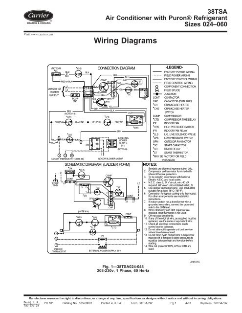
<strong>38TSA</strong><strong>Air</strong> <strong>Conditioner</strong> <strong>with</strong> <strong>Puron</strong>® <strong>Refrigerant</strong><strong>Sizes</strong> <strong>024</strong>–<strong>060</strong>Visit www.carrier.comWiring Diagrams(NOTE #9)*CHREDBLKorCOMPRED or BLKBLUSCL1BLKH208/230 1Ø L2 11 21 R CPOWER{23 23 YELSUPPLYYEL FEQUIP CONTBLKBRNGNDOFMYELBLUBRNBLK(NOTE #14)*HPS*LPSBLUBLUBLU/PNKBLK*LLSBLU/PNKBLKY G RINDOOR THERMOSTAT (NOTE #6)EQUIPGNDYGRL1INDOORTHERMOSTATYEL/PNKCONNECTION DIAGRAMBLKCAPYELYEL/PNKBRNINDOOR BLOWER MOTORBLUBLUYELSCHEMATIC DIAGRAM (LADDER FORM)*CHCONT11 21*CHS*CHS*HPS5 21*SRBLKIFR(NOTE #14)OFM*LPS*LLS*SCRIFRCOMPCRHCFCAPCCR*SCVIOT1EXTERNALPOWERSUPPLY24 V(NOTE #3)*ST+tT2LOGICT1 T3*CTDEXTERNAL POWER SUPPLY 24 VSCONT23 23CONT-LEGEND-+t *STFACTORY POWER WIRINGFIELD POWER WIRINGFACTORY CONTROL WIRINGFIELD CONTROL WIRINGCOMPONENT CONNECTIONBRNFIELD SPLICE1 2JUNCTION5CONT CONTACTOR*SRCAP CAPACITOR (DUAL RUN)*CH CRANKCASE HEATER*CHS CRANKCASE HEATERSWITCHCOMP COMPRESSORT2 *CTD COMPRESSOR TIME DELAYLOGICT3 IDF INDOOR FAN*CTD *HPS HIGH PRESSURE SWITCHIFR INDOOR FAN RELAY*LLS LIQ. LINE SOLENOID VALVE*LPS LOW PRESSURE SWITCHOFM OUTDOOR FAN MOTOR*SC START CAPACITOR*SR START RELAY*ST START THERMISTOR*MAY BE FACTORY OR FIELDINSTALLEDNOTES:1. Symbols are electrical representation only.2. Compressor and fan motor furnished <strong>with</strong>inherent thermal protection.3. To be wired in accordance <strong>with</strong> NationalElectric N.E.C. and local codes.L2 4. N.E.C. class 2, 24 V circuit, min. 40 VArequired, 60 VA on units installed <strong>with</strong> LLS.5. Use copper conductors only. Use conductorssuitable for at least 75°C (167°F).6. Connection for typical cooling only thermostat.For other arrangements see installationinstructions.7. If indoor section has a transformer <strong>with</strong> agrounded secondary, connect the groundedside to the BRN lead.8. When start relay and start capacitor areinstalled, start thermistor is not used.9. CH not used on all units.10. If any of the original wire, as supplied must bereplaced, use the same or equivalent wire.11. Check all electrical connections insidecontrol box for tightness.12. Do not attempt to operate unit until servicevalves have been opened.13. Do not rapid cycle compressor. Compressormust be off 3 minutes to allow pressures toequalize between high and low side beforestarting.14. Wire not present if HPS, LPS or CTD areused.Fig. 1—<strong>38TSA</strong><strong>024</strong>-048208-230v, 1 Phase, 60 HertzA98055Manufacturer reserves the right to discontinue, or change at any time, specifications or designs <strong>with</strong>out notice and <strong>with</strong>out incurring obligations.Book 1 4 PC 101 Catalog No. 533-80081 Printed in U.S.A. Form <strong>38TSA</strong>-2W Pg 1 4-03 Replaces: <strong>38TSA</strong>-1WTab 3a 2a
*CH(NOTE #9)208/230 1ØPOWERSUPPLYBLUBLUEQUIPGNDBLU/PNKREDBLKorRED or BLKL1L2 11 2113 23EQUIPGNDBLU(NOTE #14)*HPSY G RINDOOR THERMOSTAT(NOTE #6)YGRL1{BLK*LLSBLU/PNKBLKCONTIFRCONNECTION DIAGRAMCOMPBLUSBLKC HR CYELYEL FBLK BRNOFMYELYEL/PNK*LPSCRBLKBLKCAPYELINDOOR BLOWER MOTORBLUBLUYEL*SCBRNVIOEXTERNALPOWERSUPPLY24 V(NOTE #3)+tBRN*ST1 25*SRT2YEL/PNK LOGICT1 T3*CTDBRNSCHEMATIC DIAGRAM (LADDER FORM)*CHCONT11 21INDOOR THERMOSTAT*CHS*HPS*CHS5 21*SRBLK(NOTE #14)OFM*LLS*SC*LPSRIFRCOMPC RHCFCSCAP*CTD*ST+tT2LOGICT1 T3EXTERNAL POWER SUPPLY 24 VCONT23 13CONTL2CONTCAP*CH*CHSCOMP*CTDIDF*HPSIFR*LLS*LPSOFM*SC*SR*ST-LEGEND-FACTORY POWER WIRINGFIELD POWER WIRINGFACTORY CONTROL WIRINGFIELD CONTROL WIRINGCOMPONENT CONNECTIONFIELD SPLICEJUNCTIONCONTACTORCAPACITOR (DUAL RUN)CRANKCASE HEATERCRANKCASE HEATER SWITCHCOMPRESSORCOMPRESSOR TIME DELAYINDOOR FANHIGH PRESSURE SWITCHINDOOR FAN RELAYLIQ. LINE SOLENOID VALVELOW PRESSURE SWITCHOUTDOOR FAN MOTORSTART CAPACITORSTART RELAYSTART THERMISTOR*MAY BE FACTORY OR FIELD INSTALLEDNOTES:1. Symbols are electrical representation only.2. Compressor and fan motor furnished <strong>with</strong>inherent thermal protection.3. To be wired in accordance <strong>with</strong> NationalElectric N.E.C. and local codes.4. N.E.C. class 2, 24 V circuit, min. 40 VArequired, 60 VA on units installed <strong>with</strong> LLS.5. Use copper conductors only. Use conductorssuitable for at least 75°C (167°F).6. Connection for typical cooling only thermostat.For other arrangements see installationinstructions.7. If indoor section has a transformer <strong>with</strong> agrounded secondary, connect the groundedside to the BRN lead.8. When start relay and start capacitor areinstalled, start thermistor is not used.9. CH not used on all units.10. If any of the original wire, as supplied must bereplaced, use the same or equivalent wire.11. Check all electrical connections insidecontrol box for tightness.12. Do not attempt to operate unit until servicevalves have been opened.13. Do not rapid cycle compressor. Compressormust be off 3 minutes to allow pressures toequalize between high and low side beforestarting.14. Wire not present if HPS, LPS or CTD areused.Fig. 2—<strong>38TSA</strong><strong>060</strong>208-230v, 1 Phase, 60 HertzA03020Copyright 2003 CARRIER Corp. • 7310 W. Morris St. • Indianapolis, IN 4623138tsa2wManufacturer reserves the right to discontinue, or change at any time, specifications or designs <strong>with</strong>out notice and <strong>with</strong>out incurring obligations.Book 1 4 PC 101 Catalog No. 533-80081 Printed in U.S.A. Form <strong>38TSA</strong>-2W Pg 2 4-03 Replaces: <strong>38TSA</strong>-1WTab 3a 2a


