SMARTDRIVE MANUAL ADDENDUM B - Kollmorgen
SMARTDRIVE MANUAL ADDENDUM B - Kollmorgen
SMARTDRIVE MANUAL ADDENDUM B - Kollmorgen
Create successful ePaper yourself
Turn your PDF publications into a flip-book with our unique Google optimized e-Paper software.
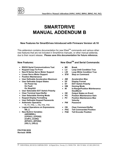
SmartDrive Manual Addendum (S6961, S6962, B8961, B8962, 961, 962)<strong>SMARTDRIVE</strong><strong>MANUAL</strong> <strong>ADDENDUM</strong> BNew Features for SmartDrives Introduced with Firmware Version v6.10This addendum contains documentation for new IDeal TM commands and various othernew features that are not included in SmartDrive manuals, or other manual addenda,due to their recent release. Please save this documentation for future reference.New Features:New IDeal TM and Serial Commands:• RS232 Serial Communications Test• Keypad Copy-To-From• New B Series Servo Motor Support• Linear Servo Motor Support• Position Maintenance• User Definable Acceleration Maximum• User Definable Output StatesOn Power-UpOn FaultOn Stop/Kill• User Selectable EOT Switch Polarity• Clear Terminal Input Buffer• User Selectable Homing Mode• Keypad Display Formatting• User Definable Keypad Passwords• Arithmetic Operators!=, ++, +=n, --, -=n, >>n,
SmartDrive Manual Addendum (S6961, S6962, B8961, B8962, 961, 962)INDUSTRIAL DEVICES CORPORATION 64 Digital Drive Novato, CA 94949-5704 800-747-0064 415-883-2094 FAX
SmartDrive Manual Addendum (S6961, S6962, B8961, B8962, 961, 962)Table of ContentsNew RUN Menu Option ................................................................................................................... 1Testing RS232 Serial Communications......................................................................................1New COPY Menu Option ................................................................................................................ 1Using keypad COPY-TO-FROM..................................................................................................1New System Configurations........................................................................................................ 2New Motor Configuration ..........................................................................................................2Configuring Stepper Motor Type....................................................................................2Configuring R-SRVO (Rotary) Servo Motor Type .......................................................2Configuring L-SRVO (Linear) Servo Motor Type.........................................................3New Encoder Configuration......................................................................................................4Configuring Encoder Mode (Position Maintenance) ...................................................4Configuring Position Maintenance Deadband .............................................................5Configuring Position Maintenance Gain .......................................................................5Configuring Position Maintenance Max Velocity .........................................................5New Mechanics Configuration .................................................................................................6Configuring Acceleration Maximum ..............................................................................6New Input & Outputs (I/O) Configuration ..............................................................................6Configuring Output States on Power Up ......................................................................6Configuring Output States on Fault...............................................................................7Configuring Output States on Stop / Kill.......................................................................7Configuring End of Travel Switch Polarity....................................................................7Configuring Input Definition (Clear Command Buffer)................................................7New HOME Parameters ..............................................................................................................8Configuring Homing Mode..............................................................................................8New Miscellaneous Setup Parameters...................................................................................9Configuring Display Format............................................................................................9Configuring Keypad Passwords...................................................................................10New and Updated IDeal TM Program Commands ...........................................................11BR Break Command..............................................................................................................11LU Loop Until Condition True Command............................................................................11LW Loop While Condition True Command..........................................................................12ST# Stop on Command ...........................................................................................................13New Arithmetic Operations........................................................................................................14New Operators............................................................................................................................14Incrementing and Decrementing Variables (++, +=, --, -=) ...............................................14Logical Operations on Expressions (&&, ||)........................................................................14INDUSTRIAL DEVICES CORPORATION 64 Digital Drive Novato, CA 94949-5704 800-747-0064 415-883-2094 FAX
SmartDrive Manual Addendum (S6961, S6962, B8961, B8962, 961, 962)Table of Contents (Continued)New Built-In Variables...................................................................................................................15(AROWREL) .................................................................................................................................15(CPOS1), (CPOS2)......................................................................................................................15(CUR1), (CUR2)...........................................................................................................................15(EPOS1), (EPOS2) ......................................................................................................................15(VEL1), (VEL2) .............................................................................................................................15Using the Built-In Variable (AROWREL) ..................................................................................15New and Updated Serial Commands ...................................................................................16New and Updated Serial Setup Commands ........................................................................16AM Acceleration Max................................................................................................16DF Display Format ...................................................................................................16EM Encoder Mode ....................................................................................................16ET End of Travel Switch Polarity............................................................................16HM Homing Mode .....................................................................................................17IR In-Range Window (B896X only).......................................................................17Position Maintenance Deadband (S696X, 96X only).....................................17IT In-Range Time (B896X only) ............................................................................17MT Motor Type ..........................................................................................................17OE Output States on Event......................................................................................18PG Position Maintenance Gain ...............................................................................18PV Position Maintenance Max Velocity..................................................................18PW Password..............................................................................................................18Updated Serial Supervisory Commands..............................................................................19SW Tell Software / Firmware Version......................................................................19New and Updated Serial Immediate Status Commands ..................................................19CB Clear Command Buffer......................................................................................19PA Tell Absolute Position.........................................................................................19INDUSTRIAL DEVICES CORPORATION 64 Digital Drive Novato, CA 94949-5704 800-747-0064 415-883-2094 FAX
New RUN Menu OptionSmartDrive Manual Addendum (S6961, S6962, B8961, B8962, 961, 962)The RUN > TEST > RS232 feature has now been implementedwhich allows for testing and debugging of daisy chain terminalcommunications through the keypad thus eliminating the need for aPC terminal connection.--------- ↓ RUN TEST ↑--------SHUTDN RS232 ENCODERTesting RS232 Serial CommunicationsRUN> TEST > RS232------ Test Connection -----TRANSMIT RECEIVEThis feature allows for testing of the terminal serial communications port through the keypad.Testing Serial Transmission:1. From the Test Connection menu press the F1 key to selectthe TRANSMIT option2. The SmartDrive will now transmit the string “ABC123”every 5 seconds.Testing Serial Receive:1. From the Test Connection menu press the F3 key to selectthe RECEIVE option2. Any character received on the terminal port will bedisplayed on the keypad.Test String ‘ABC123’Transmitting….Data Received:New COPY Menu OptionThe COPY TO-FROM feature has been implemented which allowsuser setup and programs to be downloaded to and from the keypad.A special keypad cable (PCS-5004) provides a +5V power supplyand a 9 pin D style connector for communications with ApplicationDeveloper . COPY TO-FROM requires SmartDrive version v6.00or higher and keypad firmware v2.60 or higher. Contact IDC forfirmware upgrades and cable information.--------------- COPY -------------PROG TO PAD FROMCopy To Keypad:1. Press F2 key to select TO PAD (Note: Unit address is not saved in keypad)Copy From Pad:1. Press F3 key to select FROM (Note: Unit address is not set from keypad transfer)In order to use COPY TO-FROM with Application Developer , connect the keypad to the PC usingcable PCS-5004 and select “Retrieve All” from the Application Developer Communications menuto load data from the keypad and select “Send All” from the Application Developer Communications menu to load data to the keypad. See the Application Developer section in theS696X, B896X and 96X manuals for more information on using Application Developer .INDUSTRIAL DEVICES CORPORATION 64 Digital Drive Novato, CA 94949-5704 800-747-0064 415-883-2094 FAX1
SmartDrive Manual Addendum (S6961, S6962, B8961, B8962, 961, 962)New System ConfigurationsNew Motor ConfigurationThe structure of the motor type selection menu has changed in orderto accommodate the addition of the built-in linear servo motor filesplus the expansion of the B servo motor series. The MOTOR TYPEmenu option now has three sub-menus: STEPER (for step motordrive parameters), R-SRVO (for rotary servo motors) and L-SRVO(for linear servo motors).------- MOTOR TYPE ------STEPER R-SRVO L-SRVOConfiguring Stepper Motor TypeEDIT> SETUP > MOTOR > TYPE > STEPERDefault: STEPPER (S696X)N/A(B896X)INDEXER (96X)-- Axis One Motor Type --←↓ STEPPER ↑→This menu option is fixed to type STEPPER in S696X SmartDrives.Configuring R-SRVO Motor Type [MT]EDIT> SETUP > MOTOR > TYPE > R-SRVODefault: N/A (S696X)NONE (B896X)INDEXER (96X)-- Axis One R-Srvo Type -←↓ B32: 110VAC ↑→This option specifies the type of rotary servo motor connected to the B896X SmartDrive andthe operating voltage level. The motor parameters used for drive configuration have beenspecifically tailored for IDC supplied rotary servo motors.1. Use the ← and → keys to select an axis2. Use the ↑ and ↓ keys to scroll through the list of IDC rotary motors3. Press the ESC key to selectConsult the factory if you intend to use a non-IDC rotary servo motor. See Chapter 7 of theB896X Brushless Servo SmartDrive manual RS-232 Operation for more information onconfiguring the SmartDrive for a non-IDC rotary servo motor.2INDUSTRIAL DEVICES CORPORATION 64 Digital Drive Novato, CA 94949-5704 800-747-0064 415-883-2094 FAX
SmartDrive Manual Addendum (S6961, S6962, B8961, B8962, 961, 962)Configuring L-SRVO Motor Type [MT]EDIT > SETUP > MOTOR > TYPE > L-SRVO-- Axis One L-Srvo Type -←↓ 2508: 110V 5u ↑→Default: N/A (S696X)NONE (B896X)INDEXER (96X)This option specifies the type of linear servo motor connected to the SmartDrive, the operatingvoltage level and the linear encoder resolution in microns. The motor parameters used for driveconfiguration have been specifically tailored for IDC supplied linear servo motors. Drive resolution,encoder resolution and gear ratio become fixed parameters and distance units are restricted to linearquantities when a L-SRVO motor type is selected. The default distance units for linear servo motorsis mm, the default velocity units are mm/s and default acceleration units are seconds. Linear motorsalso have built-in protection against accelerations exceeding 5g regardless of acceleration units or theAMAX parameter (See the New Mechanics Configuration: Configuring Acceleration Maximum[AM] of this addendum for more information on the AMAX parameter).1. Use the ← and → keys to select an axis2. Use the ↑ and ↓ keys to scroll through the list of IDC linear motors. Pressing the F1 keywill jump 8 items up the list and pressing the F3 key will jump 8 items down the list.3. Press the ESC key to selectConsult the factory if you intend to use a non-IDC linear servo motor. See Chapter 7 of theB896X Brushless Servo SmartDrive manual RS-232 Operation for more information onconfiguring the SmartDrive for a non-IDC linear servo motor.NOTE: The CL/CT force control features are currently not compatible with linearservo motors.New Encoder ConfigurationINDUSTRIAL DEVICES CORPORATION 64 Digital Drive Novato, CA 94949-5704 800-747-0064 415-883-2094 FAX3
SmartDrive Manual Addendum (S6961, S6962, B8961, B8962, 961, 962)A new encoder mode called CLOSED LOOP PM (PositionMaintenance) has been added to the selection list. Positionmaintenance provides post move closed loop “maintenance” of thelast commanded position. This feature gives stepper systems andservo systems with an encoder on the load position correctionability. It is not recommended or necessary to use positionmaintenance with B896X servo drive controls since the positionloop is already closed.-- ↓ ENCODER SETUP ↑--MODE E-RES FOL-ERRConfiguring Encoder Mode [EM]EDIT> SETUP > ENC > MODE---Axis One Enc Mode --←↓CLOSED LOOP PM↑→Default: OPEN LOOP (S696X, 96X)SERVO CLOSED (B896X)This option sets the encoder mode for each axis.1. Use ← and → keys to select an axis2. Use the ↑ and ↓ keys to scroll through the list of encoder modes and press ESC to select.Encoder ModeOPEN LOOPOPEN-STALLCLOSED LOOPSERVO-CLOSEDCLOSED LOOP PMDescriptionThe OPEN LOOP position will be displayed on the keypad.The OPEN LOOP position will be displayed on the keypad butthe encoder will be used for stall detection.The encoder position is displayed on the keypad. All moves arebased on encoder position and stall detection is enabled.The encoder position is displayed on the keypad. All moves arebased on the commanded OPEN LOOP position and stalldetection is enabled.The encoder position is displayed on the keypad. All moves arebased on encoder position, however, post move correctionalgorithms will keep the encoder position equal to the lastcommanded OPEN LOOP position. Following error is stillactive while in CLOSED LOOP PM mode. A following errorwill occur when the number of correction steps exceeds thefollowing error value. This allows the SmartDrive to signal afault when the displacement can not be corrected (i.e. the motoris stalled at an obstruction). Position maintenance will notattempt to correct position while navigating menus with thekeypad.4INDUSTRIAL DEVICES CORPORATION 64 Digital Drive Novato, CA 94949-5704 800-747-0064 415-883-2094 FAX
SmartDrive Manual Addendum (S6961, S6962, B8961, B8962, 961, 962)Configuring Position Maintenance Deadband [IR]EDIT> SETUP > ENC > IN-RANGE > WINDOWDefault: 25 motor stepsRange: 0 - 99999-Axis One PM DeadBnd-←↓ 25 Steps ↑→Position maintenance deadband is a user definable region surrounding the commandedposition in which the motor shaft can reside and not be considered “out of position”. Adisplacement position exceeding the last commanded position +/- the deadband value, willcause position maintenance to attempt to correct the position.1. Use ← and → keys to select an axis2. Use numeric keys to enter a new deadband value and press ENTER then ESC to register.NOTE: EDIT > SETUP > ENC > INRANGE > WINDOW and the IR serial commandhave an alternate functionality with servo SmartDrive systems. See the B8961/2 manualfor more details.Configuring Position Maintenance Gain [PG]EDIT> SETUP > ENC > PMGAIN--- Axis One PM Gain ---← 10 →Default: 10Range: 1 - 32767The position maintenance gain value is an integer factor used in determining the velocity atwhich the position maintenance correction move will travel. Correction velocity is calculatedas (displacement * correction gain) in units of steps/sec. Therefore, the larger thedisplacement, the faster position maintenance will attempt to correct position. For example,if the correction gain is set to 3 and an active displacement of 3200 steps occurs, thecorrection velocity will be (3 * 3200) = 9600 steps/sec.1. Use ← and → keys to select an axis2. Use numeric keys to enter a new position maintenance gain and press ENTER then ESCto register.Configuring Position Maintenance Max Velocity [PV]EDIT> SETUP > ENC > PMMAXDefault: 1 RPSRange: 0.005 - 9999999---- Axis One PM Max ---← 1 RPS →The position maintenance maximum velocity value sets a velocity limit in which positionmaintenance will attempt to correct position. Regardless of the magnitude of displacement orcorrection gain, the correction velocity will never exceed the maximum velocity setting.1. Use ← and → keys to select an axis2. Use numeric keys to enter a new position maintenance max velocity in the same unitsselected in the SETUP > MECH > VEL menu and press ENTER then ESC to register.INDUSTRIAL DEVICES CORPORATION 64 Digital Drive Novato, CA 94949-5704 800-747-0064 415-883-2094 FAX5
SmartDrive Manual Addendum (S6961, S6962, B8961, B8962, 961, 962)New Mechanics ConfigurationA new mechanics option AMAX (Acceleration Maximum) hasbeen added for setting acceleration limits.----- ↓ MECH SETUP ↑-----AMAXConfiguring Acceleration Maximum [AM]EDIT> SETUP > MECH > AMAX-- Axis One Max Accel --← 0.002 sec →Default:Range:0.002 {acceleration units}0.002 - 99999999 {acceleration units}Acceleration maximum sets a maximum acceleration and deceleration limit for programmedmove profiles in the current acceleration units. Programmed accelerations and decelerationsfor moves will be limited by this parameter (analogous to VMAX for velocity). Regardlessof acceleration units, the absolute maximum acceleration is 0.002 seconds.1. Use ← and → keys to select an axis.2. Use numeric keys to enter a new acceleration maximum in the same units selected in theSETUP > MECH > ACCEL menu and press ENTER then ESC to register.New Inputs & Outputs (I/O) ConfigurationTwo new I/O setup options, OUTSTS and LIMITS, have beenadded. OUTSTS (Output States on Event) allows user configurationof output states after power-up, fault or a Stop/Kill. LIMITS allowsuser configuration of the EOT (End of Travel) switch polarity. Alsoa new configurable input CLR CMD BUFFER “c” has been added.-------- ↓ I/O SETUP ↑-------OUTSTS LIMITS-- OUTPUT STATES ON --PWR-UP FAULT ST / KConfiguring Output States on Power Up [OEP]EDIT > SETUP > I/O > OUTSTS > PWR-UPDefault: OFF-- On PwrUp Output #1 -←↓ OFF ↑→This option sets the desired states of the outputs on power up.1. Use ← and → keys to scroll through outputs #1- #8 and any OPTO positions configuredas outputs.2. Use the ↑ and ↓ keys to set the output state as OFF or ON and press ESC to register.6INDUSTRIAL DEVICES CORPORATION 64 Digital Drive Novato, CA 94949-5704 800-747-0064 415-883-2094 FAX
SmartDrive Manual Addendum (S6961, S6962, B8961, B8962, 961, 962)Configuring Output States on Fault [OEF]EDIT > SETUP > I/O > OUTSTS > FAULTDefault: NO CHANGE--- On Fault Output #1 ---←↓ NO CHANGE ↑→This option sets the desired states of the outputs on a fault.1. Use ← and → keys to scroll through outputs #1- #8 and any OPTO positions configuredas outputs.2. Use the ↑ and ↓ keys to set the output state as OFF, ON or NO CHANGE and press ESCto register.Configuring Output States on Stop / Kill [OES]EDIT> SETUP > I/O > OUTSTS > ST / KDefault:NO CHANGE-- On ST / K Output #1 -←↓ NO CHANGE ↑→This option sets the desired states of the outputs on a Stop or Kill.1. Use ← and → keys to scroll through outputs #1- #8 and any OPTO positions configuredas outputs.2. Use the ↑ and ↓ keys to set the output state as OFF, ON or NO CHANGE and press ESCto register.Configuring End of Travel Switch Polarity [ET]EDIT> SETUP > I/O > LIMITSDefault:NORM CLOSED---- Axis One EOT Pol ---←↓ NORM CLOSED ↑→This option allows configuration of the EOT switch polarity as NORM OPEN or NORMCLOSED to accommodate the use of either type of switch.1. Use ← and → keys to select an axis.2. Use the ↑ and ↓ keys to select NORM OPEN or NORM CLOSED and press ESC toregister.Configuring Input Definition [ID]EDIT> SETUP > I/O > > INPUTSIN1: CLR CMD BUFFERcUUUUUUU-------- ←↓ ↑→Default:UUUUUUUUNew Input Character Descriptionc Clear Command BufferClears the terminal input buffer and buffered command bufferINDUSTRIAL DEVICES CORPORATION 64 Digital Drive Novato, CA 94949-5704 800-747-0064 415-883-2094 FAX7
SmartDrive Manual Addendum (S6961, S6962, B8961, B8962, 961, 962)New HOME ParametersThe home setup parameters have been expanded to include ahoming mode selection option which determines how the GHcommand functions.----- ↓ HOME SETUP ↑----MODE EDGE SWITCHConfiguring Homing Mode [HM]EDIT> SETUP > HOME > MODE-- Axis One Home Mode -←↓ SWITCH ONLY ↑→Default: SWITCH ONLY (Any OPEN LOOP encoder mode)SWITCH THEN Z (Any CLOSED LOOP encoder mode)The homing mode parameter establishes how a Go Home (GH) command will executehoming routines.1. Use ← and → keys to select an axis2. Use the ↑ and ↓ keys to scroll through the list of homing modes and press ESC to select.Homing ModeSWITCH ONLYSWITCH THEN ZZ CHANNEL ONLYDescriptionGH will only home to the appropriate edge of the home switchregardless of encoder mode. This is the only mode availablewithout an encoder.GH will home to the switch, align to the edge and then slowlymove until an encoder Z pulse is found. This mode requires anencoder.GH will slowly move until an encoder Z pulse is found. The stateof the home switch is ignored. The magnitude of the GH velocityparameter is ignored. The sign of the GH velocity parameterdetermines the low speed direction. This mode requires anencoder.8INDUSTRIAL DEVICES CORPORATION 64 Digital Drive Novato, CA 94949-5704 800-747-0064 415-883-2094 FAX
SmartDrive Manual Addendum (S6961, S6962, B8961, B8962, 961, 962)New Miscellaneous Setup ParametersThe Display Format (DISP) feature has now been implemented aswell as the addition of user definable keypad password protection(PASWRD).------ ↓MISC SETUP ↑------DISP STOP-RATE TEST------ ↓MISC SETUP ↑------FAULT ENABLE PASWRDConfiguring Display Format [DF]EDIT > SETUP > MISC > DISP< Quad #1 > Quad #2Quad #3 Quad #4Default: Quad #1: POS1Quad #2: POS2 (dual axis units)------ Quad #1 Display -----BLANK (single axis units)Quad #3: INPUTSQuad #4: OUTPUTS↓ INPUTS ↑Display format allows the user to customize the data displayed on the keypad run timescreen. The run time screen has been divided into 4, 10 character configurable quadrants.The DISP menu displays labels for the 4 quadrants with carets (< >) denoting the selectedquadrant.1. Use ← ,→, ↑ and ↓ keys to move quadrant selection delimiters (< >).2. Press ENTER to edit quadrant.Once a quadrant is selected, there are 16 possible data types that can be displayed in thatquadrant.Data TypeQuadrant DisplayBLANK No displayPOS1 Axis #1 positionPOS2 Axis #2 positionPOS1+UNIT Axis #1 position with axis unitsPOS2+UNIT Axis #2 position with axis unitsVEL1 Axis #1 commanded velocityVEL2 Axis #2 commanded velocityCUR1 Axis #1 current in Amps (B896X only)CUR2 Axis #2 current in Amps (B896X only)INPUTS Discreet input status (0 off, 1 on)OUTPUTS Discreet output status (0 off, 1 on)OPTOS OPTO input and output status (0 off, 1 on) as configuredSA_STATUS1 Displays SA serial command response for axis #1SA_STATUS2 Displays SA serial command response for axis #2SS_STATUS Displays SS serial command responseTEXT Display user defined text in a quadrant3. Use the ↑ and ↓ key to scroll through the data types and press ESC to register all datatypes except TEXT (see below).4. In order to define a text field, scroll to the TEXT data type and then press the ALPHAkey or a number key. A cursor will appear allowing up to 10 characters to be entered.Type the desired text, press the ENTER key and then press ESC to register.INDUSTRIAL DEVICES CORPORATION 64 Digital Drive Novato, CA 94949-5704 800-747-0064 415-883-2094 FAX9
SmartDrive Manual Addendum (S6961, S6962, B8961, B8962, 961, 962)Configuring Keypad Passwords [PW]EDIT > SETUP > MISC > PASWRD----PASSWORD SETUP----OPRATR ADMIN CLEARDefault: NoneIn addition to the keypad dip switches, user definable passwords allow restricted access tothe RUN, EDIT, COPY and DEL menus.1. From the PASWORD SETUP menu, press F1 to enter an OPRATR password or press F2to enter an ADMIN password.2. Enter password using a maximum of 4 alpha-numeric characters only (0-9, A-Z and a-zonly). See S696X, B896X and 96X manuals on how to enter alpha-numeric data on thekeypad.3. Press ENTER to register the password and ESC to exit.Defined PasswordsOPRATR onlyADMIN onlyOPRATR with ADMINADMIN with OPRATRMenu AccessibilityRUN, EDIT, COPY, DELRUN, EDIT, COPY, DELRUN only (All RUN functions except TEST)RUN, EDIT, COPY, DELIf no passwords are defined, there are no menu restrictions.If passwords are defined, pressing RUN, EDIT, COPY orDEL will display the password prompt. Entering the wrongpassword or pressing ESC at the password prompt willreturn the keypad to the standard run-time display.Selecting EDIT > SETUP > MISC > PASWRD > CLEARwill delete all passwords.NOTE: Once a valid password is entered, the passwordprompt is replaced by the USE LAST, RESET prompt.Select USE LAST (F1) to use the last entered password orRESET (F3) to require the password to be reentered (i.e.require the next user to enter the password). This allows forsubsequent use of the RUN, EDIT, COPY and DEL keyswithout requiring the password to be entered each time.Enter Password:>PasswordUSE LASTRESET10INDUSTRIAL DEVICES CORPORATION 64 Digital Drive Novato, CA 94949-5704 800-747-0064 415-883-2094 FAX
SmartDrive Manual Addendum (S6961, S6962, B8961, B8962, 961, 962)New and Updated IDeal TM Program CommandsBRBreak.................................................................. syntax - BRThe Break command instantly “breaks” a loop block in which it is defined and continuesprogram execution from the loop’s terminating EB command. This allows for morecomplex loop conditioning than LU or LW commands.Example:(A)=0 {Define variable A}(B)=0 {Define variable B}LP{Define loop block}IF(A)>10 {Check if A is greater than 10}IF2,0{Check if input #2 is off}BR{Break loop}EBEB(A)++ {Increment variable A by 1}EB{BR command jumps here}MS1,”A is greater than 10” {Display message}LULoop Until Condition True…………………… syntax - LUn (See Below)The LU command defines a loop block in which loop iterations are based on a conditionalresult. The syntax for LU, which is identical to the IF command, is as follows:Syntax(s): LUn,xx…LUxx…(assumes first input is input 1)LU(Mathematical expression)Range: n = starting input number, 1-16 (SmartDrive)x = 0, (Input Off)x = 1 (Input On)x ≠ 0 or 1 (Input level ignored)Mathematical expression = Any valid conditional or logical expressionThe LU loop will continue to iterate until the specified conditional is true. LU checks theconditional at the end of the loop block, therefore regardless if the conditional is true onthe first iteration, the block is executed at least once. See the LW (Loop WhileConditional True) to define loops where the conditional is checked at the beginning of theloop block. LU follows the same constraint of 16 nested blocks as the IF and LPcommands. A GT command within a LU loop will terminate the loop, clear the loopstack and jump to the new program.NOTE: An End of Block (EB) command must be used with every LU command.Example #1: This loop is executed 11 times with a final position of 110 distance units.INDUSTRIAL DEVICES CORPORATION 64 Digital Drive Novato, CA 94949-5704 800-747-0064 415-883-2094 FAX11
SmartDrive Manual Addendum (S6961, S6962, B8961, B8962, 961, 962)(A)=0 {Define variable A}LU(A)=10 {Loop until A = 10}DI10 GO{Move 10 distance units}(A)++ {Increment variable A}EB{End loop}Example #2: This loop is executed once since the (A)
SmartDrive Manual Addendum (S6961, S6962, B8961, B8962, 961, 962)NOTE: An End of Block (EB) command must be used with every LW command.Example #1: This loop is executed 11 times with a final position of 110 distance units.(A)=0 {Define variable A}LW(A)20 condition is false.(A)=10 {Define variable A}LW(A)>20 {Loop while A is greater than 20}DI10 GO{Move 10 distance units}EB{End loop}Example #3: This loop will continue to execute as long as inputs #3 and #5 are on.LWXX1X1MS1,”Inputs 3 & 5 are on”EBGT[Inputs Off]{Loop while inputs #3 and #5 are on}{Display message}{End loop}{Jump to program}Example #4: This loop will continue to execute as long as input #4 is on.LW4,1MS1,”Input 4 is on”EBGT[Input Off]{Loop while input #4 is on}{Display message}{End loop}{Jump to program}STStop on Input or Command……………… syntax – STn,n or ST#n,#nUnits: N/ARange: 0-16 (Inputs)1-2 (Axes)ST#n,#n Syntax:ST#1 command stops move execution on axis #1. ST,#2 stops move execution on axis#2. ST#1,#2 stops move execution on both axes.ST#n functions identically to the STn command without the use of an input allowingprogram command conditional motion termination. The motor is stopped at thedeceleration rate specified in the Stop Decel Rate setup parameter.Example: Move to absolute position of 6 distance units. If (A) > 10, motion is stopped.AC1,1 VE25,25 DA6,6 GI {Move to 6 absolute distance units and GO Immediate}IF(A)>10{Check value of A (Assume A was previously defined)}ST#1 TD1 ST,#2 {Stop motion on axis #1 wait 1 sec then stop axis #2}EBST#1,#2{Stop motion on both axes}INDUSTRIAL DEVICES CORPORATION 64 Digital Drive Novato, CA 94949-5704 800-747-0064 415-883-2094 FAX13
SmartDrive Manual Addendum (S6961, S6962, B8961, B8962, 961, 962)New Arithmetic OperationsNew OperatorsOperator Description!= Not Equal++ Single Increment+=n Value Increment by n-- Single Decrement-=n Value Decrement by n>>n Shift Right by n
SmartDrive Manual Addendum (S6961, S6962, B8961, B8962, 961, 962)New Built-In VariablesVariable Name Description Type(AROWREL) Current status of any on the 4 arrow keys (SeeRead-onlyexplanation below)(CPOS1), (CPOS2) Commanded position of axis 1-2 Read-only(CUR1), (CUR2) Motor current in Amps (B896X only) Read-only(EPOS1), (EPOS2) Encoder position of axis 1-2 Read-only(VEL1), (VEL2) Commanded velocity of axis 1-2 Read-onlyUsing the Built-In Variable (AROWREL)(AROWREL) is a built-in Boolean read only variable which determines the status of any ofthe 4 arrow keys. When used in conjunction with (FKEY), the user can detect whether or notan arrow key is being held down. (AROWREL) will return one of the following values:(AROWREL) = 0(AROWREL) = 1One of the arrow keys is being held down.The arrow key has been released.(AROWREL) will return key status for the 4 arrow keys only. If any other key is pressed,(AROWREL) will return zero regardless if the key is held down or not. The following is anexample jog application using (AROWREL) and (FKEY):[MAIN] {Program #1}FK12,13{Wait for a Left or Right arrow key}GT(FKEY) {Jump to arrow key program #12 or #13}[LEFTARROW] {Program #12}MC+{Enable MC mode}AC.1{Start MC move}VE1{Move in positive direction}GOLPIF(AROWREL)=1 {Check status of arrow key}VE0{Stop MC move on key release}GOGT1{Return to main program}EBEB{End loop block}[RIGHTARROW] {Program #13}MC+{Enable MC mode}AC.1{Start MC move}VE-1{Move in negative direction}GOLPIF(AROWREL)=1 {Check status of arrow key}VE0{Stop MC move on key release}GOGT1{Return to main program}EBEB{End loop block}INDUSTRIAL DEVICES CORPORATION 64 Digital Drive Novato, CA 94949-5704 800-747-0064 415-883-2094 FAX15
SmartDrive Manual Addendum (S6961, S6962, B8961, B8962, 961, 962)New and Updated Serial CommandsNew and Updated Serial Setup CommandsCommand Command Description SyntaxAM Acceleration MaxSets the acceleration maximum (Units selected by AUcommand).AMr,rDFEMETDisplay FormatConfigures the 4 keypad run time display quadrants. DFtakes 4 parameters where i is an integer representing adisplay data type per quadrant. User defined text is limitedto 10 characters per field.i = 0 BLANK1 POS12 POS23 POS1 + UNIT4 POS2 + UNIT5 VEL16 VEL27 CUR18 CUR29 INPUTS10 OUTPUTS11 OPTOS12 SA_STATUS113 SA_STATUS214 SS_STATUS“User defined text in quotes”Example: DF1,5,11,”Text Here”Encoder ModeSelects the encoder modei = 0 OPEN LOOP1 OPEN-STALL2 CLOSED LOOP3 SERVO-CLOSED4 CLOSED LOOP PMEnd of Travel Switch PolaritySelects the polarity of the EOT (End of Travel) switches.i = 0 NORM OPEN1 NORM CLOSEDDFi,i,i,iDF”Text”,i,i,iEMi,iETi,i16INDUSTRIAL DEVICES CORPORATION 64 Digital Drive Novato, CA 94949-5704 800-747-0064 415-883-2094 FAX
SmartDrive Manual Addendum (S6961, S6962, B8961, B8962, 961, 962)New and Updated Serial Setup CommandsCommand Command Description SyntaxHM Homing ModeHMi,iSelects homing modei = 0 SWITCH ONLY1 SWITCH THEN Z2 Z CHANNEL ONLYIRIRITMTIn-Range Window (B896X only)Sets In-Range window in motor stepsPosition Maintenance Deadband (S696X,96X only)Sets position maintenance deadband in motor steps Valid asa program command using an immediate parameter only(No variables).In-Range Time (B896X only)Sets In-Range time limit within In-Range Window inmillisecondsMotor TypeSelects a built-in motor type. Note: Linear motor types arenegative.i = 0 NONE1 B23: 110V -1 2504: 110V 10µ -30 3804: 220V 1µ2 B23: 220V -2 2504: 220V 10µ -31 3804: 110V 0.5µ3 B32: 110V -3 2504: 110V 5µ -32 3804: 220V 0.5µ4 B32: 220V -4 2504: 220V 5µ -33 3806: 110V 10µ5 B41: 110V -5 2504: 110V 1µ -34 3806: 220V 10µ6 B41: 220V -6 2504: 220V 1µ -35 3806: 110V 5µ7 H3: 110V -7 2504: 110V 0.5µ -36 3806: 220V 5µ8 H4: 110V -8 2504: 220V 0.5µ -37 3806: 110V 1µ9 OTHER -9 2506: 110V 10µ -38 3806: 220V 1µ10 B12: 110V -10 2506: 220V 10µ -39 3806: 110V 0.5µ11 B22: 110V -11 2506: 110V 5µ -40 3806: 220V 0.5µ12 B22: 220V -12 2506: 220V 5µ -41 3808: 110V 10µ13 B23H: 110V -13 2506: 110V 1µ -42 3808: 220V 10µ14 B23H: 220V -14 2506: 220V 1µ -43 3808: 110V 5µ15 B31: 110V -15 2506: 110V 0.5µ -44 3808: 220V 5µ16 B31: 220V -16 2506: 220V 0.5µ -45 3808: 110V 1µ17 B33: 110V -17 2508: 110V 10µ -46 3808: 220V 1µ18 B33: 220V -18 2508: 220V 10µ -47 3808: 110V 0.5µ19 B40: 110V -19 2508: 110V 5µ -48 3808: 220V 0.5µ20 B40: 220V -20 2508: 220V 5µ -49 3810: 110V 10µ21 B42: 110V -21 2508: 110V 1µ -50 3810: 220V 10µ22 B42: 110V -22 2508: 220V 1µ -51 3810: 110V 5µ23 B42: 220V -23 2508: 110V 0.5µ -52 3810: 220V 5µ24 BN21: 110V -24 2508: 220V 0.5µ -53 3810: 110V 1µ25 BN23: 110V -25 3804: 110V 10µ -54 3810: 220V 1µ26 BN31: 110V -26 3804: 220V 10µ -55 3810: 110V 0.5µ27 BN32: 110V -27 3804: 110V 5µ -56 3810: 220V 0.5µ-28 3804: 220V 5µ -57 OTHER-29 3804: 110V 1µIRi,iIRi,iITi,iMTi,iINDUSTRIAL DEVICES CORPORATION 64 Digital Drive Novato, CA 94949-5704 800-747-0064 415-883-2094 FAX17
SmartDrive Manual Addendum (S6961, S6962, B8961, B8962, 961, 962)New and Updated Serial Setup CommandsCommand Command Description SyntaxOE Output States on EventConfigures output states on an event specified by a. OPTOpositions 9-16 are only definable if configured as an outputusing OP command.OEa,iiiiiiiiiiiiiiiia = P (Power-Up)F (Fault)S (Stop / Kill)i = 0 Off1 OnX No ChangeExample: OEF,0001XX01XXXXXXXXPGPVPWPosition Maintenance GainSets position maintenance correction gain.i = 1 to 32,767Position Maintenance Max VelocitySets position maintenance maximum correction velocity(Units specified by VU command).PasswordSpecifies the OPRATR and ADMIN keypad menurestriction passwords. The syntax for the PW command isPWOPRATR,ADMIN. Passwords can be a maximum of 4characters consisting of numerical digits 0-9 or upper andlower case alpha characters A-Z. Specifying a dash (-) willclear the respective password and a null parameter willleave the respective password unchanged. Passwords cannot be retrieved using the UA command. The following areexamples using PW:Example #1: PW4FT,Q12hThis would set the OPRATR password to 4FT and theADMIN password to Q12h.Example #2: PW,NewThis would change the ADMIN password to New and leavethe OPRATR password unchanged.Example #3: PW-,-This would clear both the OPRATR and ADMINpasswords.PGi,iPVi,iPWaaaa,aaaa18INDUSTRIAL DEVICES CORPORATION 64 Digital Drive Novato, CA 94949-5704 800-747-0064 415-883-2094 FAX
SmartDrive Manual Addendum (S6961, S6962, B8961, B8962, 961, 962)Updated Serial Supervisory CommandsCommand Command Description SyntaxSW Software/Firmware VersionSW returns firmware versionSW1 returns DSP, FPGA and firmware versionsSWSW1New and Updated Serial Immediate Status CommandsCommand Command Description SyntaxCB Clear Command BufferCBClears the terminal input buffer and buffered commandbufferPA Tell Absolute PositionReports current position in user units based on encodermode selected. Can report specifically commanded orencoder position when PAa,n is used.PAnPAa,na = C (Commanded Position)E (Encoder Position)n = 1-2 axisExamples: PA2 Returns axis #2 encoder mode positionPAC,1 Returns axis #1 commanded positionINDUSTRIAL DEVICES CORPORATION 64 Digital Drive Novato, CA 94949-5704 800-747-0064 415-883-2094 FAX19
SmartDrive Manual Addendum (S6961, S6962, B8961, B8962, 961, 962)INDUSTRIAL DEVICES CORPORATION 64 Digital Drive Novato, CA 94949-5704 800-747-0064 415-883-2094 FAX


