SMART DRIVE MANUAL ADDENDUM - Kollmorgen
SMART DRIVE MANUAL ADDENDUM - Kollmorgen
SMART DRIVE MANUAL ADDENDUM - Kollmorgen
You also want an ePaper? Increase the reach of your titles
YUMPU automatically turns print PDFs into web optimized ePapers that Google loves.
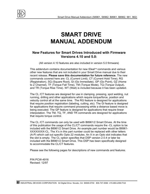
Smart Drive Manual Addendum (S6961, S6962, B8961, B8962, 961, 962)<strong>SMART</strong> <strong>DRIVE</strong><strong>MANUAL</strong> <strong>ADDENDUM</strong>New Features for Smart Drives Introduced with FirmwareVersions 4.10 and 5.0:(All version 4.10 features are also included in version 5.0 firmware)This addendum contains documentation for new IDeal commands and variousother new features that are not included in your Smart Drive manual due to theirrecent release. Please save this documentation for future reference. The newcommands covered here are: CL (Current Limit), CT (Current Hold Time), RG(Registration), SQ (Square Root), GI (Go Immediate), GP (Go Point), GZ (Hometo Z Channel), TF (Torque Fall Time), TM (Torque Mode), TQ (Torque Output),and TR (Torque Rise Time). WT (Wait) is included because it has been updated.The CL /CT features are designed for use in clamping, pressing, spot welding, nutrunning, drilling and other applications which require torque/force, position andvelocity control all at the same time. The RG feature is designed for applicationsthat require position registration (labeling, cutting, etc). The GI feature is designedfor applications that require command processing while a distance based move isbeing executed. The GP feature is designed for applications that require linearinterpolation. The TM, TQ, TF, AND TR commands are designed for applicationsthat require torque control.The CL /CT commands can only be used with B8961/2 Smart Drives. At the timeof this publication the usage of the CL/CT commands require the -CL option to beincluded with the B8961/2 Smart Drive. An example part number would be B8961-XXXXXXXX-CL. The X’s in this part number could be replaced with other letters(A-P) which call out specific Opto 22 modules. An X in an Opto slot indicates thatthe slot is empty. The CL option specifies that DSP version 2.0.4 or later beincluded with the B8961/2 Smart Drive. This DSP has been specifically designedto accommodate the CL/CT features.Please see the following pages for descriptions of new commands and features.P/N PCW-4916Revised: 12/97INDUSTRIAL DEVICES CORPORATION 64 Digital Drive Novato, CA 94949-5704 800-747-0064 415-883-2094 FAX
Smart Drive Manual Addendum (S6961, S6962, B8961, B8962, 961, 962)INDUSTRIAL DEVICES CORPORATION 64 Digital Drive Novato, CA 94949-5704 800-747-0064415-883-2094 FAX
Smart Drive Manual Addendum (S6961, S6962, B8961, B8962, 961, 962)Table of ContentsNew Command Descriptions...........................................................1Commands Introduced with Firmware Version 4.10 ............................................ 1CL (Current Limit) .......................................................................................... 1CT (Current Hold Time) ................................................................................. 3GZ (Home to Z Channel) ............................................................................... 3RG (Registration) ........................................................................................... 4SQ (Square Root) .......................................................................................... 5Commands Introduced with Firmware Version 5.0 .............................................. 6GI (Go Immediate) ......................................................................................... 6GP (Go Point) .............................................................................................. 10TF (Torque Fall Time).................................................................................. 11TM (Torque Mode)....................................................................................... 10TQ (Torque Output) ..................................................................................... 12TR (Torque Rise Time)................................................................................ 12WT (Wait)..................................................................................................... 13Configuring New Setup Parameters - CLAMP .............................14New Inputs & Outputs....................................................................15Programming Your Application.....................................................18New Built-in Variables ........................................................................................ 18Programming/Application Notes......................................................................... 19New RS-232C Commands..............................................................21INDUSTRIAL DEVICES CORPORATION 64 Digital Drive Novato, CA 94949-5704 800-747-0064 415-883-2094 FAX
Smart Drive Manual Addendum (S6961, S6962, B8961, B8962, 961, 962)INDUSTRIAL DEVICES CORPORATION 64 Digital Drive Novato, CA 94949-5704 800-747-0064415-883-2094 FAX
New Command DescriptionsCommands Introduced with Firmware Version 4.10:Smart Drive Manual Addendum (S6961, S6962, B8961, B8962, 961, 962)CLCurrent Limit ……………………………………………. syntax - CLn,nUnits: Amps or % Torque (Selected from the EDIT > SETUP > CLAMP menu)Range: Unit scaling dependentThis command is only valid with the B8961/2 SmartDrives.The CL command sets a current limit (in user units) to “clamp” the motor current to whileexecuting a move. Reaching this current limit is dependent on the commanded move andthe encountering of a load inducing a current rise in the motor windings equal to the CLvalue. If the current limit is reached in the move, the control switches from position mode totorque mode on the fly and maintains a torque level (or force level if an actuator is used)proportional to the CL value. If no load is encountered in a CL defined move that induces acurrent rise to the CL value, the move executes like a standard position based move.The desired torque output from a motor can be determined by multiplying the torqueconstant of the motor (K T ) by the motor current limit set by CL. The following table givesthe nominal K T values of IDC motors. Due to variance in individual motor windings, the K Tvalue can vary ±10% from the nominal.K T Values for IDC Motors (oz.in/Amp)B23 B32 B41 H3 H457.6 99.2 187 54 67CL is compatible with the DC (Distance to a Change) command (Please see the DCcommand description in your B8961/2 manual for more details on this command). Use ofCL with the DC command allows the user to specify different current limits for differentsections of the move profile. The current limit will change once the motor has traveled thedistance specified by the DC command which precedes the CL command. This meansthat one section of the move can have the full peak torque available in order to do a fastaccel, while another section of the move can have a lower current limit in order to lightlypress or clamp a part. When defining both a new velocity (VE) and current limit (CL) aftera DC command specify the VE value first. This will allow the new velocity to be comparedto the Break Velocity when determining when a torque mode runaway condition is present.Unlike conventional position based moves which are terminated when the commandeddistance is reached (DA and DI based moves), or Mode Continuous (MC) moves whichare done (command processing continues after the GO) when the commanded velocity isreached, a CL move is meant to be terminated by the CT (Current Hold Time) commandor an ST (Stop on Input) command (See CT and ST command descriptions for moredetails).There are, however, built in safety features in the B8961/2 Smart Drive to protect yourmachine by terminating a CL defined move when the commanded distance is reachedwhile in torque mode, and terminating the move when the commanded move velocity (orbreak velocity, whichever is higher) is exceeded while in torque mode. These features aremeant to prevent machine hard stops due to broken or mis-fed parts.INDUSTRIAL DEVICES CORPORATION 64 Digital Drive Novato, CA 94949-5704 800-747-0064 415-883-2094 FAX1
Smart Drive Manual Addendum (S6961, S6962, B8961, B8962, 961, 962)When a CL move ends, the drive’s current limit is automatically reset to its default value (fullrated peak torque of the motor) to provide full available torque for the next move. This allowsfor a ‘quick return’ stroke back to home using full available peak torque after a clamping orpressing operation.WARNING - The correct Encoder Mode setting for operating CL/CT is SERVO-CLOSED.This is the default operating mode for all servos. CL/CT will not work properly in otherEncoder Modes.The following are some example programs demonstrating CL syntax and conventions:Example #1: Basic CL move which terminates on an input. This will execute a normal DA moveunless the CL current limit is achieved. The system will remain clamped until input #1 isasserted. Assume CL units are Amps.VE1CL2.25ST1DA2.5GOSet velocity to 1 user unitSet current limit to 2.25 AmpsTerminate “clamping” when input #1 is assertedMove 2.5 user unitsBegin the moveExample #2: Basic CL move which terminates the clamping or pressing operation afterholding the CL specified current for the time specified by the CT command. Assume CL unitsare Amps.VE,1 Set velocity to 1 user unit on axis #2CL,1.5 Set current limit to 1.5 Amps on axis #2CT,1.2 Set “clamping” time for 1.2 seconds on axis #2DA,2 Move 2 user units on axis #2GOBegin the moveExample #3: The CL command is compatible with the DC command. Assume CL units areamps. This move will not invoke the CL3 current limit until an absolute distance of 1.2 userunits is reached. Therefore, there is no limit set on the motor current during the move fromdistance 0 to distance 1.2. This enables the motor to execute a fast accel without the CLcommand limiting the acceleration rate.AC.05VE1DA2DC1.2 CL3GOSet Acceleration to .05 secsSet velocity to 1 user unitMove 2 user unitsAt an absolute distance of 1.2, invoke a current limit of 3 AmpsBegin the moveExample #4: This program demonstrates programming with CL units of % Torque{Move #1} CL50.5 ST1 DA2.5 GO DA0 GO{Move #2} CL200 ST1 DA2.5 GO DA0 GOMove #1 will clamp with a force of 50.5% of the motor’s RMS current limit. For a B23, this would be1.26 amps. For a B32, this would be 2.42 amps. Move #2 will clamp with a force of 200% of themotor’s RMS limit. For a B23, this would be 5 amps. For a B32, this would be 9.6 amps.2INDUSTRIAL DEVICES CORPORATION 64 Digital Drive Novato, CA 94949-5704 800-747-0064415-883-2094 FAX
Smart Drive Manual Addendum (S6961, S6962, B8961, B8962, 961, 962)CTCurrent Hold Time…………………………………….. syntax - CTn,nUnits: SecondsRange: 0 to 99999.99 secondsThis command is only valid with the B8961/2 SmartDrives.The CT command sets the time in seconds that a CL defined current is held. Once thetime set by CT has been reached, the CL defined move terminates, and the controlswitches back to position mode automatically. Current Hold Time can be specified inincrements of 0.001 seconds. The CT command can be changed as a function ofdistance traveled by using the DC command.GZHome to Z Channel ................................................. syntax - GZ±This command will rotate the motor in the direction specified by ± until the encoder Zpulse is encountered. This command does not require home switches and issometimes used in rotary applications to eliminate the need for a home switch.The GZ command will home very slowly to ensure that the Z pulse is not missed.Program Example:GZ+ DA10 VE1 AC.1 GOGZ+DA10VE1AC.1GO{Home to Z channel of the encoder, rotate motor in the positivedirection to look for Z channel. After homing to the Z channel of theencoder, the position will be set to the Home Offset}{Define absolute distance of 10 user units}{Set velocity to one}{Set Acceleration to 0.1 second}{Start move}INDUSTRIAL DEVICES CORPORATION 64 Digital Drive Novato, CA 94949-5704 800-747-0064 415-883-2094 FAX3
Smart Drive Manual Addendum (S6961, S6962, B8961, B8962, 961, 962)RGRegistration ..............................................syntax - RGn or RG,nThe Registration Command (RG ) specifies a distance to be indexed from the currentposition - as commanded by a specific input trigger. The RG command must appearafter a DA or DI in any program, and the RG parameter must be positive (+)regardless of the sign (+ or -) of the DA or DI command.For example, in the program below an absolute distance of 10 user-units on axis #1 iscommanded, the input trigger is received at user-unit 4, and the motor moves 3 userunitsfrom the point where the input trigger was received. This results in a final positionof 7 user units.DA10 VE2 AC.1 RG3 GOIn the program above, assume the input was an optical sensor which triggered on aregistration mark at a position of 4 user-units. The figure below shows the commandedmove relative to what the registration move would be.VelocityRG InputTriggerRGEnd of Move1 2 3 4 5 6 7 8 9 10RG IndexDistanceCommandedDistanceAccompanying the programmable Registration Command is the configurableRegistration Input: G (also G in RS-232C Setup Commands). To configure aRegistration input from the keypad, choose EDIT > SETUP > I/O > INPUTS. An inputconfigured as a Registration Input will be designated by a G on the keypad input statusdisplay. The RG Command will only function if the corresponding input has beenconfigured as a Registration Input (see note).Note: Registration Input is only configurable on Input #1 for Axis #1,and on Input #2 for Axis #2.System Performance when Using the RG (Registration) CommandThere is a Capture Window (Position Lag) associated with the RG Command, which isa function of move velocity and the Position Capture Delay (reaction time) and can becalculated with the following equation:Capture Window = RG Position Capture Delay * Velocity (Steps/Sec)The Capture Window value is the number of steps accumulated between the fallingedge of the Registration input and the time the current position is captured. Dependingon the FPGA hardware version of your Indexer this RG Position Capture Delay willeither be 164 µs or 5 µs.The Registration Command is only available on firmware version 4.0 & higher. If youhave FPGA version 5.9 or earlier, the Capture Delay will be 164 µs. If you have FPGA6.7 or higher, the position is captured in hardware, and the only Capture Delay is the4INDUSTRIAL DEVICES CORPORATION 64 Digital Drive Novato, CA 94949-5704 800-747-0064415-883-2094 FAX
Smart Drive Manual Addendum (S6961, S6962, B8961, B8962, 961, 962)input’s opto-isolator (5 µs). Use the keypad’s HELP key to determine your FPGAversion.Regardless of the FPGA version used, we have found both Capture Delays to beextremely repeatable. This leads to a very repeatable Capture Window (distance lagfrom when the registration input is made) that can be accounted for by decreasingyour commanded registration distance by the Capture Window. For example, a motortraveling 240,000 steps/sec (30 rps with 8000 step/rev drive resolution) has a capturewindow of 39 steps for a 164 µs Capture Delay and 1 step for a 5 µs Capture Delay.Assuming the desired registration distance was 3 user units (and assuming 1 user unitis 8000 motor steps), an RG2.9795 would result in the motor traveling exactly 3 userunits for a unit with a 164 µs Capture Delay.SQSquare Root…………………………………… syntax - SQn,(var)Range: 0.0001 to 214748.3645The SQ command calculates the square root of a number and returns the result in auser defined variable. The n parameter in the syntax can be a number or a variableparameter, however, the second parameter must be a previously defined variable forwhich the square root result is stored. If the second parameter is not a definedvariable, you will get a Bad Variable Name error. Following mathematical convention,SQ will produce an Invalid Parameter error for negative n values. The return value isaccurate to the 0.01 place.Example: The following example program calculates the square root of 27.96 andstores the value in the user defined variable (SQRESULT).Program:(SQRESULT)=0 SQ27,(SQRESULT)The returned value in (SQRESULT) would be 5.28.INDUSTRIAL DEVICES CORPORATION 64 Digital Drive Novato, CA 94949-5704 800-747-0064 415-883-2094 FAX5
Smart Drive Manual Addendum (S6961, S6962, B8961, B8962, 961, 962)Commands Introduced with Firmware Version 5.0:GIGo Immediate……………………………………………….……syntax - GIThe GI command begins a defined move profile in the same manner as the GOcommand. Unlike the GO command, where program execution waits until all definedmoves have terminated, GI allows program execution to continue once the move hasbegun. This allows for other program defined processes to take place while an axis ismoving, such as independent multi-axis moves, OT commands, and conditional IFblocks. One axis is not required to wait for another axis to finish a move beforebeginning its own move.Following is an example of a program using the GI command:VE1 DI20 GI MS1, “Axis #1 is moving” TD2In this example, once the DI20 move begins, program execution immediately displaysthe “Axis #1 is moving” message for 2 seconds. Once the TD2 command hasexecuted, the program will terminate; however, axis #1 will continue to move until theDI20 distance is reached. A Stop, Kill, or press of the ESC key will halt a GI basedmove either inside or outside program execution.The GI command can cause program execution and moves to be asynchronous. Inorder to re-synchronize the end of a GI move with program execution, use the Waitcommand and its new syntax, i.e. WT#1 will wait for only axis #1; WT,#2 will wait foronly axis #2; WT#1,#2 will wait until both axes have stopped.If a program error occurs during a GI move, the move will stop at the Stop Decel Rate.USING THE GI COMMAND - EXAMPLESThe following examples are provided to help further explain the use of the command:A. If a GI move is in progress and an additional move is commanded on the sameaxis, the additional move will not begin until the GI move has completed. Forexample:VE1 DA100 GI OT1,1 DA0 GI IF1,1 MS1,”All moves done” EBIn this program, one may expect to see the message “All moves done”immediately after the DA100 move begins. In reality, the program will wait at theDA0 GI until the DA100 move has completed before continuing. More simplystated, a move cannot be commanded to begin on an axis that is already moving.B. For multi-axis systems, GI allows moves within a move. For example:VE1 DA100 GI LP5 VE,10 DI,5 GO EB6INDUSTRIAL DEVICES CORPORATION 64 Digital Drive Novato, CA 94949-5704 800-747-0064415-883-2094 FAX
Smart Drive Manual Addendum (S6961, S6962, B8961, B8962, 961, 962)C. Since GI allows program execution to continue, there can be programming issueswhen using GI. For example, in the following program fragment:LP VE2 DI10 GI OT1 TD1 OT0 EBVThe program above willfunction as shown hereAxis 1Output 1V.1 second 1 secondTTNOT as shown hereAxis 1Output 1After the first pass through, the loop command (LP) will wait at the GI commandsince subsequent GI moves must wait for the present move to finish.D. Another issue is programming conditional GI moves within IF blocks, for example:LP IF1,1 VE5 DI20 GI OTXX100 EB IF2,1 MC,+ VE,10 GO EB IF3,1 VE,0 GO EB EBIn this program, when input #1 is asserted, the GI move will be commanded,however, since the program will continue executing, input #1 may still be assertedon the next loop iteration. This will cause a second GI move to be commandedwhich may be undesirable. To avoid this situation, the addition of a WT1,0 afterthe IF1,1 will insure that input #1 is only seen once since it has to be deactivatedto allow the program to continue.VAxis 1VTAxis 2TINDUSTRIAL DEVICES CORPORATION 64 Digital Drive Novato, CA 94949-5704 800-747-0064 415-883-2094 FAX7
Smart Drive Manual Addendum (S6961, S6962, B8961, B8962, 961, 962)E. DI1 GI DI,5 GO DI1 GIF. DI10 GI DI,2 GO DI,2 GO DI10 GIVAxis 1TVAxis 2T8INDUSTRIAL DEVICES CORPORATION 64 Digital Drive Novato, CA 94949-5704 800-747-0064415-883-2094 FAX
Smart Drive Manual Addendum (S6961, S6962, B8961, B8962, 961, 962)G. (VAR1)=10 {Initialize Variable}LP{Beginning of Loop Block}DI55,10{Define Two Axis Move}VE10,10AC.5,.5GI{Start Go Immediate Move Both Axes}MS1,’’’’{Clear Screen}MS1,(AI9){Write Analog Input 9 to the Screen While Moving}WT,#2{Wait for Axis 2 to Stop Moving}TD.5{Time Delay of 0.5 seconds}DI,10{Define Axis 2 Move of 10 units}GI{Start Axis 2 GO Immediate Move}IF8,1{If Input 8 is on}OT10,1 {Turn on Output 10}TD.1{Time Delay of 0.1 seconds}OT10,0 {Turn off Output 10}EB{End of If Block}WT,#2{Wait for Axis 2 to Stop Moving}TD.5{Time Delay of 0.5 seconds}DI,10GI{Start Axis 2 Go Immediate Move}(DIST)=(VAR1)*1000 {Do Variable Math while Moving}(TERM)=(DIST) {Send Value of DIST Variable out of Serial Port}WT,#2{Wait for Axis 2 to Stop moving}OT2,1 {Turn On Output 2}WT#1{Wait for Axis 1 to Stop Moving}OT1,1 {Turn On Output 1}DA0,0GO{Move Both Axes Back to Starting Position}EB{End of Loop Block, Restart Loop}EN{End of Program}V10Axis 100.5 5.5 6.0 tV10Axis 200.5 1.5 2.0 3.5 4.0 5.5 6.0 tINDUSTRIAL DEVICES CORPORATION 64 Digital Drive Novato, CA 94949-5704 800-747-0064 415-883-2094 FAX9
Smart Drive Manual Addendum (S6961, S6962, B8961, B8962, 961, 962)GPGo Point (Linear Interpolation)………………….……syntax - GP or GPnThe GP command allows the Smart Drive to execute a linear interpolated move. Anexample of the GP move is as follows:YThe units and values for path velocity, acceleration and deceleration in GP moves arespecified by the parameters traditionally defined for an axis #1 based move. As inregular moves, velocity, acceleration, and deceleration only need to be defined once.Each sequential GP move thereafter will use these values until new values areentered. The endpoint of the move is specified by a two axis DA or DI commandwhich corresponds to the appropriate X and Y coordinates. The following programwould execute the move in the picture:VE2 AC.1 DA4,2 GPThe path velocity is 2 user units/sec, path acceleration is .1 sec and the X,Y positionwould be (4,2).The GPn syntax is identical to the GOn command. GPn pre-calculates the move andwaits for Input number “n” to activate before executing. For example, GP4 would precalculatethe move and wait for input 4 to be active before executing.Although both axis move during a GP defined move, all GP parameters refer to thepath movement rather than to the individual axis movements.NOTES ON GP:(4,2)The largest possible GP moves are restricted to X 2 + Y 2
Smart Drive Manual Addendum (S6961, S6962, B8961, B8962, 961, 962)TFTorque Fall Time……………….………………………………………..TFn,nThis command is only valid with the B8961/2 Brushless Servo Smart Drives.The TF command specifies the time in seconds to ramp torque output down from ahigher to lower value. If the drive has not been placed in torque mode by a TMcommand, the TF command is disabled. (Please see TM command documentationfor more details).The syntax for the command is TFn,n where the comma denotes the axis and thevalue n denotes the desired time in seconds of the torque fall ramp. The TFcommand is programmable in seconds only and does not support rates of change. If aDA or DI move is executed on one axis, while a TQ move is in effect on another, theTF and TQ parameters should be respecified on the next TQ command block issued.An example of a typical program using the TF command is shown below:TM1 TQ1 TR1 GO TD5 TQ0 TF0.5 GOThe TM command is required to place the drive in torque mode and enable the use oftorque control commands. The TQ1 command programs a constant torque output of 1amp. The TR1 command specifies a torque rise time to 1 amp of 1 second (Pleasesee TR documentation for more details). The TD5 command specifies a time delay of5 seconds while a torque proportional to 1 amp is maintained. The TF0.5 commandspecifies a fall time to 0 torque in 0.5 seconds.The TF command cannot be used with CL/CT commands.TMTorque Mode……………………………………………………………..TMn,nThis command is only valid with the B8961/2 Brushless Servo Smart Drives.The TM command places the drive in torque mode where motor torque can be directlycommanded. The syntax for the command is TMn,n where the comma denotes theaxis. The values of n are defined below:n = 1 Places the axis in torque mode and enables the torque controlcommands.n = 0 Places the axis back to position mode and disables the torque controlcommands.The TM command is used in conjunction with the torque control commands TQ, TR,and TF. These commands are analogous to the position mode commands VE, ACand DE. They determine the torque output level and rate of torque increase anddecrease respectively. Please see documentation on these commands for furtherdetails. The TM command must be issued before any torque control commandsbecome valid.The CL/CT (Current Limit/Current Hold Time) commands are not considered torquecontrol commands and represent an entirely different approach to torque/force control.INDUSTRIAL DEVICES CORPORATION 64 Digital Drive Novato, CA 94949-5704 800-747-0064 415-883-2094 FAX11
Smart Drive Manual Addendum (S6961, S6962, B8961, B8962, 961, 962)Please see documentation on the CL/CT commands for further details. It is importantto note that placing the drive in TM mode does not invoke the features and safetyprotocols of the CL/CT commands.TQTorque Output……………………………………………………………..TQn,nThis command is only valid with the B8961/2 Brushless Servo Smart Drives.The TQ command specifies the torque output of the motor when the drive has beenplaced in torque mode using the TM command (Please see TM commanddocumentation for more details). If the drive has not been placed in torque mode by aTM command, the TQ command is disabled.The syntax for the command is TQn,n where the comma denotes the axis and thevalue n denotes the desired torque output in units of Amps or % Torque. TQ units aredefined under EDIT-SETUP-CLAMP-UNITS menu or by using the RS232 commandCU. Please see the CL/CT documentation for details on torque units and restrictions.An example of a typical program using the TQ command is shown below, assumeunits of Amps:TM1 TQ0.75 GO WT1,1 TQ0 GOThe TM command is required to place the drive in torque mode, and enable the use oftorque control commands. TQ0.75 programs a constant torque output of 0.75 amps.When input #1 is asserted, TQ0 brings the system down to 0 amps and 0 torque.Usingthe ESC key, or issuing a STOP/KILL input or command, will also terminate a TQmove, and reset the drive to position mode.Unlike the CL/CT commands, motor position is ignored while in torque mode, andmore importantly, the features and safety protocols of CL/CT are not active.Therefore, if a TQ command is issued and the motor is not loaded or the load is “lost”,the motor will accelerate to a high velocity torque runway situation.TRTorque Rise Time………………….………………………………………..TRn,nThis command is only valid with the B8961/2 Brushless Servo Smart Drives.The TR command specifies the time in seconds to ramp torque output up from a lowerto higher value. If the drive has not been placed in torque mode by a TM command,the TR command is disabled. (Please see TM command documentation for moredetails).The syntax for the command is TRn,n where the comma denotes the axis and thevalue n denotes the desired time in seconds of the torque rise ramp. The TRcommand is programmable in seconds only and does not support rates of change.Like the AC command, TR will set both rise and fall ramps unless a separate torquefall time is programmed by a TF command (Please see AC and TF documentation formore details). If a DA or DI move is executed on one axis while a TQ move is in effect12INDUSTRIAL DEVICES CORPORATION 64 Digital Drive Novato, CA 94949-5704 800-747-0064415-883-2094 FAX
Smart Drive Manual Addendum (S6961, S6962, B8961, B8962, 961, 962)on another, the TF and TQ parameters should be respecified on the next TQcommand block issued.An example of a typical program using the TR command is shown below:TM1 TQ1 TR1 GO TD2 TQ0 GOThe TM command is required to place the drive in torque mode and enable the use oftorque control commands. The TQ1 programs a constant torque output of 1 amp. TheTR1 specifies a torque rise time to 1 amp of 1 second. The TD2 command causes themotor torque to be held at a constant value for 2 seconds. The TQ0 command willcause the torque to be ramped down to 0 amps in 1 second since there was no TFcommand issued.The TR command cannot be used with CL/CT commands.WTWait ................................................................syntax - see belowSyntax(s): WTn,xx...WTxx... (assumes first input is input 1)WT(AIn), expressionRange: n = starting input number, 1-16x = 0; input highx = 1; input low (grounded)x = anything but 1 or 0; ignore the input levelexpression = any valid expression as defined in the math and variablessection.This command waits for the specified condition to be true before continuing executionof a program. Either digital or analog input conditions may be used.To increase flexibility the WT command allows you to use configured inputs in theexpression. To help prevent this added flexibility from causing programmingconfusion, you can specify any character as an input (x). This allows you to selfdocument your WT statements. For example, assume you configured input #3 as a“JOG SPEED” input. Programming like “WT01J10” can help remind you that you arealready using input # 3.Note: In order to synchronize program execution with the end of a GI move, there isnew syntax associated with the WT (Wait) command. WT#1,#2 will halt programexecution until the respective axis has completed its move. WT#1 will wait for onlyaxis #1; WT,#2 will wait for only axis #2; WT#1,#2 will wait until both axes havestopped.Example:WT14,1 GOWT12,010 GOWT110 GOWT(AI9)< 45000 GOWait for input 14 to equal 1 before movingWait for inputs 12-14 to equal 010 before movingWait for inputs 1-3 to equal 110 before movingWait for analog input 9 < 45000 before movingINDUSTRIAL DEVICES CORPORATION 64 Digital Drive Novato, CA 94949-5704 800-747-0064 415-883-2094 FAX13
Smart Drive Manual Addendum (S6961, S6962, B8961, B8962, 961, 962)Configuring New Setup Parameters - CLAMPConfiguring Clamp Units [CU]EDIT> SETUP > CLAMP > UNITSDefault: AmpsYou can choose between AMPS or % TORQUE as the units of the CL command. Thevalid parameter range for AMPS is 0 < X < (Rated RMS Current of Motor) and %TORQUE is0 < X < 285%. The following table illustrates these ranges:B23 B32 B41 H3 H4Rated RMS Current 2.5 Amps 4.8 Amps 4.6 Amps 2.5 Amps 5 AmpsRated Peak Current 7.2 Amps 10 Amps 10 Amps 6 Amps 10 AmpsMax % Torque 285% 200% 200% 240% 200%While programming CL in units of AMPS, if a number greater than the rated RMS currentof the motor is commanded, the motor current is clipped to the motor’s rated RMS current.Units of % TORQUE allow you to program currents above the RMS value of the motor.100% corresponds to the rated RMS current of the motor. For example, if using a B32motor the rated RMS current is 4.8 Amps, so a CL100 would command a 4.8 Ampclamping current from the motor. By entering values above 100% you can achieve currentlimit values above the motor’s rated RMS current, however, clamping at values above theRMS value for extended periods of time will generate an RMS current fault. If a value over285% is entered (2.85 times the motor’s RMS rating) or [(% TORQUE)*(Rated RMSCurrent)] > [Rated Peak Current], the current to the motor is clipped to the Rated PeakCurrent.1. Use ← and → keys to select an axis.2. Use ↑ and ↓ keys to select AMPS or % TORQUE.Configuring Break Velocity [BV]EDIT> SETUP > CLAMP > BRKVELDefault: 5 {Velocity Units}This feature inhibits a torque mode runaway condition if the load is “lost” while at the CLlimit (i.e. the object clamped breaks or slips). For moves where the break velocity isgreater than the move velocity, the break velocity will be used as the trigger point wherethe control switches from torque mode to position mode. After this switch takes place, themotor will decelerate to the commanded move velocity. For moves with a higher movevelocity than the break velocity setting, the move velocity will be used as the trigger pointwhere the control switches back to position mode from torque mode. This feature allowsan actuator to press smoothly at low speeds where stiction (bouncing back and forthbetween static and kinetic coefficients of friction) is present while still having torque moderunaway safety control.Caution: It is recommended to set the break velocity only slightly higher than the movevelocity. Too high a break velocity setting can cause the control to jump in and out oftorque mode if the break velocity is exceeded while executing a CL defined move.14INDUSTRIAL DEVICES CORPORATION 64 Digital Drive Novato, CA 94949-5704 800-747-0064415-883-2094 FAX
Smart Drive Manual Addendum (S6961, S6962, B8961, B8962, 961, 962)1. Use ← and → keys to select an axis.2. Use the numeric keys to set the break velocity in VE units.New Inputs & OutputsConfiguring Input Definition [ID]EDIT> SETUP > I/O > INPUTSDefault: UUUUUUUUUUUUUUUUSee Configuring Your Inputs & Outputs (I/O) in your SmartDrive manual for more detailson input definition.1. Use ← and → keys to select an Input. The function of the highlighted input will bedisplayed on the top line.2. Once your cursor is on the desired input, use ↑ ↓ to select F (SET CL FORCE 1) or f(SET CL FORCE 2).New Input Character DescriptionsF,f Set CL Force (F specifies axis 1, f specifies axis 2)In addition to being able to set a clamping current via the CL command, the user can alsoset the clamp current on the fly based on an input. When the SET CL FORCE input isasserted during a CL defined move, the control will maintain the torque the motor isproducing at that instant. For example, if the following move is executing: VE1 CL3 DA3GO (CL units are Amps), and a SET CL FORCE input is activated when the motor currentis at 1.5 amps, the current will be clamped to 1.5 amps. If this input is not triggered, thecontrol will clamp the current to 3 amps. The SET CL FORCE input requires a valid CLmove to be in progress otherwise the input is ignored. The SET CL FORCE input isintended for applications clamping to load cell feedback.I Interrupt (Run 98)When activated, motion on all axes is stopped at the stop-rate (see Edit-Setup-Misc-Stop-Rate). The current program is stopped, and processing continues with the first commandin program 98. If no program is running when the input is activated, program 98 will run.This input is ignored while the keypad is in Edit mode. This is a positive edge sensitiveinput, rather than a level sensitive input. If multiple inputs are configured as Interrupts, onlythe first edge of the first activated input will be seen. If subsequent Interrupt inputs goactive while the first Interrupt input is active, no additional interrupts will be seen.Advanced Interrupt handling can be achieved using the (INT98CTRL) and (ARM INT98)variables. The (INT98CTRL) variable determines whether Interrupts can be disabled ornot. The (ARM INT98) variable allows you to arm and disarm the Interrupt as desired.When the Indexer powers up (INT98CTRL) is initialized to 0. In this mode, every interruptresults in an immediate jump to program 98, even if you just entered program 98. Thismeans that it is possible for the interrupt service routine to be interrupted by anotherinterrupt input. This functionality is backwards compatible with earlier versions of firmwarein IDC SmartDrives. The value of (ARM INT98) is ignored.INDUSTRIAL DEVICES CORPORATION 64 Digital Drive Novato, CA 94949-5704 800-747-0064 415-883-2094 FAX15
Smart Drive Manual Addendum (S6961, S6962, B8961, B8962, 961, 962)When (INT98CTRL)=1 you can enable and disable Interrupts at will with the (ARM INT98)variable. Setting (INT98CTRL)=1 also initializes (ARM INT98) to 1. This means thecontrol is watching for interrupts. When (INT98CTRL) is set to 1 an interrupt causes theprogram tojump to program 98 AND sets (ARM INT98)=0, disabling any further interrupts until you reenablethem by setting (ARM INT98)=1. This allows you to control when you want to reenableInterrupts in your interrupt service routine (program 98).To summarize, when (INT98CTRL)=1:If (ARM INT98)=0Interrupts are ignored. (ARM INT98) is automatically set to 0 by the Smart Drive on thefirst edge of the input, if the previous (ARM INT98) value was 1. Interrupt processing willbe suspended until (ARM INT98) is reset to 1. This allows for input debouncing and givesthe user control over the ability of program 98 to interrupt itself.If (ARM INT98)=1The system is awaiting the first INT98 input assert edge. Once the interrupt is seen thecontrol will go to program 98. Subsequent interrupts are ignored until (ARM INT98) is setto 1.(INT98CTRL) and (ARM INT98) are reset to default values on power-up.Note: There is a space in (ARM INT98).VData ValidWhen this input is configured, it determines if the Binary/BCD program select lines areprocessed or ignored. If the input is active, program select lines are processed, otherwisethey are ignored. This allows applications to be wired in a pseudo-bus architecture fashionwith each unit sharing the same program select lines, and the data valid inputsdetermining which units should listen. Configuring this output can greatly reduce panelwiring.In the example shown below, using the Data Valid input reduced the number of wiresrequired for selecting programs by one-half.961#4961#3961#2961#14321Data ValidUnitSelectionPLCProgramSelection16INDUSTRIAL DEVICES CORPORATION 64 Digital Drive Novato, CA 94949-5704 800-747-0064415-883-2094 FAX
Configuring Output Definition [OD]Smart Drive Manual Addendum (S6961, S6962, B8961, B8962, 961, 962)EDIT> SETUP > I/O > OUTPUTSDefault: PPPPPPPP--------See Configuring Your Inputs & Outputs (I/O) in your SmartDrive manual for more detailson output definition.1. Use ← and → keys to select an Output or OPTO output channel. The function of thehighlighted output will be displayed on the top line.2. Once your cursor is on the desired output, use ↑ ↓ to select K (AT CL LIMIT 1) or k(AT CL LIMIT 2).New Output Character DescriptionsK,k At CL Limit (K specifies axis 1, k specifies axis 2)The AT CL LIMIT output will become active when the motor current reaches the valuedefined by CL in the user’s program. This output allows the Servo SmartDrive to indicateto a PLC when it has begun clamping, so that the user may synchronize the clampingoperation with other processes in the application (for example drilling, cutting, or milling theclampedpart).INDUSTRIAL DEVICES CORPORATION 64 Digital Drive Novato, CA 94949-5704 800-747-0064 415-883-2094 FAX17
Smart Drive Manual Addendum (S6961, S6962, B8961, B8962, 961, 962)Programming Your ApplicationNew Built-In VariablesThe following are new pre-defined variable names that can be used in torque controlapplications.Variable Name Description Type(CLSTAT1), (CLSTAT2) Value of CL termination code Read only(TORQLIM1),(TORQLIM2)Displays/sets the current torqueoutput limit of the amplifierRead andWrite(CLSTAT1) axis 1, (CLSTAT2) axis 2The CLSTAT variable is a status variable which reports how a CL based move terminated.The following table shows the possible values of CLSTAT and their meaning:CLSTAT ValueDescription0 Never clamped, reached the commanded move distance1 Clamped, stopped on a ST input2 Clamped, stopped on a CT time out3 Clamped then exceeded commanded move velocity or breakvelocity (whichever is greater) causing control to switch back intoposition mode4 Clamped then exceeded commanded move distanceThese status variables are useful in pressing applications (for example, pressing bearingson a journal) where part variances could effect how well two parts are pressed together.The user commands the following clamping move to repeatedly press bearings ontojournals coming down an assembly line:LP WT1 ST2 DA5 VE2 AC1 CL1.125 CT5 GO EBIn the above program the control waits for input #1 to go active before proceeding toclamp. If input #2 is ever activated during the clamping operation, the move is aborted. Ifboth parts are within tolerance, the CL defined motor current is reached (1.125 amps), andthe move terminates after the current has been held for 5 seconds. If part tolerances aretoo loose, the CL value is never reached and the move will terminate at the specified movedistance (5 inches). If the part breaks during clamping, the motor will accelerate up to thedefined move velocity, 2”/sec, and then will switch back into position mode and finish themove after the actuator has traveled 5 inches. An external event could also occur where apremature exit of the clamping operation is desired. This can be accomplished byactivating input 2 which halts the clamping operation via the ST2 command in the program.Depending on how the clamping operation ended the CLSTAT value is set to thecorresponding termination value.(TORQLIM1) axis 1, (TORQLIM2) axis 2The TORQLIM variable is for positioning applications that require a safety limit to be set onmotor torque and where it is undesirable to switch to torque mode when this limit isreached. This variable allows the user to set the maximum motor current available fromwithin a program and stay in position mode when this current is reached. The units ofTORQLIM are Amps. For example, a sample program is:(TORQLIM1)=2 DA1.125 VE3 AC1 GO18INDUSTRIAL DEVICES CORPORATION 64 Digital Drive Novato, CA 94949-5704 800-747-0064415-883-2094 FAX
Smart Drive Manual Addendum (S6961, S6962, B8961, B8962, 961, 962)The above program sets the maximum motor current equal to 2 Amps. If the motorencounters a load while executing the above move that forces a current rise in the motorwindings equal to 2 Amps, the motor current will be clipped to 2 Amps. However, thecontrol will not switch into torque mode when 2 Amps is reached, and will instead stay inposition mode.This torque limiting feature is useful for pressing applications where the user would like topress a part with a set amount of force until a distance is reached. For example, if the useris pressing bearings onto a journal it may be desirable to press the part with a motortorque proportional to 2 Amps of current until a distance of 1.125” is reached (see theexample program above).Due to motor current (and thus available torque) being limited by the TORQLIM variable itis more likely that the user will get a Following Error when executing a move. There aretwo ways to solve this problem: increase the Following Error setting for the control(found in EDIT>SETUP>ENC>FOL-ERR) or increase the value of the TORQLIM variable.If neither of these solutions is appropriate for the application, it is recommended to use theCL/CT features of the product and switch into torque mode when the current limit isreached.When TORQLIM is set to a value, the control writes the value to RAM. This value is kept inRAM until TORQLIM is redefined or until the power is cycled. The TORQLIM value is resetto the motor default when power is cycled.Programming/Application Notes - CL/CT• Usage of CL/CT with the DC command allows the user to maximize throughput whileallowing the actuator to encounter the load at a relatively low velocity before currentlimiting. This minimizes impact forces and prolongs the life of the mechanics being used.After a CL defined move is complete, the available motor torque is reset to the defaultvalue of the motor to allow for an aggressive ‘quick return’ stroke. An example of aclamping move with a quick return stroke is:DA10 VE20 AC.1 DC7 VE2 DC8.2 CL2.1 CT7 GO DA0 VE30 GOThis program commands a move distance of 10 inches, an acceleration/deceleration of0.1 seconds, and an initial move velocity of 20 inches/sec. Since no CL value wasspecified before the first DC command, the full available motor torque is present toaccelerate the motor up to 20”/sec in 0.1 seconds. Once the motor has reached a distanceof 7 inches, the motor decelerates to a speed of 2”/sec in 0.1 sec.Note that no CL value was specified after the DC7 command, so full motor torque isavailable for decelerating the motor from 20”/sec to 2”/sec during this section of the move.While decelerating from 20”/sec to 2”/sec, the motor travels 1.1”. This means that wehave reached 8.1” (absolute distance from zero) when we start running at a constantspeed of 2”/sec. At a distance of 8.2” the motor current is limited to 2.1 amps by the CL2.1command. While running at 2”/sec a load is encountered and the motor current is clampedto 2.1 amps, and held for 7 seconds. After the clamp is complete the motor makes a quickreturn move back to the zero position.• After completing a clamping, pressing, or fixturing operation the drive will switch fromtorque mode back into position mode. This switch typically causes some ringing in themotor’s position as the drive is now servoing to position as opposed to torque.INDUSTRIAL DEVICES CORPORATION 64 Digital Drive Novato, CA 94949-5704 800-747-0064 415-883-2094 FAX19
Smart Drive Manual Addendum (S6961, S6962, B8961, B8962, 961, 962)• CL/CT commands are valid over RS-232C. This allows for a computer to stream downcurrent limiting moves (CL/CT moves) via Terminal in ‘hosted mode’ without having todefine a program. For example: CL5 CT.2 DI2.25 VE1 AC.3 GO is a valid set of movecommands from terminal.• When the distance commanded by a CL defined move is reached while in torque modethe B8961/2 will switch out of torque mode and back into position mode and subsequentlybring the motor to a stop at the programmed decel rate. This can occur in pressingapplications. This switch into position mode will result in a final position that exceeds thecommanded move position. The switch from torque mode to position mode when themove distance is met is intended as a safety feature, and is not meant to bring the motorto a stop at the commanded move distance.• Pressing the ESC key or activating a Stop, Kill, or Interrupt (Run 98) input when thesystem is clamped will abort the move and program as usual.• When executing loops, CL/CT commands must appear within the LP block and within theGO block in which they are intended to be active. For example:LP DI5 VE2 CL3 CT.5 GO EB {valid syntax, CL/CT defined within LP and GO block}CL3 CT.5 LP DI5 VE2.3 GO EB {invalid, CL/CT not defined within LP and GO block}• Two axis moves that include clamping behave just like any other two axis move: bothmoves must be “complete” before program flow continues after the GO command. Thismeans that if Axis 1 has finished an indexing move, and Axis 2 is in torque mode waitingfor the CT time to expire, Axis 1 must wait for Axis 2 to finish before Axis 1 can moveagain.• It is recommended to slow the motor down to a low speed before encountering the load.This will minimize impact forces the mechanics are subjected to by the application, therebyprolonging their life.• An IDC R-Pack may be required with the B8961/2 to dissipate the regenerative energycaused by CL/CT applications. The need for an R-Pack in your application will be indicatedby your B8961/2 faulting while performing a move, and displaying anOvervoltage/Overcurrent Fault on the keypad display. If you do not possess a keypad, youcan detect the nature of the fault by using the SA and SD immediate RS-232 commands(Please see the Immediate RS-232 Status Command section of your B8961/2 manual).• The Force output from a screw-driven actuator while it is moving can be determined from the2πfollowing equation: F = Tm × p × GR × eff × effS16GB, where F is force in units of lb(f),Tm is motor torque in units of oz-in, P is the pitch of the leadscrew (revs/in), GR is the gearratio, eff s isthe efficiency of the leadscrew, and eff GB is the efficiency of the gearbox. The Force2πoutput from a screw-driven actuator that is stationary is: F= × Tm× GR×P16as above).(units same20INDUSTRIAL DEVICES CORPORATION 64 Digital Drive Novato, CA 94949-5704 800-747-0064415-883-2094 FAX
Smart Drive Manual Addendum (S6961, S6962, B8961, B8962, 961, 962)New RS-232C Commands - Introduced in Firmware Version 4.10Command Name RS-232C SyntaxAA Auto Address AA or AAnThe AA command automatically addresses Smart Drives in a daisy chain. Itassigns a device address to each unit on the daisy chain. This allows the units tobe wired in a daisy chain without setting each unit’s address manually. The AAcommand parameter n indicates the value in which the addressing sequence willbegin.HostRXTX1 st Unitassigned4RXTX2 nd Unitassigned5RXTX3 rd Unitassigned6RXTX4 th Unitassigned7RXTXIn the example above, the Host issues an AA4 and the units are addressed 4, 5,6, 7. This offers the convenience of adding a new unit anywhere in the daisy chainwithout manually re-addressing all the other units. Just connect the new unit,issue an AA command from the new unit with the address of the new unit as theAA parameter , i.e. AAn.BV Break Velocity nBVr,rExample: BV3.6,2.0 (This sets Axis 1 break velocity to 3.6, Axis 2 to 2.0 in unitsselected by the VU command.)CU Clamping Units nCUi,iUnitsi=0 Amps1 % TorqueExample: 3CU1,0 (this sets the Clamp Units for device number 3 to be %TORQUE for Axis 1, and Amps for Axis 2)GI Go Immediate GINote: When a GI based move is running outside a program, RS232 commandscan be executed immediately without the need for them to be buffered until themove is complete.INDUSTRIAL DEVICES CORPORATION 64 Digital Drive Novato, CA 94949-5704 800-747-0064 415-883-2094 FAX21
Smart Drive Manual Addendum (S6961, S6962, B8961, B8962, 961, 962)INDUSTRIAL DEVICES CORPORATION 64 Digital Drive Novato, CA 94949-5704 800-747-0064415-883-2094 FAX


