Software for the synchronization of axes - Kollmorgen
Software for the synchronization of axes - Kollmorgen
Software for the synchronization of axes - Kollmorgen

Create successful ePaper yourself
Turn your PDF publications into a flip-book with our unique Google optimized e-Paper software.
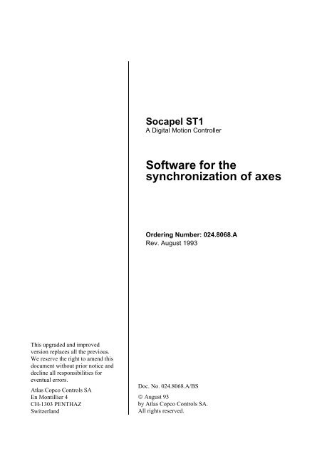
Socapel ST1A Digital Motion Controller<strong>S<strong>of</strong>tware</strong> <strong>for</strong> <strong>the</strong><strong>synchronization</strong> <strong>of</strong> <strong>axes</strong>Ordering Number: 024.8068.ARev. August 1993This upgraded and improvedversion replaces all <strong>the</strong> previous.We reserve <strong>the</strong> right to amend thisdocument without prior notice anddecline all responsibilities <strong>for</strong>eventual errors.Atlas Copco Controls SAEn Montillier 4CH-1303 PENTHAZSwitzerlandDoc. No. 024.8068.A/BS© August 93by Atlas Copco Controls SA.All rights reserved.
SOCAPEL SA SOFTWARE FOR SYNCHRONIZATION OF AXES 024.8068.ACONTENTS1. INTRODUCTION ................................................................................................................. 82. HARDWARE........................................................................................................................ 92.1 MICROPROCESSOR .......................................................................................... 92.2 PROGRAM MEMORY.......................................................................................... 92.3 PARAMETER MEMORY.................................................................................... 112.4 CYCLE TIME...................................................................................................... 123. SOFTWARE DESCRIPTION............................................................................................. 133.1 PROGRAM......................................................................................................... 133.2 VARIABLES........................................................................................................ 153.3 PARAMETERS................................................................................................... 153.4 PRECISION FORMATS ..................................................................................... 164. TOOLS FOR PARAMETER SET UP AND COMMISSIONING......................................... 174.1 TEST DEVICE.................................................................................................... 174.2 USE OF A PERSONAL COMPUTER (PC) ........................................................ 174.3 SOFTWARE DOWNLOADING .......................................................................... 174.4 DOWNLOADING PROCEDURE........................................................................ 185. STATUS DISPLAYS .......................................................................................................... 235.1 PRINCIPLE......................................................................................................... 235.2 SIGNIFICANCE OF THE DECIMAL POINT....................................................... 235.3. STATUS CODES................................................................................................ 246. STATUS BYTES AND MASKS.......................................................................................... 256.1 GENERAL .......................................................................................................... 256.2 STATUS BITS .................................................................................................... 266.2.1 Status STATA ..................................................................................... 266.2.2 Status STATB ..................................................................................... 276.2.3 Status STATC..................................................................................... 286.2.4 Status STATD..................................................................................... 286.2.5 Status STATE ..................................................................................... 296.3 STATUS MASKS................................................................................................ 306.4 RESET OF STATUS BITS ................................................................................. 312
SOCAPEL SA SOFTWARE FOR SYNCHRONIZATION OF AXES 024.8068.A7. DESCRIPTION OF BASIC ................................................................................................ 327.1 GENERAL .......................................................................................................... 327.2 EEPROM............................................................................................................ 327.2.1 Parameter CLECOM........................................................................... 327.2.2 Parameter VSOFT .............................................................................. 327.3 PARAMETERS FOR POSITION FEEDBACK ................................................... 337.3.1 Parameter CURES.............................................................................. 337.3.2 Parameters KVIRB.............................................................................. 347.3.3 Parameter NPPOL.............................................................................. 347.3.4 Parameter NVERN.............................................................................. 347.4 MOTOR PARAMETERS .................................................................................... 357.4.1 Motor File Libraries ............................................................................. 357.4.2 Parameter CDEPHA ........................................................................... 357.4.3 Parameter KTINV................................................................................ 357.4.4 Parameter KIGLIN .............................................................................. 367.4.5 Parameter IMAGNN............................................................................ 367.4.6 Parameter VITN.................................................................................. 377.4.7 Parameter VITMAX............................................................................. 377.5 POSITION CONTROLLER................................................................................. 387.5.1 Feed-<strong>for</strong>ward Commands ................................................................... 387.5.2 Position Controller............................................................................... 397.5.3 PI Speed Controller............................................................................. 407.5.4 Parameter KPOS ................................................................................ 417.5.5 Parameter KVIT .................................................................................. 417.5.6 Parameter KTEGR.............................................................................. 417.5.7 Parameter INERT ............................................................................... 427.5.8 Parameter FVISC................................................................................ 427.5.9 Parameter FSEC................................................................................. 427.5.10 Parameter FEXT................................................................................. 437.5.11 Parameter DPOMA............................................................................. 437.5.12 Parameter SEUIL1.............................................................................. 447.5.13 Parameter COUMA............................................................................. 447.5.14 Parameter COULIM ............................................................................ 447.6 STATUS MASKS................................................................................................ 453
SOCAPEL SA SOFTWARE FOR SYNCHRONIZATION OF AXES 024.8068.A7.7 PARAMETERS FOR THE TEST DEVICE ......................................................... 457.7.1 General ............................................................................................... 457.7.2 Parameters CADBIN........................................................................... 457.7.3 Parameters CADMA1 ......................................................................... 457.7.4 Parameters CADMA2 ......................................................................... 477.8 ABSOLUTE POSITION ...................................................................................... 477.8.1 General ............................................................................................... 477.8.2 Parameter PHIL1 ................................................................................ 477.8.3 Parameter PHIL2 ................................................................................ 478. REFERENCE GENERATOR............................................................................................. 488.1 GENERAL .......................................................................................................... 488.2 PRINCIPLE......................................................................................................... 488.3 PRINCIPLE......................................................................................................... 518.4 INTERNAL REFERENCE GENERATOR........................................................... 528.4.1 Control and Monitoring <strong>of</strong> Machine Movements ................................. 528.4.2 Units.................................................................................................... 548.4.3 Parameters CKA................................................................................. 548.4.4 Parameter CKV................................................................................... 558.4.5 Speed and Acceleration Modulation ................................................... 568.4.6 Parameter CVP................................................................................... 578.4.7 Parameter CVS................................................................................... 578.4.8 Parameters CA1 ................................................................................. 578.4.9 Parameter ASTOP.............................................................................. 588.4.10 Parameters MRATE............................................................................ 588.4.11 Parameter RATE................................................................................. 588.4.12 Program Position Units ....................................................................... 598.4.13 Parameters CKR................................................................................. 598.5 LINK WITH MASTER SHAFT............................................................................. 618.5.1 Principle .............................................................................................. 618.5.2 Parameters CKS................................................................................. 628.5.3 OEI...................................................................................................... 638.5.4 Parameter FILTEI ............................................................................... 648.5.5 Parameter ACCLIM............................................................................. 648.5.6 Parameter PISTEI............................................................................... 658.5.7 Parameter NIMPEI.............................................................................. 658.5.8 OM/OS................................................................................................ 668.5.9 OM/OS................................................................................................ 664
SOCAPEL SA SOFTWARE FOR SYNCHRONIZATION OF AXES 024.8068.A8.5.10 "Second resolver" Connection ............................................................ 678.6 SUMMATION AND SYNCHRONIZING.............................................................. 688.6.1 Adder and Integrator........................................................................... 688.6.2 Parameter CSCAN.............................................................................. 698.6.3 Parameters CPCORC......................................................................... 698.7 SWITCHING THE SYNCHRONIZING FUNCTION............................................ 708.7.1 Synchronizing ..................................................................................... 708.7.2 Desynchronizing ................................................................................. 728.7.3 Synchronizing and Phase-following.................................................... 738.7.4 Desynchronizing with Stop ................................................................. 748.8 PERIODICITY..................................................................................................... 758.8.1 Periodic Mode..................................................................................... 758.8.2 Pseudo-periodic Mode........................................................................ 768.8.4 Parameters PERIMC .......................................................................... 768.8.5 Parameter ZMPERS ........................................................................... 778.8.6 Parameter ZMPERM........................................................................... 778.9 CALCULATION EXAMPLE ................................................................................ 788.10 SYNCHRONIZATION PRECISION.................................................................... 818.11 REFERENCE TRANSDUCER ........................................................................... 828.11.1 Principle .............................................................................................. 828.11.2 Parameter COMOS ............................................................................ 838.12 POTENTIOMETER INPUT................................................................................. 848.12.1 Principle .............................................................................................. 848.12.2 Parameter OFPOT.............................................................................. 868.12.3 Parameter FILTPOT ........................................................................... 868.12.4 Parameter COEPOT........................................................................... 868.12.5 Parameter ZMPOT ............................................................................. 878.13. MISCELLANEOUS PARAMETERS ................................................................... 878.13.1 Parameter TIMTOP ............................................................................ 878.14 TRANSFERRING PARAMETERS ..................................................................... 889. DESCRIPTION OF SOME VARIABLES............................................................................ 899.1 GENERAL .......................................................................................................... 899.2 BASE VARIABLES ............................................................................................. 899.3 PSEUDO-PARAMETERS .................................................................................. 9010. EXECUTABLE INSTRUCTIONS....................................................................................... 9110.1 GENERAL .......................................................................................................... 915
SOCAPEL SA SOFTWARE FOR SYNCHRONIZATION OF AXES 024.8068.A10.2 INSTRUCTIONS MODIFYING THE PARAMETERS ......................................... 9110.2.1 Instruction SETPAR............................................................................ 9110.2.2 Instruction SETVAR............................................................................ 9210.2.3 Instruction SETOUT............................................................................ 9210.2.4 Instruction SPWARN........................................................................... 9310.2.5 Instruction SAVE................................................................................. 9310.3 READ INSTRUCTIONS..................................................................................................... 9410.3.1 Instruction ASKVAR............................................................................ 9410.3.2 Instruction ASKPAR............................................................................ 9410.3.3 Instruction ASKPRG ........................................................................... 9410.3.4 Instruction ASKIN................................................................................ 9510.3.5 Instruction ASKNXT............................................................................ 9510.3.6 Instruction ASKPOS............................................................................ 9510.3.7 Instruction ASKACT............................................................................ 9610.3.8 Instruction ASKABS............................................................................ 9610.3.9 Instruction ASKTOR ........................................................................... 9610.4 INSTRUCTIONS CONCERNING THE STATUS ............................................... 9710.4.1 Instruction NOOP................................................................................ 9710.4.2 Instruction ASKSTB ............................................................................ 9710.4.3 Instruction ASKSTC............................................................................ 9710.4.4 Instruction RESSTS............................................................................ 9810.5 INSTRUCTIONS CONTROLLING THE POWER STAGE ................................. 9810.5.1 Instruction PWROFF........................................................................... 9810.5.2 Instruction PWRRES........................................................................... 9810.5.3 Instructions PWRONS ........................................................................ 9910.5.4 Instruction PWRONR.......................................................................... 9910.6 INITIALIZATION INSTRUCTIONS ................................................................... 10010.6.1 Instruction INIPM .............................................................................. 10010.6.2 Instruction INIPS............................................................................... 10010.6.3 Instruction ALISU.............................................................................. 10110.6.4 Instruction ALIPOS ........................................................................... 10110.6.5 Instruction INIABS............................................................................. 10210.6.6 Instruction UPGRAD......................................................................... 10210.6.7 Instruction EQUPOS......................................................................... 10210.6.8 Instruction RESPOS ......................................................................... 1036
SOCAPEL SA SOFTWARE FOR SYNCHRONIZATION OF AXES 024.8068.A10.7 "MOVE" INSTRUCTIONS ................................................................................ 10310.7.1 General In<strong>for</strong>mation .......................................................................... 10310.7.2 Instruction START ............................................................................ 10410.7.3 Instruction STOP .............................................................................. 10410.7.4 Instructions EAMOV ......................................................................... 10410.7.5 Instructions ERMOV ......................................................................... 10510.7.6 Instructions ERUN ............................................................................ 10610.7.7 Instructions ESRUN.......................................................................... 10610.7.8 Instruction ESPOS............................................................................ 10710.7.9 Instructions ERPOS.......................................................................... 10710.7.10 Instruction ETOP .............................................................................. 10810.8 TORQUE CONTROL AND LIMITATION.......................................................... 10810.8.1 Instruction LIMTOR........................................................................... 10810.8.2 Instruction RESTOR ......................................................................... 10810.9 SOFTWARE DOWNLOADING ........................................................................ 10910.9.1 Instruction INIPGM ........................................................................... 10910.9.2. Instruction LDPGM ........................................................................... 10910.9.3. Instruction FILL ................................................................................. 11010.9.4. Instruction CHKSUM......................................................................... 11010.9.5. Instruction REBOOT ......................................................................... 111INDEX........................................................................................................................................ 1127
SOCAPEL SA SOFTWARE FOR SYNCHRONIZATION OF AXES 024.8068.A1. INTRODUCTIONIn addition to <strong>the</strong> power stage, <strong>the</strong> ST1 digital motion controller comprises a microprocessorbasedcontrol unit. It <strong>the</strong>re<strong>for</strong>e requires <strong>the</strong> s<strong>of</strong>tware described in <strong>the</strong> present manual.Whe<strong>the</strong>r delivered with <strong>the</strong> ST1 motion controller or on a separate non-volatile EPROMmemory board (or any o<strong>the</strong>r support), <strong>the</strong> present s<strong>of</strong>tware remains <strong>the</strong> exclusive property <strong>of</strong>Socapel SA, Penthaz, Switzerland. Copyright law prohibits <strong>the</strong> copying <strong>of</strong> this s<strong>of</strong>tware, evenpartially, by whatever method, without <strong>the</strong> written consent <strong>of</strong> <strong>the</strong> Owner. It is equallyprohibited to disassemble <strong>the</strong> s<strong>of</strong>tware content.By purchasing <strong>the</strong> ST1 digital motion controller, <strong>the</strong> User receives <strong>the</strong> right to employ <strong>the</strong>s<strong>of</strong>tware <strong>for</strong> its intended purpose.8
SOCAPEL SA SOFTWARE FOR SYNCHRONIZATION OF AXES 024.8068.A2. HARDWARE2.1 MICROPROCESSORThe ST1 digital motion controller uses <strong>the</strong> TMS 320C15 microprocessor manufactured byTexas Instruments. This processor is particularly well adapted <strong>for</strong> fast numerical handling <strong>of</strong>analog signals.2.2 PROGRAM MEMORYThe ST1 operating s<strong>of</strong>tware is stored in a non-volatile EPROM memory marked with <strong>the</strong>following in<strong>for</strong>mation :- The version number : V0001, V0002 etc.- The check-sum.- The programming date <strong>of</strong> <strong>the</strong> component.Each new edition <strong>of</strong> <strong>the</strong> s<strong>of</strong>tware has a separate version number, even when only minorchanges have been implemented. The version number is also stored in <strong>the</strong> memory as <strong>the</strong>VSOFT parameter.The program memory is mounted in a socket permitting replacement. To avoid damaging <strong>the</strong>chip, we recommend <strong>the</strong> use <strong>of</strong> an extraction tool (<strong>for</strong> example : Bernstein 2-601).Figure 2.1 shows <strong>the</strong> location and positioning <strong>of</strong> <strong>the</strong> memory. Also shown is bridge S4, whichhas <strong>the</strong> following function :- Pins 1 and 2 shorted : Memory size 8 or 16 kbytes (standard).- Pins 2 and 3 shorted : Memory size 32 kbytes (option).Note : All ST1 digital motion controllers shipped be<strong>for</strong>e mid-1990 were fitted with TMS32010 microprocessors. All s<strong>of</strong>tware versions are compatible with both processor types,except those with version number V0500, which require <strong>the</strong> TMS 320C15. If necessary, <strong>the</strong>processor may be exchanged : please consult your supplier.The s<strong>of</strong>tware can also be downloaded : refer to <strong>the</strong> correspon-ding documentation.When <strong>the</strong> ST1 is fitted with <strong>the</strong> s<strong>of</strong>tware-downloading option, <strong>the</strong> program memory provides<strong>for</strong> a boot program.(See § 4.3.)9
SOCAPEL SA SOFTWARE FOR SYNCHRONIZATION OF AXES 024.8068.AParameter memoryProgram memoryaS3S4321 32111param. memoryX2804 - EEPROMX2864 - EEPROMS32-32-3S41-22-3Parameter memoryProgram memory321S2321S3S5param. memoryS3S5b321S412311X2804 - EEPROMX2864 - EEPROMX28264 - EEPROM2-31-21-22-31-21-2Figure 2.1 : Location <strong>of</strong> program and parameter memories.The drawing shows <strong>the</strong> lower part <strong>of</strong> <strong>the</strong> R-board which is located on <strong>the</strong>right-hand side <strong>of</strong> <strong>the</strong> ST1.a) Equipment delivered up to 1991 (part numbers 024.77xx and024.77xx.A)b) Equipment delivered as from 1991 (part numbers 024.77xx.B andlater)10
SOCAPEL SA SOFTWARE FOR SYNCHRONIZATION OF AXES 024.8068.A2.3 PARAMETER MEMORYChapter 3.3 <strong>of</strong> this manual defines <strong>the</strong> notion <strong>of</strong> "parameter" in general, and <strong>the</strong> notion <strong>of</strong>"user's initial values" in particular. In <strong>the</strong> standard version, parameters are stored in anelectrically erasable/programmable memory (EEPROM type XICOR X2804 or X2864 orequivalent). For <strong>the</strong> downloaded-s<strong>of</strong>tware version, only a XICOR X2804 EEPROM (orequivalent)may be used.As <strong>for</strong> <strong>the</strong> program memory, <strong>the</strong> parameter memory is mounted in a socket. The sameprecautions should be taken in case <strong>of</strong> any exchange. Figure 2.1 shows <strong>the</strong> location andpositioning <strong>of</strong> this memory, and <strong>the</strong> correct insertion method <strong>for</strong> memories fitted with 24 or 28pins :- 28 pins : X2864 or X28256 EEPROM (standard),- 24 pins : X2804 EEPROM (exceptions).Positioning <strong>of</strong> mini-bridge S3 and S5 depends on <strong>the</strong> memory type, as shown in Figure 2.1.11
SOCAPEL SA SOFTWARE FOR SYNCHRONIZATION OF AXES 024.8068.A2.4 CYCLE TIMEThe internal oscillator <strong>of</strong> <strong>the</strong> microprocessor produces a clock signal whose frequency isdetermined by a crystal with an accuracy <strong>of</strong> ± 100 ppm.A PAL (programmable array logic) counter circuit determines <strong>the</strong> cycle time independentlyfrom <strong>the</strong> s<strong>of</strong>tware. This time is set at exactly 1/3 millisecond <strong>for</strong> <strong>the</strong> standard-version ST1.Certain s<strong>of</strong>tware versions may require different cycle times. The PAL circuit is <strong>the</strong>re<strong>for</strong>emounted on a socket to allow later exchange. Figure 2.2 shows <strong>the</strong> location as well as <strong>the</strong>installation method. To distinguish between versions, <strong>the</strong> PAL chip bears a label which mayread, <strong>for</strong> example, "333V4", which is <strong>the</strong> cycle time in microseconds, and <strong>the</strong> versionnumber.11Figure 2.2 : Location <strong>of</strong> <strong>the</strong> PAL circuit.The drawing shows <strong>the</strong> upper part <strong>of</strong> <strong>the</strong> R-board (located to right-handside <strong>of</strong> ST1), with PAL circuit (1) .12
SOCAPEL SA SOFTWARE FOR SYNCHRONIZATION OF AXES 024.8068.A3. SOFTWARE DESCRIPTION3.1 PROGRAMDue to <strong>the</strong> numerical regulator algorithm used in <strong>the</strong> microprocessor, <strong>the</strong> ST1 digital motioncontroller can be adapted to very varied applications by simply exchanging <strong>the</strong> s<strong>of</strong>tware. Thes<strong>of</strong>tware is structured by functions, to facilitate <strong>the</strong> creation <strong>of</strong> new application-dependentversions as required.Figure 3.1 : Functional blocks.Shown are <strong>the</strong> ST1 s<strong>of</strong>tware (left) and hardware (right), as well as <strong>the</strong> linkboard and test unit.13
SOCAPEL SA SOFTWARE FOR SYNCHRONIZATION OF AXES 024.8068.AThe most important functions <strong>of</strong> <strong>the</strong> basic s<strong>of</strong>tware are :- The start-up sequence.- Handling <strong>of</strong> variables and parameters.- Fault monitoring.- Measurement <strong>of</strong> <strong>the</strong> absolute position and <strong>the</strong> speed <strong>of</strong> <strong>the</strong> motor, using <strong>the</strong> resolver.- Axis control.- Current distribution to three-phase synchronous motor.- Output <strong>of</strong> variables through a test card.Added to this are special application-dependent functions such as :- Absolute positioning using a dual resolver (allows overriding limit switches in certaincases).- Control <strong>of</strong> three-phase induction motors with magnetizing current reduction, whichpermits speeds up to four times <strong>the</strong> nominal speed.- Serial communication with a host computer, allowing interactive dialog anddownloading <strong>of</strong> parameters.- Generation <strong>of</strong> acceleration and deceleration ramps, <strong>for</strong> motor speed-control or pointto-pointmovements.- Mutual synchronizing <strong>of</strong> <strong>axes</strong>, or synchronizing <strong>of</strong> one axis in relation to a referenceaxis.14
SOCAPEL SA SOFTWARE FOR SYNCHRONIZATION OF AXES 024.8068.A3.2 VARIABLESVariables are numerical magnitudes, whose value at any instant depends on <strong>the</strong> s<strong>of</strong>tware,<strong>the</strong> initialization parameters, <strong>the</strong> interpretation <strong>of</strong> external events, and running <strong>of</strong> <strong>the</strong> process.Except <strong>for</strong> a few exceptions, <strong>the</strong> variables <strong>of</strong> <strong>the</strong> ST1 digital motion controller are stored in<strong>the</strong> volatile memory (RAM), internal to <strong>the</strong> microprocessor. They respond to a specificaddress bus whose address ranges from 0 to 255 (hexa : 0...FF). (The TMS 320C10microprocessor limits this range to 143 (hexa : 8F).3.3 PARAMETERSParameters are numerical magnitudes with values defined by <strong>the</strong> user. They influence <strong>the</strong>initialization process as well as <strong>the</strong> effect <strong>of</strong> <strong>the</strong> s<strong>of</strong>tware and <strong>the</strong> associated variables. Theirvalue may be modified by <strong>the</strong> user or by <strong>the</strong> command host at any time, including duringoperation.The ST1 digital motion controller distinguishes between <strong>the</strong> following values <strong>for</strong> eachparameter :- The "default value", as defined by <strong>the</strong> firmware;- The user's "initial value", as defined by <strong>the</strong> user and stored in <strong>the</strong> parameter memory;- The "current value" which is <strong>the</strong> only one used in <strong>the</strong> calculation by <strong>the</strong> s<strong>of</strong>tware; thisvalue is stored in a volatile memory (RAM) - <strong>the</strong> so-called 'working storage'. Its islocated at address 52 to 255 (hexa : 34 ... FF) <strong>of</strong> <strong>the</strong> main address bus.During each start-up as well as after a reset command, <strong>the</strong> current value <strong>of</strong> each parameteris determined as follows :- If <strong>the</strong> parameter memory is in place, and if <strong>the</strong> compatibility codes correspond, <strong>the</strong>user's stored values are valid. The seven-segment status display on <strong>the</strong> ST1 indicatesan "8".- In <strong>the</strong> opposite case (and particularly if <strong>the</strong> ST1 is new or if <strong>the</strong> EEPROM is missing),<strong>the</strong> default values are valid. The status display will indicate a "9".Comment :If <strong>the</strong> ST1 digital motion controller detects a fault, <strong>the</strong> status displaymay indicate ano<strong>the</strong>r code. See paragraph 5.3.Subsequently, <strong>the</strong> current value may be changed :- By <strong>the</strong> user, using a programming terminal or a personal computer + test unit;- By <strong>the</strong> host computer, during downloading through <strong>the</strong> serial link;- By <strong>the</strong> built-in sequencer (if using <strong>the</strong> LIO link board).The current values <strong>of</strong> all parameters in <strong>the</strong> parameter memory can be transferred at anytime, under one condition : <strong>the</strong> corresponding memory must be <strong>of</strong> <strong>the</strong> standard type(EEPROM). It is thus possible to define new initial values.The saving procedure starts with <strong>the</strong> "SAVE" command from <strong>the</strong> user or from a hostcomputer at <strong>the</strong> end <strong>of</strong> a remote loading sequence. Saving takes a maximum <strong>of</strong> eightseconds. For certain s<strong>of</strong>tware versions, bit 3 <strong>of</strong> status STATC indicates <strong>the</strong> beginning and<strong>the</strong> end <strong>of</strong> <strong>the</strong> procedure. See paragraph 6.2.3.15
SOCAPEL SA SOFTWARE FOR SYNCHRONIZATION OF AXES 024.8068.A3.4 PRECISION FORMATSThe ST1 microprocessor processes all values (whe<strong>the</strong>r variables or parameters) in fixedpoint,16-bit <strong>for</strong>mat.Certain values are processed with double (or even triple) precision. The variable or <strong>the</strong>parameter is <strong>the</strong>n represented by two (or three) words <strong>of</strong> 16 bits, hence extends over 32 (or48) bits. In this case <strong>the</strong> suffix "A" indicates <strong>the</strong> least significant word <strong>of</strong> <strong>the</strong> variable or <strong>the</strong>parameter considered; <strong>the</strong> suffixes "B" and "C" indicate more significant words in <strong>the</strong>command.Examples :VIREF = + 1,890,071,254 (hexa : 70A8,32D6)gives VIREFB = 28,840 (hexa:70A8)VIREFA = 13,014 (hexa : 32D6)PHIRE = -164,831,062,250 (hexa: FFD9,9F4D,95EA)gives PHIREC = - 39 (hexa : FFD9)PHIREB = 40,781 (hexa : 9F4D)PHIREA = 38,378 (hexa : 95EA)The "ST1-EXPERT", which is a PC-DOS based s<strong>of</strong>tware <strong>for</strong> commissioning <strong>of</strong> ST1 digitalmotion controllers, is able to work using ei<strong>the</strong>r decimal, hexadecimal or binary <strong>for</strong>m asrequired. The "Microscribe" terminal only knows about hexa-decimal numbers.16
SOCAPEL SA SOFTWARE FOR SYNCHRONIZATION OF AXES 024.8068.A4. TOOLS FOR PARAMETER SET UP AND COMMISSIONING4.1 TEST DEVICEThe characteristic <strong>of</strong> every numerical controller is its ability to handle data by transferring itfrom one memory location to ano<strong>the</strong>r. The data is <strong>the</strong>re<strong>for</strong>e inaccessible without <strong>the</strong> addition<strong>of</strong> supplementary hardware.In <strong>the</strong> case <strong>of</strong> <strong>the</strong> ST1 digital motion controller, this hardware is contained on a special testdevice which is used when <strong>the</strong> equipment is being set up or tested. The device permits directaccess to any byte (8 bits) handled by <strong>the</strong> microprocessor. It also links two analog values <strong>for</strong>oscilloscope display. The choice <strong>of</strong> byte or analog value is made by entering parameters asdescribed in paragraph 7.7.The test device also includes a serial RS232 link <strong>for</strong> connection to a personal computer (PC)or a programming terminal.4.2 USE OF A PERSONAL COMPUTER (PC)The MS-DOS compatible ST1-EXPERT s<strong>of</strong>tware includes features <strong>for</strong> linking a personalcomputer (PC) to a ST1 digital motion controller. Please read manual No. 024.8038 "ST1-EXPERT" <strong>for</strong> fur<strong>the</strong>r details.4.3 SOFTWARE DOWNLOADINGStandard ST1 digital motion controller is fitted with an EPROM which supports <strong>the</strong>appropriate s<strong>of</strong>tware (see § 3.1).As an option, it can be fitted with a s<strong>of</strong>tware-download facility. This provides <strong>for</strong> a betterinterchargeability in applications where different s<strong>of</strong>twares are to be used. <strong>S<strong>of</strong>tware</strong>-updatesare also simpler to implement.Upon delivery (and unless o<strong>the</strong>rwise stated), no downloaded s<strong>of</strong>tware is stored. The ST1runs a "boot" program which provides <strong>for</strong> <strong>the</strong> following functions :- Operating system and fault detection :The standard operating system <strong>of</strong> ST1 is running, with its fault detection, display andstatus. But <strong>the</strong>se are no functions <strong>for</strong> controlling <strong>the</strong> motor. The power stage cannot beenabled. The resolver interface is not running.- Serial link :Two interfaces <strong>for</strong> serial link are available :- over <strong>the</strong> test device, using <strong>the</strong> fixed length protocole (see document 024.8020"Link board LIO"). This part is to be used with a PC and "The Socasin EXPERT"s<strong>of</strong>tware.- over <strong>the</strong> link board, using following protocoles :- LS and LIO boards : fixed frame protocole (see document024.8020 "Link board LIO")- LPO board : PAM-ring protocole- LA boards : no interface available.17
SOCAPEL SA SOFTWARE FOR SYNCHRONIZATION OF AXES 024.8068.A- Specifical status bits :§ 5.3 gives all necessary in<strong>for</strong>mations.- Reduced and specific instruction set :Only those standard instructions specific to <strong>the</strong> reading and <strong>the</strong> setting <strong>of</strong>variables parameters and similar values are available. They are descripted in §10.1 through 10.4, whereas <strong>the</strong>ir availability in <strong>the</strong> boot s<strong>of</strong>tware is mentioned.Fur<strong>the</strong>r instructions which are specific to <strong>the</strong> downloading procedure areavailable, but only in <strong>the</strong> boot s<strong>of</strong>tware. They are descripted in § 10.9.4.4 DOWNLOADING PROCEDUREThis paragraph describes <strong>the</strong> s<strong>of</strong>tware download procedure, which has to be implementedinto <strong>the</strong> host command when ST1's link board is <strong>of</strong> LS or LIO type.In such cases, <strong>the</strong> communication <strong>for</strong> downloading protocole is always ST1'sprotocole", as described in document 024.8020 "Link board LIO"."fixed frameShould <strong>the</strong> ST1 be fitted with an LS link board, (and only in that case), <strong>the</strong>n mostdownloaded s<strong>of</strong>twares use ST1's "optimal length protocole", as described in document024.8012 "Link boards LS". The host command must <strong>the</strong>n be able to use both protocoles.18
SOCAPEL SA SOFTWARE FOR SYNCHRONIZATION OF AXES 024.8068.AAll downloadable firmwares are available as PC-DOS files (JEDEC <strong>for</strong>mat).The first line <strong>of</strong> JED file start with '0' or 'K' and <strong>the</strong> first 13 characters are not available. Then<strong>the</strong> <strong>for</strong>mat <strong>of</strong> Jedec"Comand" is made <strong>of</strong> 5 characters strings:x a b c dwhere : x = string type'0' or 'K' = skip 13 characters'9' = new address pointer'B' = data'7' or '8' =end <strong>of</strong> line':' = end <strong>of</strong> filea b c d = address pointer or data(16 bits, in hexadecimal code)The corresponding "Jedec Comand" and ST1 instructions are listed below:Ubon reading on "9abcd" string, <strong>the</strong> host has to send a "INIPGM" instruction to <strong>the</strong> ST1 (6bytes) as follows.Instr.CodeD a t a b y t e saddress INIPGM 0a b c d checksumUpon reading on "B a b c d" string, <strong>the</strong> host has to send a "LDPGM" instruction to <strong>the</strong> ST1 (6bytes) as follows :Instr.CodeD a t a b y t e saddress LDPGM 0a b c d checksumThe whole procedure is shown in <strong>the</strong> following flow-chart :19
SOCAPEL SA SOFTWARE FOR SYNCHRONIZATION OF AXES 024.8068.Ainitialise:SUM = 0OR = 0LINE = 0CHAR = 0incrementLINE by 1Read string(5 characters)X = '7' or '8'yesX = '0' or 'K'yesincrementCHAR by 13incrementCHAR by 5X = '9'yesSend to ST1an INIPGMX = '8'yesSend to ST1a LDPGMSend to ST1an ASKSTCX = ':'noerroryesbit 2 ° 0incrementADR by 2ADR > 512noincrementSUM by ab + cd20
SOCAPEL SA SOFTWARE FOR SYNCHRONIZATION OF AXES 024.8068.Ayessend to ST1a FILL 0send to ST1an ASKSTCbit 1 ° 0yesnoSend to ST1a CHKSUM SUMASKSTCbit 0 ° 0yesnoSend to ST1a REBOOTWait 1 secondInitialize link to ST1(LS board with o<strong>the</strong>r protocol)send to ST1an ASKPAR CLECOMST1answersyesCLECOM ° 1yesdonnloading completednonoerror (no link)error(s<strong>of</strong>tware notloaded)Figure 4.1 : Dounloading flow-chart21
SOCAPEL SA SOFTWARE FOR SYNCHRONIZATION OF AXES 024.8068.ABe<strong>for</strong>e downloading a s<strong>of</strong>tware to a ST1, this one must be running <strong>the</strong> "boot" s<strong>of</strong>tware. If not,<strong>the</strong> previously loaded s<strong>of</strong>tware has to be "killed", as follows :- initialise link to ST1 (with <strong>the</strong> proper protocole)- send to ST1 a "SETOUT >4055 0" instruction (Desable Download program)- send to ST1 a "SETPAR >23 0" instruction (Reset ST1)- wait <strong>for</strong> about 1 second. (Until ST1 Display "6")- initialise link to ST1 (with fixed frame protocol)It is also possible to activate <strong>the</strong> "boot" s<strong>of</strong>tware momentarily by pushing <strong>the</strong> "reset" buttonon test device while pressing <strong>the</strong> ST1 "reset" button. In that case, <strong>the</strong> s<strong>of</strong>tware runs its "boot"s<strong>of</strong>tware and displays a "6".22
SOCAPEL SA SOFTWARE FOR SYNCHRONIZATION OF AXES 024.8068.A5. STATUS DISPLAYS5.1 PRINCIPLEThe ST1 digital motion controller has a 7-segment LED status display on <strong>the</strong> front panel. Thisdisplay indicates in coded <strong>for</strong>m <strong>the</strong> last important event which occurred in <strong>the</strong> unit.This may be a matter <strong>of</strong> normal events (<strong>for</strong> example : enabling <strong>the</strong> power stage) or abnormalevents (<strong>for</strong> example : lack <strong>of</strong> auxiliary supply). Paragraph 5.3 lists <strong>the</strong> significance <strong>of</strong> eachcode.5.2 SIGNIFICANCE OF THE DECIMAL POINTIn addition to <strong>the</strong> coded display, <strong>the</strong> decimal point indicates status <strong>of</strong> <strong>the</strong> ST1 digital motioncontroller :- Decimal point extinguished : This signals that <strong>the</strong> equipment is not being fed withcorrect auxiliary supply (+ 5 VDC shorted or out <strong>of</strong> spec.).- Decimal point dimmed : Indicates that <strong>the</strong> equipment is being fed correctly, but that <strong>the</strong>s<strong>of</strong>tware does not function correctly (watch-dog error in <strong>the</strong> microprocessor).- Decimal point strongly lit : The equipment is fed correctly and <strong>the</strong> s<strong>of</strong>tware isfunctioning.In case <strong>of</strong> doubt, it is possible to make a distinction between <strong>the</strong> last two states by resetting<strong>the</strong> microprocessor :- Press <strong>the</strong> "RESET" button on <strong>the</strong> ST1 digital motion controller. The decimal pointshould be dimmed.- Release <strong>the</strong> "RESET" button. The brightness <strong>of</strong> <strong>the</strong> decimal point should increasesignificantly.23
SOCAPEL SA SOFTWARE FOR SYNCHRONIZATION OF AXES 024.8068.A5.3. STATUS CODESThe following codes are valid only when <strong>the</strong> decimal point is lit strongly."0" : The power stage has been disabled as a result <strong>of</strong> an external command andnot because <strong>of</strong> a fault."1" : The power stage has been enabled."6" : No firmware available; boot program is running (§ 4.3)."7" : Reboot and load <strong>the</strong> downloading s<strong>of</strong>tware"8" : Unit initialized, with <strong>the</strong> transfer <strong>of</strong> <strong>the</strong> user's initial values as current values<strong>of</strong> <strong>the</strong> parameters."9" : Unit initialized, with <strong>the</strong> transfer <strong>of</strong> <strong>the</strong> default values as current values <strong>of</strong> <strong>the</strong>parameters."A" :"C" :The power stage has been disabled as a result <strong>of</strong> a failure in <strong>the</strong> 48 VDCauxiliary supply supply.The power stage has been disabled as a result <strong>of</strong> a fault in <strong>the</strong> resolverfeedback circuit."d" : The power stage has been disabled as a result <strong>of</strong> an internal failure :- Auxiliary supplies + 5 V, + 15 V, - 15 V are out <strong>of</strong>tolerances.- Defective s<strong>of</strong>tware ("watch-dog" has been triggered)."E" : Parameter memory or jumpers not ok (§2.3)."H" : A checksum error has been seen after downloading a s<strong>of</strong>tware (§4.4)."L" :"M" :"o" :"P" :"r" :"S" :The power stage has been disabled as a result <strong>of</strong> exceeding parameterprogrammed limit positions.Internal hardware error.The power stage has been disabled by <strong>the</strong> variables STATC/STATD as setby <strong>the</strong> mask parameter CMASKU. See fur<strong>the</strong>r explanations in paragraph 6.3.The power stage has been disabled as a result <strong>of</strong> an over voltage conditionin <strong>the</strong> DC bus.Fault test completed successfully.The power stage has been blocked as a result <strong>of</strong> an overload or a shortcondition."U" : Memory overrun while downloading a s<strong>of</strong>tware (§ 4.4).O<strong>the</strong>r codes may appear, depending on <strong>the</strong> configuration options (particularly, <strong>the</strong> "s<strong>of</strong>twaredownloading" option). Refer to <strong>the</strong> relevant documentation.24
SOCAPEL SA SOFTWARE FOR SYNCHRONIZATION OF AXES 024.8068.A6. STATUS BYTES AND MASKS6.1 GENERALThe general condition <strong>of</strong> <strong>the</strong> ST1 operation can be observed by looking at four status byteswhich summarizes <strong>the</strong> conditions <strong>of</strong> <strong>the</strong> unit. Each piece <strong>of</strong> in<strong>for</strong>mation is assigned to one bit.The fault indicating bits are latched. These bits can trigger an interrupt in <strong>the</strong> fault handlingroutine <strong>of</strong> <strong>the</strong> ST1 digital motion controller. Those bits which simply indicates a state orcondition are not latched.The status bytes are called STATA, STATB, STATC and STATD. Figure 6.1 shows <strong>the</strong>numeration <strong>of</strong> <strong>the</strong> corresponding bits, bytes and words.bit #MSB7 6 5 4 3 2 1 0 7 6 5 4 3 2 1 0LSBbyteSTATASTATBSTAT1, address 128 (hexa : 80)bit #7 6 5 4 3 2 1 0 7 6 5 4 3 2 1 0byteSTATCSTATDSTAT2, address 129 (hexa : 81)Figure 6.1 : Status bytes.Those status bits which are significent while <strong>the</strong> boot program is running, or whiledownloading a s<strong>of</strong>tware are marked with a " * " . (see also § 4.4).25
SOCAPEL SA SOFTWARE FOR SYNCHRONIZATION OF AXES 024.8068.A6.2 STATUS BITS6.2.1 Status STATAThe STATA byte provides essential in<strong>for</strong>mation on <strong>the</strong> status <strong>of</strong> <strong>the</strong> ST1 digital motioncontroller and its s<strong>of</strong>tware.Bit 7 (latched) signals that <strong>the</strong> power stage has been disabled as a result <strong>of</strong> a fault.Normal disabling will not have any effect on this bit.Bit 6 (latched) in<strong>for</strong>ms that <strong>the</strong>re has been a change in <strong>the</strong> two bytes <strong>of</strong> <strong>the</strong> STATCand STATD status as a function <strong>of</strong> <strong>the</strong> mask MASKS. See paragraph 6.3.Bit 5 indicates whe<strong>the</strong>r <strong>the</strong> real position is less than ("1") or greater than ("0") <strong>the</strong>value set by <strong>the</strong> instruction SPWARN (see paragraph 10.2.4).Bit 4 signals that <strong>the</strong> position lag (variable DPOS) is greater than ("1") or less than("0") <strong>the</strong> value set by <strong>the</strong> parameter SEUIL1. It provides an overall functional control <strong>of</strong><strong>the</strong> axis, allowing <strong>the</strong> disclosure <strong>of</strong> any occurrence <strong>of</strong> excessive friction or a cablerupture, <strong>for</strong> example. It is resumed under <strong>the</strong> memorized <strong>for</strong>mat in STATD. In certainversions <strong>of</strong> <strong>the</strong> s<strong>of</strong>tware, velocity lag DVIT is monitored instead <strong>of</strong> <strong>the</strong> position lag ifparameter KTEGR = 32,768 (hexa : 8000).Bit 3 signals that <strong>the</strong> move requested by an instruction ERMOV, ERUN, START,STOP etc. is in progress. The bit is set to "1" when one <strong>of</strong> <strong>the</strong> above instructions isreceived and returns to "0" when <strong>the</strong> corresponding move is finished.Bit 2 is used by those s<strong>of</strong>tware versions which require computation time between <strong>the</strong>receipt <strong>of</strong> a move order and <strong>the</strong> execution <strong>of</strong> it. It is set to "1" when <strong>the</strong> computation isfinished, which means that a START order will follow immediately. It returns to "0" assoon as <strong>the</strong> move has startedBits 1 and 0 give in<strong>for</strong>mation about <strong>the</strong> status <strong>of</strong> <strong>the</strong> motor speed during <strong>the</strong> execution<strong>of</strong> a move <strong>of</strong> <strong>the</strong> axis :Bit 1 Bit 0 Meaning0 0 Stop (reference speed zero)0 1 Acceleration1 1 At speed (reference speed not zero)1 0 Deceleration26
SOCAPEL SA SOFTWARE FOR SYNCHRONIZATION OF AXES 024.8068.APAMOVSTARTPAMOVSTARTSETVELSETA1EAMOVPRUNSTARTVbit 5Tw
SOCAPEL SA SOFTWARE FOR SYNCHRONIZATION OF AXES 024.8068.A6.2.3 Status STATCThe effects <strong>of</strong> <strong>the</strong> bits <strong>of</strong> variable STATC depend on <strong>the</strong> masks, as described inparagraph 6.3. The listing which accompanies every s<strong>of</strong>tware version, shows all bitshaving really a meaning. All <strong>the</strong> o<strong>the</strong>r bits remain set to "0".* Bit 7 (latched) indicates that a not valid instruction code has been received.* Bit 6 (latched) indicates that implausible instruction code or data has beenreceived.* Bit 5 (latched) indicates a firmware fault and must always be "0". Should it beset to "1" <strong>the</strong>n please call immediately your supplier.* Bit 4 (latched) indicates after powering up or resetting that <strong>the</strong> present linkcard is not compatible with <strong>the</strong> present s<strong>of</strong>tware version, or that <strong>the</strong> card ismissing. Afterwards, it indicates a serial link transmission failure.Bit 3 is "1" as long as <strong>the</strong> SAVE routine is in progress, which saves all parameteractual values into <strong>the</strong> EEPROM parameter memory. It returns to "0" as soon as savinghas been completed.* Bit 2 indicates that <strong>the</strong> master shaft has overrun <strong>the</strong> limit <strong>of</strong> one period, or that<strong>the</strong> zero track <strong>of</strong> an incremental encoder has been detected. Refer toparagraphs 8.5.6 and 8.8.1.* Bit 1 reproduces <strong>the</strong> state <strong>of</strong> input No. 2 <strong>of</strong> some link cards. If <strong>the</strong> entry is open(no current, zero voltage), <strong>the</strong> bit is at 1. If <strong>the</strong> entry is fed, it is at 0.While downloading a s<strong>of</strong>tware (§ 4.4 and § 10.9.3) bit 1 indicates that <strong>the</strong>EEPROM memory filling in under way.* Bit 0 depends on <strong>the</strong> state <strong>of</strong> input No. 1 <strong>of</strong> some link cards, as bit 1.While downloading a s<strong>of</strong>tware (§ 4.4 and § 10.0.4), bit 0 indicates that <strong>the</strong>checksum computation is under way.6.2.4 Status STATDThe effects <strong>of</strong> <strong>the</strong> bits <strong>of</strong> variable STATD depend on <strong>the</strong> masks as STATC. The listingwhich accompanies every s<strong>of</strong>tware version, shows all bits having really a meaning. Allo<strong>the</strong>r bits remain set to "0".* Bit 7 (latched) indicates excessive motor temperature, or that <strong>the</strong>corresponding input <strong>of</strong> <strong>the</strong> ST1 digital motion controller is not connected.Bit 6 (latched) indicates that <strong>the</strong> internal overheating protection circuitry is active andreducing <strong>the</strong> current to <strong>the</strong> motor.Bit 5 (latched) is a latched copy <strong>of</strong> bit 4 <strong>of</strong> STATA.Bit 4 (latched) indicates that <strong>the</strong> real position has exceeded (even if only briefly) <strong>the</strong>limits set by parameters PHIL1/PHIL2. Refer to paragraph 7.8.Bit 3 (latched) indicates that <strong>the</strong> ST1 digital motion controller has initiated a STOPprocedure.Bit 2 (latched) indicates a failure <strong>of</strong> <strong>the</strong> optional board.28
SOCAPEL SA SOFTWARE FOR SYNCHRONIZATION OF AXES 024.8068.A* Bit 1 (latched) is used to determine if <strong>the</strong> microprocessorhas been reinitialized("RESET") or not. The validity <strong>of</strong> <strong>the</strong> position measurement (number <strong>of</strong> turns)and <strong>the</strong> o<strong>the</strong>r variables depends on it. After each restart <strong>of</strong> <strong>the</strong> microprocessor,this bit is worth 1. It is put back to 0 by one <strong>of</strong> <strong>the</strong> initialization commands <strong>of</strong>status described in paragraph 6.4, and particularly when <strong>the</strong> power stage isenabled. Then, it can only go back to 1 with a new restart <strong>of</strong> <strong>the</strong> microprocessor.Bit 0 indicates if <strong>the</strong> power stage is enabled ("0"), or disabled ("1").6.2.5 Status STATEBit 7 indicates that a motor speed has exceeded <strong>the</strong> limit set by <strong>the</strong> parameterVITMAX . 1.12529
SOCAPEL SA SOFTWARE FOR SYNCHRONIZATION OF AXES 024.8068.A6.3 STATUS MASKSThe bits <strong>of</strong> variables STATC and STATD may be used to automatically start one <strong>of</strong> <strong>the</strong>emergency procedures described below. The masks are <strong>the</strong> parameters matching <strong>the</strong>seprocedures to each bit.In determining <strong>the</strong> value <strong>of</strong> <strong>the</strong> masks, it is necessary to recall that <strong>the</strong> STATC and STATDbytes are collected in <strong>the</strong> <strong>for</strong>m <strong>of</strong> only one word. Bits 0 to 7 correspond to STATD, and bits 8to 15 correspond to bits 0 to 7 <strong>of</strong> STATC (see Figure 6.1).For every mask, a logical "AND" combination is executed bit to bit. If <strong>the</strong> result is not zero,<strong>the</strong> corresponding procedure is started.Example :If bit 7 <strong>of</strong> <strong>the</strong> mask is "1", any excessive motor temperature (bit 7 <strong>of</strong>STATD) starts <strong>the</strong> desired procedure. If <strong>the</strong> bit is "0", <strong>the</strong> motortemperature does not have any effect.Three masks are available, each one corresponding to a specific procedure :- CMASKU selects those bits which, when <strong>the</strong>y are "1", cause a disabling <strong>of</strong> <strong>the</strong> powerstage (no current to <strong>the</strong> motor).Address :124 (hexa : 7C).Default value : 128 (hexa : 80)- CMASKA selects those bits which, when <strong>the</strong>y are "1", produce a controlleddeceleration <strong>of</strong> <strong>the</strong> motor, that means a "STOP" (reference speed <strong>of</strong> <strong>the</strong> motor atzero). This mask is only active in s<strong>of</strong>tware versions which support point to point moveor <strong>the</strong> speed control by serial communication.With <strong>the</strong> LIO link board and s<strong>of</strong>tware versions including sequencer functions, thisCMASKA status initiates no STOP. It opens instead <strong>the</strong> output OUT7. Seecorresponding manual.Address :125 (hexa : 7D).Default value : 0.- CMASKS selects those bits which, in case <strong>of</strong> a change <strong>of</strong> status, set bit 6 <strong>of</strong> STATA to"1". Thus, in case <strong>of</strong> a serial communication, <strong>the</strong> command host is quickly in<strong>for</strong>medabout <strong>the</strong> occurrence <strong>of</strong> a change. The host can <strong>the</strong>n inquire about <strong>the</strong> new status <strong>of</strong><strong>the</strong> variables STATC and STATD.Address :Default value :126 (hexa : 7E).61,680 (hexa : F0F0).As <strong>the</strong> boot program is running, only CMASKS (with its default value) mask is active.30
SOCAPEL SA SOFTWARE FOR SYNCHRONIZATION OF AXES 024.8068.A6.4 RESET OF STATUS BITSThe latched bits are automatically set to "0" at powering up and after <strong>the</strong> microprocessor hasbeen reset (with <strong>the</strong> exception <strong>of</strong> bit 1 <strong>of</strong> STATD, which is set to "1"). They only return to "1"if <strong>the</strong> corresponding fault is detected.The serial link or <strong>the</strong> sequencer function, if available, make it possible to reset all status bitsusing one <strong>of</strong> <strong>the</strong> RESSTS, PWRRES, PWRONS, PWRONI or PWRONR instructions. Seealso <strong>the</strong> corresponding paragraphs <strong>of</strong> chapter 10.As <strong>the</strong> boot program is running, only instruction RESSTS is available <strong>for</strong> resetting <strong>the</strong> statusbits.31
SOCAPEL SA SOFTWARE FOR SYNCHRONIZATION OF AXES 024.8068.A7. DESCRIPTION OF BASIC PARAMETERS7.1 GENERALThe per<strong>for</strong>mance <strong>of</strong> <strong>the</strong> ST1 digital motion controller may be enhanced in <strong>the</strong> future. It is<strong>the</strong>re<strong>for</strong>e wise to maintain a certain versatility in <strong>the</strong> number <strong>of</strong> <strong>the</strong> parameters.Those described in this document concern most <strong>of</strong> <strong>the</strong> s<strong>of</strong>tware versions in use today. Forsome particular functions additional parameters may be introduced; see <strong>the</strong> correspondingnotices. In any case <strong>the</strong>re is only one valid reference : <strong>the</strong> listing which describes eachversion.When a user's initial value is not determined, it is essential to keep <strong>the</strong> default value plannedby <strong>the</strong> creator <strong>of</strong> <strong>the</strong> s<strong>of</strong>tware. All default values are indicated in <strong>the</strong> listing.7.2 EEPROM MEMORY CONTROL PARAMETERS7.2.1 Parameter CLECOMThis is a compatibility key. The parameter determines <strong>the</strong> validity <strong>of</strong> <strong>the</strong> default valuesor <strong>of</strong> <strong>the</strong> user's initial values, depending on <strong>the</strong> s<strong>of</strong>tware introduced. If <strong>the</strong> value <strong>of</strong>CLECOM contained in <strong>the</strong> parameter memory (user's initial value) is <strong>the</strong> same as <strong>the</strong>one contained in <strong>the</strong> program memory (default value), all user's initial values areadmitted as current values. In <strong>the</strong> opposite case, <strong>the</strong> default values are kept. See alsoparagraph 3.3.Address : 52 (hexa : 34).7.2.2 Parameter VSOFTThis parameter shows which s<strong>of</strong>tware version is active.Address : 55 (hexa : 37).32
SOCAPEL SA SOFTWARE FOR SYNCHRONIZATION OF AXES 024.8068.A7.3 PARAMETERS FOR POSITION FEEDBACK7.3.1 Parameter CURESThis parameter defines <strong>the</strong> resolver excitation voltage. The value is only input as astarting value. The real voltage value is automatically determined by <strong>the</strong> controller(variable URES). The CURES parameter value is only used <strong>for</strong> resolver faultsupervision. The value depends on <strong>the</strong> type <strong>of</strong> resolver used.Manufacturer Type CURESHarowe 21 BRCX-310-F-8 1,280 (hexa : 500)Harowe 21 BRCX-310-H-7 1,536 (hexa : 600)Harowe 11 BRCX-300-A-95 256 (hexa : 100)PrécilecPrécilecThomsonThomsonSagemSagemSagemSagem26V 21 RN45PE-0926V 20 RN45PE-0326 SM 19 RX 452 C 0/F/0026 TM 11 RX 4a ... k22 RX 04 02 04 (A)21 RX 34 02 0121 RX 34 03 0815 RX 37 01 181,280 (hexa : 500)1,280 (hexa : 500)1,536 (hexa : 600)256 (hexa : 100)1,280 (hexa : 500)1,280 (hexa : 500)1,280 (hexa : 500)1,280 (hexa : 500)When using o<strong>the</strong>r resolver types proceed as follows :- Turn on ST1 supplies.- Read <strong>the</strong> value <strong>of</strong> <strong>the</strong> URES variable.- Introduce and save this value as <strong>the</strong> CURES parameter.- A difference not greater than 500 (hexa : 200) between <strong>the</strong> values URES andCURES is allowed.Address : 56 (hexa : 38).Default value : 1,536 (hexa : 600).33
SOCAPEL SA SOFTWARE FOR SYNCHRONIZATION OF AXES 024.8068.A7.3.2 Parameters KVIRB, KVIRIN, KSIN and KSIINVThese parameters depend on <strong>the</strong> resolver secondary voltages. For <strong>the</strong> types listedabove, <strong>the</strong> default values should not be modified, namely :AddressDefault valueKVIRB 57 (hexa : 39) 19,700 (hexa : 4CF4)KVIRIN 58 (hexa : 3A) 6,954 (hexa : 1B2A)KSIN 59 (hexa : 3B) 3,277 (hexa : CCD)KSIINV 60 (hexa : 3C) 5,120 (hexa : 1400)7.3.3 Parameter NPPOLSee paragraph 7.4.1 : Motor file libraries. This parameter defines <strong>the</strong> relation between<strong>the</strong> number <strong>of</strong> motor poles and <strong>the</strong> number <strong>of</strong> resolver poles.Example : Resolver having 2 poles (1-speed), and a motor with 8poles : NPPOL = 4.Address :61 (hexa : 3D).Default value : 4.7.3.4 Parameter NVERNThis parameter is used when dual resolvers are used to obtain an absolute positioningsystem. In this case, NVERN is equal to <strong>the</strong> length <strong>of</strong> absolute measurement <strong>of</strong> <strong>the</strong>position, expressed in number <strong>of</strong> turns.Example :For 2 resolvers (1-speed) connected with one ratio reducer256/255, <strong>the</strong> measurement is absolute over 256 turns.Then NVERN = 256 (hexa : 100).Address :62 (hexa : 3E).Default value : 1.34
SOCAPEL SA SOFTWARE FOR SYNCHRONIZATION OF AXES 024.8068.A7.4 MOTOR PARAMETERS7.4.1 Motor File LibrariesFor synchronous and induction motor types which have been used successfully withST1 digital motion controllers, all corresponding parameters have already beendetermined and checked. They were brought into MS-DOS compatible files andlibraries. Read manual No. 024.8038, "ST1-EXPERT", <strong>for</strong> fur<strong>the</strong>r details.7.4.2 Parameter CDEPHAThis parameter defines <strong>the</strong> phase relationship between <strong>the</strong> zero <strong>of</strong> <strong>the</strong> resolver andzero <strong>of</strong> <strong>the</strong> motor (if synchronous). The resolver should usually be installed accordingto a procedure described in <strong>the</strong> operation manual. CDEPHA is <strong>the</strong>n set to 0. Whensystem constraints prevent <strong>the</strong> resolver from being ideally aligned to <strong>the</strong> motor poles,<strong>the</strong> angular difference can be compensated by <strong>the</strong> CDEPHA parameter.Address : 68 (hexa : 44).Default value : 0.7.4.3 Parameter KTINVSee paragraph 7.4.1 : Motor file libraries. This parameter defines <strong>the</strong> torque constant<strong>of</strong> <strong>the</strong> motor winding. The value 4,096 (hexa : 1000) corresponds to a motor whichsupplies a torque <strong>of</strong> 1 Nm when <strong>the</strong> current is 1A (peak value) or 0.71 A RMSIf <strong>the</strong> motor supplier specifies <strong>the</strong> value K T [Nm/A] using RMS value <strong>of</strong> <strong>the</strong> current,KTINV is calculated as follows :KTINV = 2 . 4,096 / K TExample :If K T = 0.76 Nm/A RMS , KTINV = 7,622 (hexa : 1DC6).For induction (asynchronous) motor <strong>the</strong> K T value is generally not available. Proceed<strong>the</strong>n as follows :1) Nominal torque : M n [Nm] =PWn[ ]n [ rpm] ⋅30 πn2) "Active" nominal current : Ia RMS [A] = In RMS . cos ϕ3) Constant torque : K T =MIan[ Nm][ A]RMSAddress : 69 (hexa : 45).Default value : 8,192 (hexa : 2000).35
SOCAPEL SA SOFTWARE FOR SYNCHRONIZATION OF AXES 024.8068.A7.4.4 Parameter KIGLINSee paragraph 7.4.1 : Motor file libraries. If <strong>the</strong> motor is <strong>of</strong> induction type(asynchronous), this parameter defines <strong>the</strong> ratio between <strong>the</strong> slip frequency and <strong>the</strong>actual current at nominal speed.If sN is <strong>the</strong> nominal slip [revs/second], IN <strong>the</strong> nominal current [in A RMS ] and cos j <strong>the</strong>power factor, <strong>the</strong>n KIGLIN is given by :KIGLIN =p⋅sN⋅494.3IN ⋅cosϕIt is recommended to increase <strong>the</strong> calculated value by 10%.Example : A 4-pole motor (p = 2), with I N = 11.4 A RMS , cos ϕ =0.85, v N = 1,700 rpm and fn = 60 Hz.The slip s N = (60/2) - (1,700/60) = 1.667 revs/s.KIGLIN = (2 . 1.667 . 494.3 / (11.4 . 0.85)= 170 (hexa : A8).If <strong>the</strong> motor is <strong>of</strong> synchronous type, KIGLIN must be 0.Address : 73 (hexa : 49).Default value : 0.7.4.5 Parameter IMAGNN (induction motor only)See paragraph 7.4.1 : Motor file libraries. This parameter defines <strong>the</strong> nominalmagnetizing (reactive) current rating If IN is <strong>the</strong> nominal current <strong>of</strong> <strong>the</strong> motorexpressed in A RMS , and cos j its nominal power factor, <strong>the</strong>n <strong>the</strong> value <strong>of</strong> IMAGNN isobtained by :IMAGNN = 128 . 2 . I N . sin ϕNote :Example :Due to <strong>the</strong> effect <strong>of</strong> saturation a 10 to50% lower value may be considered.A motor with I N = 17 A RMS and cos ϕ= 0.85. The following is obtained :sin ϕ = 1 - cos 2 ϕ = 0.527IMAGNN = 1,621 (hexa : 655)Address : 74 (hexa : 4A).Default value : 384 (hexa : 180)36
SOCAPEL SA SOFTWARE FOR SYNCHRONIZATION OF AXES 024.8068.A7.4.6 Parameter VITN (induction motor only)See paragraph 7.4.1 : Motor file libraries. This parameter defines <strong>the</strong> highest (base)speed <strong>of</strong> <strong>the</strong> motor at rated nominal magnetizing current. The ST1 digital motioncontroller provides rated magnetizing current up to that speed. For higher speeds <strong>the</strong>ST1 digital motion controller automatically reduces <strong>the</strong> magnetizing current.The value <strong>of</strong> VITN is given by :VITN = base speed [rpm] . 256 / 704Example :The base speed is 1400 rpm.VITN = 1,400 . 256 / 704 = 509 =(hexa : 1FD).Address :75 (hexa : 4B).Default value : 1,092 (hexa : 444).7.4.7 Parameter VITMAXSee paragraph 7.4.1 : Motor file libraries. This parameter defines <strong>the</strong> maximum speed<strong>of</strong> <strong>the</strong> motor as determined by <strong>the</strong> motor manufacturer. The ST1 digital motioncontroller limits <strong>the</strong> frequency in such a way that this speed is never exceeded, nomatter which reference speed has been set. Bit 7 <strong>of</strong> STATUS E is set, if <strong>the</strong> speed islimited. However, a lower value may be used if required.The value <strong>of</strong> VITMAX is given by :VITMAX = maximum speed [rpm] . 256 / 704Address :76 (hexa : 4C).Default value : 1,092 (hexa : 444).37
SOCAPEL SA SOFTWARE FOR SYNCHRONIZATION OF AXES 024.8068.A7.5 POSITION CONTROLLER PARAMETERS7.5.1 Feed-<strong>for</strong>ward CommandsIn all conventional controllers a torque command can only be produced when avelocity or position lag exists. Usually, an integrator is used to eliminate this lag.However, this method is ineffective <strong>for</strong> dynamic speed changes and producesdisturbing overshoots.Never<strong>the</strong>less, <strong>the</strong> torque required from <strong>the</strong> motor to produce a given degree <strong>of</strong>movement can largely be estimated : even where <strong>the</strong> inertia load varies, torque canusually be estimated to within 20 percent. Friction loads (dry or sliding), or <strong>the</strong>influence <strong>of</strong> gravity (on vertical <strong>axes</strong>), can be calculated or approximated empirically,allowing <strong>the</strong> load to be "modeled".Modeling consists in knowing <strong>the</strong> desired position, speed and acceleration at anymoment, and <strong>the</strong>n calculating <strong>the</strong> required motor torque <strong>for</strong> this model. As it is appliedas an open loop, this feed-<strong>for</strong>ward control method never produces instabilities.Of course, a real system per<strong>for</strong>ms differently from <strong>the</strong> model. But <strong>the</strong> positioncontroller only has to correct <strong>for</strong> <strong>the</strong> difference between <strong>the</strong> <strong>the</strong>oretical torque and <strong>the</strong>actual system parameters. Since this difference is always <strong>the</strong> lesser value, positioningerror is reduced accordingly.In each application, <strong>the</strong> obvious aim is to model as accurately as possible, ei<strong>the</strong>r by<strong>the</strong>oretical calculations or testing. Only afterwards is control coefficient I determined. Inmany cases this coefficient will be zero.38
SOCAPEL SA SOFTWARE FOR SYNCHRONIZATION OF AXES 024.8068.A7.5.2 Position ControllerThe ST1 digital motor controller s<strong>of</strong>tware includes a PID position controller with feed<strong>for</strong>wardcommands. The position feedback is derived from a resolver mounted at <strong>the</strong>end <strong>of</strong> <strong>the</strong> motor shaft. No tachometer is required. The regulation parameters can beadjusted experimentally or can be premodeled as shown later.bit 41STATAPHI1DPOMA1500KTEGRS 1220SEUIL 1bit 5STATD2PHIRE+(RU)- •VIREF(RU/TU)VIR-2 -16 min.max. DPOS KPOS2 8+• 2 -16 max. DVIT KVIT- •min.2 8-++ +-minmaxCOCOU7FFF2 -16 (32767) +•+FVISC2 8RESTORCOUMALIMTORCOULIM+F0-FFFSECAR (RU/TU 2)INERT2 16 FEXTFigure 7.1 : PID position controller.The position and velocity feedbacks are provided through a resolver todigital converter (1). The set values come from <strong>the</strong> "host" command orfrom <strong>the</strong> internal velocity pr<strong>of</strong>ile generator (2). The position lag (DPOS)and <strong>the</strong> velocity lag (DVIT) are reversed compared to <strong>the</strong> usualconventions; a positive value corresponds to an advance.39
SOCAPEL SA SOFTWARE FOR SYNCHRONIZATION OF AXES 024.8068.A7.5.3 PI Speed ControllerIn many s<strong>of</strong>tware versions, <strong>the</strong> PID position controller can be replaced with a PI speedcontroller by setting <strong>the</strong> KTEGR parameter to 32,768 (hexa : 8000). The motor speedis <strong>the</strong>n regulated independently <strong>of</strong> <strong>the</strong> position. Figure 7.2 shows this configuration.This feature is useful when only <strong>the</strong> speed <strong>of</strong> <strong>the</strong> axis is to be controlled and a largevelocity lag is expected, due to a torque limit <strong>for</strong> example. In this mode <strong>of</strong> operation <strong>the</strong>position controller normally adds up <strong>the</strong> entire lag, and cannot stop <strong>the</strong> motor be<strong>for</strong>ebringing it back to zero. With <strong>the</strong> PI controller this problem is eliminated.When operating in this mode, <strong>the</strong>re<strong>for</strong>e, it is <strong>the</strong> velocity lag (DVIT) that is checked.The KPOS parameter controls <strong>the</strong> integration constant <strong>of</strong> <strong>the</strong> speed loop and <strong>the</strong>DPOMA parameter controls <strong>the</strong> level <strong>of</strong> integration.bit 41STATA1min.16DPOMA 21500Smax.DPOSKPOS820SEUIL 1bit 5STATD2VIREF(RU/TU)VIR-+• 2 -16 min.max. DVIT KVIT2 8 •-+ + ++minmaxCOCOU>7FFF2 -16 (32767) +•+FVISC2 8RESTORCOUMALIMTORCOULIM+F0-FFFSECAR (RU/TU ) 2INERT2 16 FEXTFigure 7.2 : PI speed controller. Position lag DPOS has no effect.40
SOCAPEL SA SOFTWARE FOR SYNCHRONIZATION OF AXES 024.8068.A7.5.4 Parameter KPOSWhen <strong>the</strong> unit is operated as a position controller <strong>the</strong> KPOS term determines <strong>the</strong>proportional gain (block P). When operated as a speed control KTEGR is set to 32,768(hexa : 8000), and KPOS determines <strong>the</strong> integration constant (I) <strong>of</strong> <strong>the</strong> speedcontroller. In both cases, it influences directly <strong>the</strong> relation between <strong>the</strong> output torqueand <strong>the</strong> corresponding angular distance.The KPOS value should be positive between 1 and 32,767 (hexa : 1 ... 7FFF). WhenKPOS = 256 (hexa : 100), an angular distance or position error <strong>of</strong> 0.0123 radiansproduces a counter-torque <strong>of</strong> 1Nm.Please refer to application note AN 5 : "The speed and position controlling regulator"No. 024.8042 <strong>for</strong> <strong>the</strong> adjustment <strong>of</strong> this parameter.Address : 80 (hexa : 50).Default value : 48 (hexa : 30).7.5.5 Parameter KVITThis parameter determines <strong>the</strong> derivative gain (D) <strong>of</strong> <strong>the</strong> position controller, or <strong>the</strong>proportional gain (block P) <strong>of</strong> <strong>the</strong> speed controller. It is required to ensure <strong>the</strong> stability<strong>of</strong> <strong>the</strong> system.The KVIT value should be positive between 1 and 32,767 (hexa : 1 ... 7FFF). WithKVIT = 256 (hexa : 100), a velocity error <strong>of</strong> 2.30 rad/s produces a counter torque <strong>of</strong> 1Nm.Please refer to application note AN 5 : "The speed and position controlling regulator"No. 024.8042 <strong>for</strong> <strong>the</strong> adjustment <strong>of</strong> this parameter.Address : 81 (hexa : 51).Default value : 96 (hexa : 60).7.5.6 Parameter KTEGRThis parameter determines <strong>the</strong> integration constant <strong>of</strong> <strong>the</strong> position controller (I) when<strong>the</strong> amplifier is operated as a position control. It also serves as a choice whe<strong>the</strong>r <strong>the</strong>unit should operate as a position or velocity controller as explained in paragraph 7.5.3.When <strong>the</strong> position regulator is active, <strong>the</strong> KTEGR value should be positive between 0and 32,767 (hexa : 0 ... 7FFF).To select <strong>the</strong> speed regulator, set KTEGR = 32,768 (hexa : 8000).Please refer to application note AN 5 : "The speed and position controlling regulator"No. 024.8042 <strong>for</strong> <strong>the</strong> adjustment <strong>of</strong> this parameter.Address : 82 (hexa : 52).Default value : 0.41
SOCAPEL SA SOFTWARE FOR SYNCHRONIZATION OF AXES 024.8068.A7.5.7 Parameter INERTThis parameter indicates <strong>the</strong> total system inertia. It greatly reduces <strong>the</strong> second-orderlag due to <strong>the</strong> load inertia during <strong>the</strong> acceleration. If <strong>the</strong> total value <strong>of</strong> <strong>the</strong> load inertiaas seen by <strong>the</strong> motor shaft JT, expressed in kgm2, is known, <strong>the</strong> value is obtained by :INERT = 119,000 . J T .INERT should be positive or zero between 0 and 32,767 (hexa : 0 ... 7FFF).Example : If inertia J T = 0.012 kgm 2 , <strong>the</strong> following is obtained :INERT = 1,428 (hexa : 594).Please refer to application note AN 5 : "The speed and position controlling regulator"No. 024.8042 <strong>for</strong> <strong>the</strong> adjustment <strong>of</strong> this parameter.Address : 83 (hexa : 53).Default value : 0.7.5.8 Parameter FVISCThis parameter specifies <strong>the</strong> viscous damping constant. It allows a reduction <strong>of</strong> <strong>the</strong>first order error without introducing additional integration. FVISC should be positive orzero between 0 and 32,767 (hexa : 0 ... 7FFF).Please refer to application note AN 5 : "The speed and position controlling regulator"No. 024.8042 <strong>for</strong> <strong>the</strong> adjustment <strong>of</strong> this parameter.Address : 84 (hexa : 54).Default value : 0.7.5.9 Parameter FSECThis parameter compensates <strong>for</strong> static friction. It must be adjusted after FVISC hasbeen determined.It is without effect when <strong>the</strong> reference speed is zero and it produces a constant feed<strong>for</strong>ward torque, positive or negative, when <strong>the</strong> reference speed is not zero.FSEC should be a positive value between 0 and 32,767 (hexa : 0 ... 7FFF).Please refer to application note AN 5 : "The speed and position controlling regulator"No. 024.8042 <strong>for</strong> <strong>the</strong> adjustment <strong>of</strong> this parameter.Address : 85 (hexa : 55).Default value : 0.42
SOCAPEL SA SOFTWARE FOR SYNCHRONIZATION OF AXES 024.8068.A7.5.10 Parameter FEXTThis parameter allows <strong>for</strong> <strong>the</strong> compensation <strong>of</strong> loads that are overhauling or notcounterbalanced. It allows <strong>for</strong> a reduction <strong>of</strong> <strong>the</strong> position error when such a torque isapplied to <strong>the</strong> motor such as in <strong>the</strong> load <strong>of</strong> a vertical axis. FEXT can also becontinuously readjusted by a "host" command when a serial connection exists.FEXT can have any positive or negative value, except 32,768 (hexa : 8000). A valueFEXT = 128 (hexa : 80) compensates <strong>for</strong> a torque <strong>of</strong> 1 Nm.Please refer to application note AN 5 : "The speed and position controlling regulator"No. 024.8042 <strong>for</strong> <strong>the</strong> adjustment <strong>of</strong> this parameter.Address : 86 (hexa : 56).Default value : 0.7.5.11 Parameter DPOMAThis parameter defines <strong>the</strong> linearity limit <strong>for</strong> <strong>the</strong> position lag. When <strong>the</strong> value DPOS isless than DPOMA, <strong>the</strong> torque produced by <strong>the</strong> controller is a function <strong>of</strong> <strong>the</strong> lag.Beyond, it remains constant.The value <strong>of</strong> DPOMA is given by :DPOMA = 216 ⋅lag rad2 ⋅πmax[ ]= 2lag 16 max[deg]360When <strong>the</strong> position controller is disabled by KTEGR = 32,768 (hexa : 8000), DPOMA isused as limit <strong>for</strong> <strong>the</strong> integrator <strong>of</strong> <strong>the</strong> speed controller.The value <strong>of</strong> DPOMA is <strong>the</strong>n given by :DPOMA ==202 max. speed lag [ rad / s]⋅3000 2 ⋅π202 max. speed lag [deg/ s]⋅3000 2 ⋅πDPOMA should be positive between 1 and 32,767 (hexa : 1 ... 7FFF).Please refer to application note AN 5 : "The speed and position controlling regulator"No. 024.8042 <strong>for</strong> <strong>the</strong> adjustment <strong>of</strong> this parameter.Address : 87 (hexa : 57).Default value : 4,096 (hexa : 1000).This value corresponds to a lag <strong>of</strong> 0.39 [rad] or 0.0625 [rev], respectively 73.6 [rad/s]or 703 [rpm].43
SOCAPEL SA SOFTWARE FOR SYNCHRONIZATION OF AXES 024.8068.A7.5.12 Parameter SEUIL1This parameter determines <strong>the</strong> warning level <strong>for</strong> excessive lag (position-control mode)or excessive speed (speed-control mode) : KTEGR = 32,768 (hexa : 8000). Seeparagraphs 6.2.1 and 6.2.4 <strong>for</strong> descriptions <strong>of</strong> bit 4 <strong>of</strong> STATA and bit 5 <strong>of</strong> STATD.The value <strong>of</strong> SEUIL1 is expressed in <strong>the</strong> same way as DPOMA (described above).Please refer to application note AN 5 : "The speed and position controlling regulator"No. 024.8042 <strong>for</strong> <strong>the</strong> adjustment <strong>of</strong> this parameter.Address : 88 (hexa : 58).Default value : 2,048 (hexa : 800).This value corresponds to a lag <strong>of</strong> 0.20 [rad] or 0.0313 [rev], respectively 36.8 [rad/s]or 351 [rpm].7.5.13 Parameter COUMAThis parameter determines <strong>the</strong> maximum torque output <strong>of</strong> <strong>the</strong> drive system. The valuemay be set based on mechanical limitations, to prevent demagnetization <strong>of</strong> asynchronous motor, or to <strong>the</strong> maximum current which <strong>the</strong> ST1 can produce.The value <strong>of</strong> COUMA is given by :COUMA = max. torque [Nm] . 128COUMA shall be positive between 1 and 32,767 (hexa : 1 ... 7FFF).Please refer to application note AN 5 : "The speed and position controlling regulator"No. 024.8042 <strong>for</strong> <strong>the</strong> adjustment <strong>of</strong> this parameter.Address : 89 (hexa : 59).Default value : 512 (hexa : 800).This value corresponds to a max. torque <strong>of</strong> 4 Nm.Note : The default value <strong>of</strong> previousversions was 8,192 (hexa : 2000).7.5.14 Parameter COULIMThis parameter determines <strong>the</strong> level <strong>of</strong> <strong>the</strong> 2nd torque limit. This limit is activated by<strong>the</strong> instruction "LIMTOR".The value is expressed in <strong>the</strong> same way as COUMA.Address :90 (hexa : 5A).Default value : 0.44
SOCAPEL SA SOFTWARE FOR SYNCHRONIZATION OF AXES 024.8068.A7.6 STATUS MASKS CMASKU, CMASKA AND CMASKSThese parameters are explained in paragraph 6.3.7.7 PARAMETERS FOR THE TEST DEVICE7.7.1 GeneralThe functions <strong>of</strong> <strong>the</strong> test device are described in paragraph 4. This card allowsmeasuring <strong>of</strong> variables in digital (one byte <strong>of</strong> 8 bits) or analog <strong>for</strong>m (two outputs <strong>of</strong> ±10 V). The choice <strong>of</strong> variables as well as <strong>the</strong> scaling is determined by <strong>the</strong> parametersdescribed below. The default condition <strong>of</strong> <strong>the</strong> s<strong>of</strong>tware measuring <strong>the</strong>se variables isOFF. It is changed to ON by <strong>the</strong> parameter CMPBIN. It is recommended to deactivate<strong>the</strong> s<strong>of</strong>tware (that is, set CMPBIN = 0) after taking <strong>the</strong> measurements, to avoidoverloading <strong>the</strong> processor.7.7.2 Parameters CADBIN and CMPBINThe parameter CADBIN defines <strong>the</strong> address <strong>of</strong> <strong>the</strong> variable to be monitored digitally.Pins No. 0 to 7 <strong>of</strong> <strong>the</strong> device are <strong>for</strong> <strong>the</strong> eight bits <strong>of</strong> <strong>the</strong> chosen byte (pin No. 0 = lsb).The name and address <strong>of</strong> each variable are given in <strong>the</strong> listing which describes eachs<strong>of</strong>tware version. See also paragraph 9. The address extends from 0 to 255 (hexa : 0... FF).The parameter CMPBIN specifies if <strong>the</strong> byte monitored is <strong>the</strong> most significant or <strong>the</strong>least significant <strong>of</strong> <strong>the</strong> selected variable. In addition, a low level (0) completelydeactivates <strong>the</strong> test s<strong>of</strong>tware and <strong>the</strong> analog values are no longer available.CMPBIN = 0deactivatedCMPBIN = 16 (hexa : 10) : most significant byte (bits 8 ... 15)CMPBIN = 4,096 (hexa : 1000) : least significant byte (bits 0 ... 7)AddressDefault valueCADBIN 128 (hexa : 80) 128 (hexa : 80)CMPBIN 129 (hexa : 81) 0 (<strong>for</strong> byte STATA).7.7.3 Parameters CADMA1 and CMPMA1For enabling <strong>the</strong> test device see paragraph 7.7.1The parameter CADMA1 defines <strong>the</strong> address <strong>of</strong> <strong>the</strong> analog variable to be monitoredon pin A1 <strong>of</strong> <strong>the</strong> test device. The address is determined in <strong>the</strong> same way as <strong>the</strong>parameter CADBIN. In <strong>the</strong> case <strong>of</strong> variables with double or triple precision, onlyaccess to one (1) word is possible.45
SOCAPEL SA SOFTWARE FOR SYNCHRONIZATION OF AXES 024.8068.AThe parameter CMPMA1 defines a scale factor <strong>for</strong> <strong>the</strong> A1 analog output. Theconverter resolution is 8 bits corresponding to a resolution <strong>of</strong> 78.1 mV. The followingtable shows <strong>the</strong> value <strong>of</strong> CMPMA1 in accordance with <strong>the</strong> desired full scale andresolution.- 10 V ... + 10 V Resolution CMPMA1- 32,767 ... + 32,767 (hexa : 8001 ... 7FFF) 256 (hexa : 100) 16 (hexa : 10)- 2,047 ... + 2,047 (hexa : F801 ... 7FF) 16 (hexa : 10) 256 (hexa : 100)- 127 ... + 127 (hexa : FF81 ... 7F) 1 (hexa : 1) 4,096 (hexa : 1000)Intermediate values are allowed. The following relation binds <strong>the</strong> chosen variable, <strong>the</strong>parameter CMPMA1 and <strong>the</strong> output voltage :U OUT [V] = value [lsb] . CMPMA1 . 0.078 [V] / 4,096AddressDefault valueCADMA1 130 (hexa : 82) 53 (hexa : 35)CMPMA1 131 (hexa : 83) 256 (hexa : 100)These values correspond to <strong>the</strong> position lag DPOS, where + 10 V represents adeviation <strong>of</strong> 1/32 <strong>of</strong> a rotation (11.25°), with a resolution <strong>of</strong> 1/4096 <strong>of</strong> a revolution (5.3').The scale factors could be set according to <strong>the</strong> following table.speed referenceVIREFBaddress: 47(>2F)Position lagDPOSaddress: 53 (>35)torqueCOCOUaddress: 55 (>37)CMPMAi [t/min/V] CMPMAi [deg/V] CMPMAi [Nm/V]72 (>48) 2000 144 (>90) 2 82 (>52) 5144 (>90) 1000 288 (>120) 1 205 (> CD) 2288 (>120) 500 576 (>24) 0.5 410 (>19A) 1722 (>2D2) 200 1444 (>5A4) 0.2 820 (>334) 0.51444 (>5A4) 100 2888 (>B48) 0.1 1444 (>5A4) 0.246
SOCAPEL SA SOFTWARE FOR SYNCHRONIZATION OF AXES 024.8068.A7.7.4 Parameters CADMA2 and CMPMA2These parameters define <strong>the</strong> second variable measured in analog <strong>for</strong>m on pin A2 <strong>of</strong><strong>the</strong> test device. They are determined in <strong>the</strong> same way as <strong>the</strong> parameters CADMA1and CMPMA1.AddressDefault valueCADMA2 132 (hexa : 84) 41 (hexa : 29)CMPMA2 133 (hexa : 85) 2,048 (hexa : 800)These values correspond to <strong>the</strong> actual speed VIRB, where + 10 V represents a speed<strong>of</strong> approx. 700 rpm with a resolution <strong>of</strong> 2.7 rpm.7.8 ABSOLUTE POSITION LIMITS7.8.1 GeneralThe two parameters described below define <strong>the</strong> absolute position limit values. Whenone <strong>of</strong> <strong>the</strong>se values is exceeded, <strong>the</strong> power stage is disabled. See paragraph 6.2.4, bit4 <strong>of</strong> STATD.7.8.2 Parameter PHIL1This parameter determines <strong>the</strong> "left" limit <strong>for</strong> <strong>the</strong> absolute position. A position lowerthan <strong>the</strong> value <strong>of</strong> PHIL1 is considered as an error, except if parameter PHIL2 equals32,768 (hexa : 8000).The value <strong>of</strong> PHIL1 may be positive or negative. A value PHIL1 = 16 (hexa : 10)corresponds to one revolution.Address : 134 (hexa : 86).Default value : 32,768 (hexa : 8000).7.8.3 Parameter PHIL2This parameter determines <strong>the</strong> "right" limit <strong>for</strong> <strong>the</strong> absolute position. A position higherthan <strong>the</strong> value <strong>of</strong> PHIL2 is considered as an error. Setting parameter PHIL2 equals32,768 (hexa : 8000), disables both overtravel limits <strong>for</strong> continuous systems with noposition restriction.The value <strong>of</strong> PHIL2 may be positive or negative, however, it is necessary to verify thatPHIL2 > PHIL1. A value PHIL2 = 16 (hexa : 10) corresponds to 1 shaft revolution.Address : 135 (hexa : 87).Default value : 32,768 (hexa : 8000).This value disables both overtravel limits PHIL1 and PHIL2.47
SOCAPEL SA SOFTWARE FOR SYNCHRONIZATION OF AXES 024.8068.A8. REFERENCE GENERATOR8.1 GENERALThe general block diagram (Figure 8.1) serves as <strong>the</strong> basis <strong>for</strong> <strong>the</strong> present section. Figure8.2 is a reduced <strong>for</strong>mat.The in<strong>for</strong>mation contained in this paragraph is general in<strong>for</strong>mation covering all s<strong>of</strong>twareversions. For reasons <strong>of</strong> per<strong>for</strong>mance and speed, <strong>the</strong> various s<strong>of</strong>tware versions contain onlythose functions that are required <strong>for</strong> <strong>the</strong> particular application.The term "host computer" employed hereafter refers to equipment external to <strong>the</strong> ST1 andused <strong>for</strong> commanding <strong>the</strong> motion controller. The term "sequencer" refers to a s<strong>of</strong>twarefunction per<strong>for</strong>med by <strong>the</strong> LIO board (if installed) - this board can be used with, or in place <strong>of</strong>,<strong>the</strong> host. Each instruction is executed by <strong>the</strong> ST1 within a particular sampling cycle ("TU").8.2 PRINCIPLEThe motor can be slaved to various references provided by <strong>the</strong> internal reference generatoror a "master shaft". These two references are switched in turn, or summed to make a singlereference.48
49Figure 8.1 : Reference computer+ 10VMaster shaft valueOEI, OS or2nd resolverRATEXRATEVALPOTVMUSKV x KACVPCVSDATA RUNLINK WITH MASTER SHAFTINSTRUCTIONPMASTVMASTMRATE / SRATEFLRATE0%CKS CKM CKMS CRANSKS KM KMS RANSMASTER -SLAVECONVERSIONItalic-written mnemo: parameters ( i.e. : CKV)Normal- written mnemo: variables ( i.e. : KV)INTERNAL REFERENCE GENERATORAMUSPMUSVMUS100%KRATEabsolute valuePALINS signed00CSCANNBSCANCPCORPCORXADDERFLSUIVCA1,2XA1,2ACCELERATIONMODULATION+x KAX+++CKVKVXMOTION MANAGERACGES VGESx KA0COCOUINTEGRATORINTVKACC1,2VPALGESVITINTEGRATORPABSREFERENCE TRANSDUCERCOMOStowardo<strong>the</strong>r ST1sARB / ARAVIREF+ PHIRESOCAPEL SA SOFTWARE FOR SYNCHRONIZATION OF AXES 024.8068.A
SOCAPEL SA SOFTWARE FOR SYNCHRONIZATION OF AXES 024.8068.AInternal referencegeneratorAddertoward position andvelocity controllerMastershaftLink andconversionReferencetransducertoward o<strong>the</strong>rST1sFigure 8.2 : General Block Diagram (reduced <strong>for</strong>mat)The INTERNAL REFERENCE GENERATOR (abbreviated hereafter to "IRG") trans<strong>for</strong>msinstructions from <strong>the</strong> host or <strong>the</strong> sequencer into a string <strong>of</strong> speed and position commands;<strong>the</strong>se are updated at each sampling cycle (TU). The generator is described in paragraph 8.4below.The link with <strong>the</strong> MASTER SHAFT supplies speed and position commands updated at eachsampling period. These commands undergo unit conversion. The link is described inparagraph 8.5.The ADDER combines <strong>the</strong> above two commands according to set modes contained in <strong>the</strong>host and sequencer instructions. This process is described in paragraph 8.6. This summationresults in :- a reference speed (variable "VIREF"),- a corresponding reference position (variable "PHIRE"),- a reference acceleration (variable "AR").The above three components are sent to <strong>the</strong> position/speed controller, in <strong>the</strong> same units asthose taken at <strong>the</strong> motor by <strong>the</strong> resolver. The position measurement is an absolute valuewithin <strong>the</strong> given period.The REFERENCE TRANSDUCER (see paragraph 8.11) feeds <strong>the</strong> references to <strong>the</strong> o<strong>the</strong>r<strong>axes</strong>.50
SOCAPEL SA SOFTWARE FOR SYNCHRONIZATION OF AXES 024.8068.A8.3 PRINCIPLETime baseThe ST1 sampling period is also used as <strong>the</strong> basic time unit (TU); it is set by a crystal with anaccuracy <strong>of</strong> ± 100 ppm. For most s<strong>of</strong>tware versions, this period equates to 1/3,000 sec. =333.3 µs, or a frequency <strong>of</strong> 3 kHz ± 0.3 Hz.Motor positionA one-speed resolver is normally employed, that is, having a single pole-pair. Thus <strong>the</strong>resolver period corresponds to one actual rotation <strong>of</strong> <strong>the</strong> motor. Hence <strong>the</strong> resolver unit (RU)is expressed as :1 RU = 2 -32 motor revs.If a higher number <strong>of</strong> poles is used, <strong>the</strong> motor rotation period is reduced accordingly.Example :Resolver with four pole-pairs : 1 RU = 2 -34 motor revs.Motor speedThe motor speed measurement is based on <strong>the</strong> two units defined above. For a resolverhaving a single pole-pair, <strong>the</strong> speed unit (RU/TU) is <strong>the</strong>re<strong>for</strong>e expressed as :1 RU/TU = 2 -32 motor revs . 3,000 rps = 4.39 . 10 -6 rad/s.The effect <strong>of</strong> crystal precision on speed is described in paragraph 8.10 within <strong>the</strong> context <strong>of</strong><strong>synchronization</strong> precision.Motor accelerationAcceleration measurement is obtained from <strong>the</strong> position and time units. The acceleration unit(RU/TU 2 ) is given by :1 RU/TU 2 = 2 -32 . 3,000 2 rp/s 2 = 13.2 . 10 -3 rad/s 2.51
SOCAPEL SA SOFTWARE FOR SYNCHRONIZATION OF AXES 024.8068.A8.4 INTERNAL REFERENCE GENERATORThe internal reference generator has two distinct functions :- control and monitor machine movements,- speed- and acceleration-changing (this function prepares data <strong>for</strong> <strong>the</strong> monitoringfunction).8.4.1 Control and Monitoring <strong>of</strong> Machine MovementsThe basic function <strong>of</strong> <strong>the</strong> internal reference generator consists in altering a continuousspeed reference over successive time units, while incorporating any instructionsreceived in <strong>the</strong> meantime, or any variables changing during <strong>the</strong> movement. This speedreference is <strong>the</strong> variable VGES. The corresponding acceleration reference is <strong>the</strong>variable ACGES.The function applies in two ways :- motion executed in terms <strong>of</strong> speed, that is, commanded by instructions <strong>of</strong> <strong>the</strong>"RUN" type (such as ERUN, SRUN etc.);- motion executed in terms <strong>of</strong> position, that is, commanded by instructions <strong>of</strong> <strong>the</strong>"MOV" or "POS" types (such as EMOV, RMOV, SPOS etc.).Motion executed in terms <strong>of</strong> speed (referred to hereafter as "RUN motion") :The speed changes from one value to ano<strong>the</strong>r (conditioned by <strong>the</strong> acceleration anddeceleration ramps), WITH NO ALLOWANCE <strong>for</strong> positioning, ei<strong>the</strong>r be<strong>for</strong>e or after <strong>the</strong>speed change.Instruction receivedVGESAccelerationFinal speedV initialV initialDecelerationtAccelerationFinal speedFigure 8.352
SOCAPEL SA SOFTWARE FOR SYNCHRONIZATION OF AXES 024.8068.AData :- Initial VGES value; current speed when instruction received;- VPAL (<strong>the</strong> terminal speed);- KACC1, KACC2 (acceleration values).Results :- VGES, ACCGES.Motion executed in terms <strong>of</strong> position (referred to hereafter as "MOV/POS motion") :The speed changes from an initial value to a NULL value, transiting through anintermediate speed but with integral speed control (thus motion occurs during <strong>the</strong>change).(intermediate) speed levelVGESInstruction receivedV pal.Figure 8.4Data :- Initial VGES value; current speed when instruction received;- VPAL (<strong>the</strong> terminal speed, or travel speed);- KACC1, KACC2 (acceleration values) :- PGES (distance to travel).Results :- VGES, ACCGES.53
SOCAPEL SA SOFTWARE FOR SYNCHRONIZATION OF AXES 024.8068.A8.4.2 UnitsThe internal units described above give excellent resolution <strong>for</strong> both speeds andaccelerations. They require <strong>the</strong> processing <strong>of</strong> a large number <strong>of</strong> data bits to cover <strong>the</strong>limit values, but this is not problematic <strong>for</strong> <strong>the</strong> ST1's microprocessor.In order to process a lower number <strong>of</strong> bits, thus increase processing speed, <strong>the</strong>internal reference generator works with its own system <strong>of</strong> units. Its position unit is <strong>the</strong>Generator Unit (GU). It employs <strong>the</strong> basic time unit (TU).GU's are converted into TU's using <strong>the</strong> parameters CKA and CKAINV, which arebinary coefficients. These coefficients also define <strong>the</strong> acceleration scale. Theparameter CKV defines <strong>the</strong> speed scale.8.4.3 Parameters CKA and CKAINVThe parameter CKA sets <strong>the</strong> scale factor <strong>for</strong> <strong>the</strong> acceleration. The choice is limited to<strong>the</strong> values in <strong>the</strong> table below.The parameter also allows <strong>the</strong> definition <strong>of</strong> <strong>the</strong> positive rotation direction <strong>of</strong> <strong>the</strong> motor.When this becomes apparent from <strong>the</strong> resolver, <strong>the</strong> positive direction corresponds tocounterclockwise rotation <strong>of</strong> <strong>the</strong> motor shaft ("ma<strong>the</strong>matical" definition).The parameter CKAINV is only an auxiliary parameter. It is also determined with <strong>the</strong>help <strong>of</strong> <strong>the</strong> following table.Acceleration [rad/s2] CKA CKAINVFull scale Resolution PositivedirectionNegative direction1,710 0.0527 4 - 4 (h : FFFC) 16,384 (h : 4000)3,420 0.1053 8 - 8 (h : FFF8) 8,192 (h : 2000)6,850 0.2107 16 (h : 10) - 16 (h : FFF0) 4,096 (h : 1000)13,700 0.4212 32 (h : 20) - 32 (h : FFE0) 2,048 (h : 800)27,400 0.843 64 (h : 40) - 64 (h : FFC0) 1,024 (h : 400)54,800 1.685 128 (h : 80) - 128 (h : FF80) 512 (h : 200)109,000 3.37 256 (h : 100) - 256 (h : FF00) 256 (h : 100)54
SOCAPEL SA SOFTWARE FOR SYNCHRONIZATION OF AXES 024.8068.AComments :- The acceleration values indicated are valid <strong>for</strong> a resolver with one pole pair("one-speed"). For o<strong>the</strong>r models, <strong>the</strong> desired acceleration should be multipliedby <strong>the</strong> number <strong>of</strong> pole pairs be<strong>for</strong>e consulting <strong>the</strong> table.- The parameters CKA and CKAINV are only taken into consideration duringsetup <strong>of</strong> <strong>the</strong> initial system parameters.AddressDefault valueCKA 144 (hexa : 90) 16 (hexa : 10)CKAINV 145 (hexa : 91) 4,096 (hexa : 1000)8.4.4 Parameter CKVHaving determined <strong>the</strong> parameter CKA, <strong>the</strong> scale <strong>for</strong> <strong>the</strong> speed is set with <strong>the</strong>parameter CKV. After defining (in rad/s) <strong>the</strong> speed <strong>of</strong> <strong>the</strong> motor to <strong>the</strong> full scale (100%), and CKA being known, CKV is obtained by :CKV =ω rad s 28PE[ / ]⋅2CKA ⋅32767 ⋅375⋅π695 . ⋅ω [ rad / s]PE=CKAComments :- CKV should be a positive integer.- The product <strong>of</strong> CKV . |CKA| should be less than 16,384, which corresponds to amaximum scale <strong>of</strong> 22,500 rpm.- The parameter CKV is only taken into consideration in <strong>the</strong> initialization <strong>of</strong> <strong>the</strong>microprocessor.Address : 146 (hexa : 92).Default value : 273 (hexa : 111).When CKA = 16 (hexa : 10) or - 16 (hexa : FFF0) this default value corresponds to afull scale <strong>of</strong> 618 rad/s or 6,000 rpm.55
SOCAPEL SA SOFTWARE FOR SYNCHRONIZATION OF AXES 024.8068.A8.4.5 Speed and Acceleration ModulationSpeed :Variable VPAL serves as <strong>the</strong> terminal speed <strong>for</strong> RUN motion, or as <strong>the</strong> intermediatespeed <strong>for</strong> MOV/POS motion. Its value is defined by variable KV, copied fromparameter CKV. VPAL can be reduced by two o<strong>the</strong>r variables : KRATE and PALINS :VPAL = KV . PALINS . KRATEVariable KRATE depends on <strong>the</strong> operating mode. It acts as a general coefficient onspeeds and sometimes, accelerations. This coefficient can be ei<strong>the</strong>r parameterized, orset through a potentiometer, or proportional to <strong>the</strong> speed <strong>of</strong> <strong>the</strong> master shaft. Thisoperating mode is defined by <strong>the</strong> parameters MRATE and SRATE.Variable PALINS depends on <strong>the</strong> current instruction (that is, RUN, MOV, STOP,synchronizing engaged/disengaged etc.).Instruction Type : PALINS contains :MOV type and (P)ERPOSParameter CVPSTOP 0%(P)ESPOSRUN typeParameter CVSData content <strong>of</strong> RUN instructionAcceleration :Variables KACC1 and KACC2 respectively define accelerations and decelerations.They are copied from parameters CA1 and CA2.Depending on parameter MRATE, <strong>the</strong> above values also can be modulated by <strong>the</strong>variable KRATE. In this case, <strong>the</strong> modulation level is a function <strong>of</strong> <strong>the</strong> square <strong>of</strong>KRATE in order to get <strong>the</strong> acceleration acting (cam simulation) :Note :KACC1,2 = CA1,2 . KRATE 2The effect <strong>of</strong> this modulation feature is limited by <strong>the</strong> effect <strong>of</strong> digitizing. If KRATE isdeduced from <strong>the</strong> master shaft and <strong>the</strong> shaft position is read by an OEI system or asecond resolver, resolution will be low and hunting will be high. These measurementproblems will be amplified (squared) and <strong>the</strong> acceleration component will be unusablein certain applications.56
SOCAPEL SA SOFTWARE FOR SYNCHRONIZATION OF AXES 024.8068.A8.4.6 Parameter CVPFor MOV or RPOS type motions, this parameter is copied into <strong>the</strong> variable PALINS,where it determines <strong>the</strong> absolute value <strong>of</strong> <strong>the</strong> travel speed (by applying a percentage<strong>of</strong> parameter CKV). Parameter CVP must be positive, between 1 and 32,767 (hexa: 1 ... 7FFF). The latter value is <strong>the</strong> total speed-scale reading (= 100%). The speedhold is determined <strong>for</strong> both directions <strong>of</strong> rotation.Address :162 (hexa : A2).Default value : 5,400 (hexa : 1518).The default value is 16.5% <strong>of</strong> <strong>the</strong> total scale reading (1,000 rpm <strong>for</strong> default values atCKA and CKV).8.4.7 Parameter CVSThis parameter has <strong>the</strong> same function and must be calculated as parameter CVP (seeabove). However, it is active (and thus transferred into variable PALINS) in case <strong>of</strong>motions requested by instructions ERPOS or PRPOS.Address : 150 (hexa : 96)Default value :32,767 (hexa : 7FFF),thus 100% <strong>of</strong> <strong>the</strong> total scale reading8.4.8 Parameters CA1 and CA2These parameters indicate <strong>the</strong> acceleration desired <strong>for</strong> each displacement and <strong>for</strong>each speed transition.Acceleration (CA1) and deceleration (CA2) are specified separately. The parameterCA2 should be positive, because it acts on <strong>the</strong> absolute value <strong>of</strong> <strong>the</strong> deceleration <strong>for</strong>both directions.The terms "acceleration" and "deceleration" actually refer to <strong>the</strong> sign <strong>of</strong> <strong>the</strong> speedtransition at <strong>the</strong> internal reference-speed generator.When selecting CA1 or CA2, no allowance is made <strong>for</strong> summated speed <strong>of</strong> <strong>the</strong> mastershaft (if this factor is present). Details concerning selection <strong>of</strong> CA1 or CA2 duringsynchronizing are given in paragraph 8.7.A value <strong>of</strong> 32,512 (hexa : 7F00) corresponds to <strong>the</strong> full acceleration-scale reading(=100 %) determined by parameter CKA.Limit : To speed up <strong>the</strong> calculation process, <strong>the</strong> s<strong>of</strong>tware processes any decelerationevent not exceeding 10.9 seconds' duration. Program CA2 <strong>for</strong> this limit (which appliesto position control only).AddressDefault valueCA1 166 (hexa : A6) 10,000 (hexa : 2710)CA2 169 (hexa : A9) 10,000 (hexa : 2710),thus 30.7 % full scale, or 2,090 rad/s 2 if CKA = 16 (hexa : 10).57
SOCAPEL SA SOFTWARE FOR SYNCHRONIZATION OF AXES 024.8068.A8.4.9 Parameter ASTOPIf an acceleration value is contained in a "STOP" command, this value may bespecified separately from <strong>the</strong> normal accelerations by means <strong>of</strong> <strong>the</strong> parameterASTOP. The latter can take any positive value between 1 and 32,767 (hexa : 1 ...7FFF). The value 32,767 (hexa : 7FFF) corresponds to 100.8 % <strong>of</strong> <strong>the</strong> full scale asdetermined by parameter CKA.If ASTOP is introduced as = 32,768 (hexa : 8000), or zero, this parameter is ignored.In this case, <strong>the</strong> acceleration value <strong>for</strong> this STOP is as contained in variable KACC2.Address :155 (hexa : 9B).Default values : 32,768 (hexa : 8000).(The latter value disables parameter ASTOP).8.4.10 Parameters MRATE and SRATEAs discussed in paragraph 8.4.5 above, <strong>the</strong> variable KRATE acts on speed andacceleration values. The variable FLRATE determines which component is copied intoKRATE; it <strong>the</strong>re<strong>for</strong>e determines <strong>the</strong> effect <strong>of</strong> KRATE on <strong>the</strong> acceleration. At systemstart-up, or during instructions containing no synchronizing component, <strong>the</strong> parameterMRATE is copied into variable FLRATE. If <strong>the</strong> instruction does contain a synchronizingcomponent, <strong>the</strong> parameter SRATE is copied into variable FLRATE.FLRATE Component copied Modulation0 (hexa : 0) Parameter RATE active1 (hexa : 1) Potentiometer setting active2 (hexa : 2) VMUS/KA . KV active32,768 (hexa : 8000) Parameter RATE inactive32,769 (hexa : 8001) Potentiometer setting inactive32,770 (hexa : 8002) VMUS/KA . KV inactiveIt is not allowed <strong>for</strong> MRATE or SRATE to have values o<strong>the</strong>r than those given in <strong>the</strong>above table.AddressDefault valueMRATE 172 (hexa : AC) 32,768 (hexa : 8000).SRATE 173 (hexa : AD) 32,770 (hexa : 8002).8.4.11 Parameter RATERATE can be used in <strong>the</strong> same way as KRATE. It must be positive, with a valuebetween 1 and 4096 (hexa : 1 ... 1000). The latter value corresponds to a multiplier <strong>of</strong>100%.Address :170 (hexa : AA).Default values : 4,096 (hexa : 1000) (= 100%).58
SOCAPEL SA SOFTWARE FOR SYNCHRONIZATION OF AXES 024.8068.A8.4.12 Program Position UnitsThe position unit used by <strong>the</strong> host processor or <strong>the</strong> sequencer may differ from <strong>the</strong>internal unit described in paragraph 8.3. In this case a "length unit" (LU) must bedetermined, and used throughout <strong>the</strong> application or function.Example :1 LU = 1 µm, 10 µm, 0.1 mil, 0.1° etc.Standard s<strong>of</strong>tware versions can process positions expressed in LU in three-byte<strong>for</strong>mat (23 bits + sign). This corresponds to values between - 8,388,607 and+ 8,388,607 [LU]. Conversion <strong>of</strong> LU's into GU (generator units) employs parametersCKR and CKH.8.4.13 Parameters CKR and CKHThe values <strong>of</strong> <strong>the</strong>se two parameters depends on <strong>the</strong> following factors :- The position unit (LU) selected.- The gearing ratio planned.- The CKA and CKAINV factors determined be<strong>for</strong>ehand.- The number <strong>of</strong> pole pairs in <strong>the</strong> resolver.It is recommended to proceed as follows :a) Determine <strong>the</strong> exact relation between <strong>the</strong> deviation corresponding to one turn <strong>of</strong><strong>the</strong> motor and <strong>the</strong> selected deviation unit LU. N1 and N2 being two positivewhole numbers, <strong>the</strong> result is as follows :N1 . 1 LU = N2 . 1 turnb) CKR and CKH are <strong>the</strong>n given by :CKRCKH=CKAINV ⋅ N 2N1c) Verify that <strong>the</strong> result is between 1/1 and 256/1. Verify also that both <strong>the</strong>numerator and denominator are between 1 and 32,767.59
SOCAPEL SA SOFTWARE FOR SYNCHRONIZATION OF AXES 024.8068.AComments :1. If <strong>the</strong> number <strong>of</strong> pole pairs in <strong>the</strong> resolver is greater than 1, divide <strong>the</strong> resultobtained under b) by that number.2. If <strong>the</strong> conditions in c) are not fulfilled, consider one <strong>of</strong> <strong>the</strong> following actions and<strong>the</strong>n redo <strong>the</strong> calculations from <strong>the</strong> beginning :- Modify <strong>the</strong> ratio <strong>of</strong> <strong>the</strong> gearing (if still feasible).- Select ano<strong>the</strong>r length unit LU (<strong>for</strong> example : 1' instead <strong>of</strong> 0.1°).- Select o<strong>the</strong>r values <strong>for</strong> CKA, CKAINV and CKV even if <strong>the</strong> resolution on <strong>the</strong>acceleration becomes worse.3. The number ¹ may be replaced by <strong>the</strong> fractions 22/7 (error 403 ppm, in excess)or 355/113 (error 0.085 ppm in excess).AddressDefault valueCKR 147 (hexa : 93) 4,096 (hexa : 1000)CKH 148 (hexa : 94) 4,096 (hexa : 1000)When CKA = 16 (hexa : 10) or -16 (hexa : FFFO), <strong>the</strong>se values correspond to <strong>the</strong>definition : 4,096 LU = 1 turn.60
SOCAPEL SA SOFTWARE FOR SYNCHRONIZATION OF AXES 024.8068.A8.5 LINK WITH MASTER SHAFT8.5.1 PrincipleAn ST1 motion controller can be connected to, hence receive commands from, amaster shaft. Three types <strong>of</strong> connection are possible :- "OEI connection" : <strong>the</strong> master shaft is fitted with an incremental encoder, whichcommunicates with <strong>the</strong> ST1 through an optional OEI board.- "Second resolver connection" : <strong>the</strong> shaft is fitted with a resolver connected to<strong>the</strong> second resolver input <strong>of</strong> <strong>the</strong> ST1.- "OM/OS connection" : <strong>the</strong> master shaft is controlled by a second ST1 fitted withan OM board. The slave ST1 is fitted with an OS board; references are routedbetween <strong>the</strong> boards by an fiber-optic link.References generated by <strong>the</strong> master shaft are read and stored in variables namedwith mnemonics starting with "MAST" ("Master"). They retain <strong>the</strong> master's systemunits.The references are <strong>the</strong>n converted into <strong>the</strong> unit system <strong>of</strong> <strong>the</strong> slave, and stored invariables with mnemonics starting with "MUS" ("Master : Units = Slave"). Thisconversion is per<strong>for</strong>med using <strong>the</strong> coefficients CKS, CKM, CKMS and CRANS. Theseparameters enable converting without cumulative error due to non-integer ratios.Conversion is always applied to <strong>the</strong> speed data, that is, <strong>the</strong> variable VMAST isconverted, giving <strong>the</strong> variable VMUS. The new position (variable PMUS) is deduced bysumming <strong>the</strong> various VMUS speed components.61
SOCAPEL SA SOFTWARE FOR SYNCHRONIZATION OF AXES 024.8068.A8.5.2 Parameters CKS, CKM, CRANS and CKMSThese parameters allow defining <strong>the</strong> ratio between <strong>the</strong> master and <strong>the</strong> slave shafts,taking into account <strong>the</strong> respective units <strong>of</strong> each.They are deduced from <strong>the</strong> <strong>for</strong>mula :CKSCKM CRANS VSlave⋅ = ⋅RANMVMasterThe ratio Vslave / Vmaster is <strong>the</strong> speed ratio to be determined between <strong>the</strong> mastershaft and <strong>the</strong> slave shaft.The fraction CKS/CKM allows defining ratios containing several prime numbers suchas found in reduction gears : using decimal or binary numbers, such values could notbe expressed with absolute precision.CRANS is employed as a scale coefficient.The ratio CKS/CKM must always be 1 or less. The nearer it is to 1, <strong>the</strong> better <strong>the</strong>conversion resolution. The parameter CRANS is able to meet this criterion, since it canhave any value between 1 and 32,767.It is important <strong>for</strong> <strong>the</strong> absolute values <strong>of</strong> CKM and CKS to be as close as possible to32,767 also, <strong>for</strong> reasons <strong>of</strong> resolution. If necessary, increase CKS and CKM byapplying <strong>the</strong> same multiplication factor.The parameter CKMS is auxiliary since it expresses <strong>the</strong> same ratio as CKS and CKM :CKMS=CKS ⋅ 32768CKMIf <strong>the</strong> two shafts rotate in different directions, <strong>the</strong> negative sign <strong>of</strong> <strong>the</strong> ratio is applied to<strong>the</strong> parameters CKS and CKMS. As <strong>for</strong> parameters CKM and CRANS, <strong>the</strong>y arealways positive.RANM is nei<strong>the</strong>r a parameter nor a variable : it is a mnemonic expressing <strong>the</strong> scalecoefficient in <strong>the</strong> master shaft's units.In an OM/OS system, <strong>the</strong> value <strong>of</strong> RANM is defined by parameter COMOS on <strong>the</strong>master ST1, as described in paragraph 8.11.2 below.In <strong>the</strong> OEI and second resolver systems, RANM always has a value <strong>of</strong> 256.A calculation example is given in paragraph 8.9.Special case :If <strong>the</strong> precision obtained with parameters CKS and CKM is not required (that is, aslight cumulative error is admissible), CKS and CKM can be set to zero. The ratio is<strong>the</strong>n defined by <strong>the</strong> parameters CKMS and CRANS only, according to <strong>the</strong> followingequation :CKMS VCRANSSlaveRANM32768 ⋅ = V⋅MasterThus <strong>the</strong> ratio can be adjusted while <strong>the</strong> shaft is rotating, by altering variable KMS only(which is a copy <strong>of</strong> parameter CKMS).62
SOCAPEL SA SOFTWARE FOR SYNCHRONIZATION OF AXES 024.8068.ANotes :Prior to use, parameters CKS, CKM, CRANS and CKMS must be transferred in <strong>the</strong>variables associated using <strong>the</strong> UPGRAD instruction (see paragraph 10.6.6).In an OM/OS system, if <strong>the</strong> transmitted reference is a torque value, <strong>the</strong>se fourparameters have ano<strong>the</strong>r function : see paragraph 8.5.9.AdresseValeur par défautCKS 116 (hexa : 74) 32,767 (hexa : 7FFF)CKM 115 (hexa : 73) 32,767 (hexa : 7FFF)CRANS 117 (hexa : 75) 1CKMS 118 (hexa : 76) 32,767 (hexa : 7FFF).8.5.3 OEI SystemThe OEI board filters, counts and shapes pulses delivered by an incremental encoder.These pulses deliver a position that is transferred into <strong>the</strong> variable PMAST. The ST1uses variations in this position to deduce speed VMAST, <strong>the</strong>n calculates <strong>the</strong> convertedspeed (VMUS) using <strong>the</strong> parameters CKS, CKM, CKMS and CRANS. Position PMUSis obtained by summing <strong>the</strong> speeds.Definition :Incremental encoders are characterized by <strong>the</strong> number <strong>of</strong> marks per revolution. Thesemarks may be referred to as "dashes".The OEI board counts four pulses per mark. The pulses can be referred to as "dots".One dash = four dots.Referring back to <strong>the</strong> conversion <strong>for</strong>mulae :CKSCKM CRANS VSlave⋅ = ⋅RANMVMasterCKMS=CKS ⋅ 32768CKMVslave is expressed as 1/65,566 motor revolutions in <strong>the</strong> period chosen.Vmaster is expressed as <strong>the</strong> number <strong>of</strong> encoder dots in <strong>the</strong> same time units.RANM is fixed at 256 (hexa : 100).The following parameters depend on <strong>the</strong> type <strong>of</strong> sensor used, and <strong>the</strong> application.63
SOCAPEL SA SOFTWARE FOR SYNCHRONIZATION OF AXES 024.8068.A8.5.4 Parameter FILTEIThe OEI board contains a digital filter, <strong>for</strong> use when <strong>the</strong> encoder environment containsa high degree <strong>of</strong> disturbance. The parameter FILTEI gives <strong>the</strong> maximum frequencygenerated by <strong>the</strong> encoder : <strong>the</strong> filter removes frequencies above this value. Thefollowing table gives <strong>the</strong> value <strong>of</strong> FILTEI as a function <strong>of</strong> <strong>the</strong> maximum speed <strong>of</strong> <strong>the</strong>application :FILTEI 0 1 2 3 4 5 6Dashes/s 250,000 100,000 27,500 3,500 875 190 0Address :102 (hexa 66)Default value : 0.8.5.5 Parameter ACCLIMIn an OEI system, if <strong>the</strong> encoder resolution is coarse, <strong>the</strong> obtained reference willcontain noise, especially if <strong>the</strong> slave is rotating much faster than <strong>the</strong> master.It is possible to reduce this noise by limiting <strong>the</strong> resulting acceleration using <strong>the</strong>parameter ACCLIM.Caution : ACCLIM must not limit <strong>the</strong> real acceleration measurement on <strong>the</strong> mastershaft : this would have <strong>the</strong> effect <strong>of</strong> cutting an electric shaft drive.ACCLIM is calculated by reference to values CA1 and CA2, using <strong>the</strong> following<strong>for</strong>mula :ACCLIM=CA1( ouCA2)⋅ CKA2⋅CRANSThe value <strong>of</strong> ACCLIM must always be positive, between 0 and 32,767(hexa : 0 ...7FFF).Address :174 (hexa : AE)Default value : 32,767 (hexa : 7FFF).64
SOCAPEL SA SOFTWARE FOR SYNCHRONIZATION OF AXES 024.8068.A8.5.6 Parameter PISTEIAs described above, <strong>the</strong> (converted) position <strong>of</strong> <strong>the</strong> master shaft is obtained bysumming <strong>the</strong> converted speeds : PMUS = sum <strong>of</strong> VMUS. PMUS can be set to zero by<strong>the</strong> instructions. In <strong>the</strong> OEI system, it can also be set to zero at each pass through <strong>the</strong>encoder's "zero" track, if <strong>the</strong> user so wishes.Parameter PISTEI indicates this choice :PISTEI = 1 : "zero" track activePISTEI = 0 : "zero" track inactive.If "zero" track is active, bit 2 <strong>of</strong> STATC goes high every time <strong>the</strong> "zero" position isreached. This bit can be tested by <strong>the</strong> sequencer (that is, asked to trigger asequence).Address :103 (hexa : 67)Default value : 0.8.5.7 Parameter NIMPEIThis parameter indicates <strong>the</strong> number <strong>of</strong> dashes per encoder revolution (master-shaftencoder).The value <strong>of</strong> NIMPEI must be positive, between 0 and 65535 (hexa : FFFF). If <strong>the</strong>number <strong>of</strong> dashes is greater, it is necessary to subtract 32768 (or a multiple <strong>of</strong> 32768)from <strong>the</strong> number, to bring it below 65536.Example :For an encoder with 100,000 dashes per revolution :NIMPEI = 100,000 - 32,768 - 32,768 = 34,464.Address :104 (hexa : 68)Default value : 2,000 (hexa : 7D0).65
SOCAPEL SA SOFTWARE FOR SYNCHRONIZATION OF AXES 024.8068.A8.5.8 OM/OS SystemThe references supplied by <strong>the</strong> master shaft are routed through optical fibers, andhandled by <strong>the</strong> (optional) OS board. After shaping, <strong>the</strong>se references are immediately<strong>for</strong>warded to any o<strong>the</strong>r optional OS boards installed. See also paragraph 8.11 -"Reference Transducer".If <strong>the</strong> reference is a speed, it is copied into <strong>the</strong> variable VMAST and converted intovariable VMUS.The following conversion rules apply :CKSCKM CRANS VSlave⋅ = ⋅RANMVMasterCKMS=CKS ⋅ 32768CKMRANM depends on <strong>the</strong> COMOS parameter <strong>of</strong> <strong>the</strong> master shaft.The COMOS parameter <strong>of</strong> <strong>the</strong> slave shaft in turn depends on <strong>the</strong> type <strong>of</strong> referencestransmitted by <strong>the</strong> master shaft - see paragraph 8.11.2.8.5.9 OM/OS Torque SystemIn this mode, <strong>the</strong> master ST1, fitted with an OM board, transmits its torque componentthrough <strong>the</strong> optical fiber. This component is in fact <strong>the</strong> content <strong>of</strong> <strong>the</strong> variable COCOU.The slave ST1 (fitted with an OS board) reads <strong>the</strong> torque reference, applies anynecessary corrections, and transmits it to its own motor; it also cancels its own speedandposition-controller.To select this mode, <strong>the</strong> parameter COMOS on <strong>the</strong> master ST1 must be set to 7, and<strong>the</strong> corresponding COMOS on <strong>the</strong> slave ST1 to 37,769 (hexa : 8001).The slave ST1 can correct <strong>the</strong> received reference, as follows :CKMS CRANSCs = Cm ⋅ +4096 128where : Cs = slave torque (in Nm)Cm = master torque (in Nm)Example :If <strong>the</strong> slave torque has to be <strong>the</strong> same as <strong>the</strong> master torque, <strong>the</strong>n :CKMS = 4,096 CRANS = 066
SOCAPEL SA SOFTWARE FOR SYNCHRONIZATION OF AXES 024.8068.A8.5.10 "Second resolver" ConnectionAn angular position reference can be generated by a second resolver connected to <strong>the</strong>15-pin sub-D connector <strong>of</strong> <strong>the</strong> ST1's "R" board. This position is copied into <strong>the</strong> variable"PMAST". It allows calculation <strong>of</strong> speed VMAST, which, after conversion, provides <strong>the</strong>variable VMUS.The following conversion factors apply :CKSCKM CRANS VSlave⋅ = ⋅RANMVMasterCKMS=CKS ⋅ 32768CKMIt should be noted that <strong>the</strong> factor RANM is <strong>for</strong>ced to a value <strong>of</strong> 256 (hexa : 100) when<strong>the</strong> parameters are selected. The new position <strong>of</strong> PMUS is determined by summing<strong>the</strong> speeds. Never<strong>the</strong>less, at power-up or RESET, PMUS takes <strong>the</strong> absolute resolvervalue, but can be overridden by later resets.67
SOCAPEL SA SOFTWARE FOR SYNCHRONIZATION OF AXES 024.8068.A8.6 SUMMATION AND SYNCHRONIZING8.6.1 Adder and IntegratorNote : The term "internal reference generator" is abbreviated to "IRG".Instructions can select one <strong>of</strong> two operating modes :Desynchronized mode :- The master shaft is not considered. In this case, <strong>the</strong> reference speed (variable'VIREF') is that delivered at <strong>the</strong> IRG output (in <strong>the</strong> <strong>for</strong>m <strong>of</strong> variable VGES), withapplication <strong>of</strong> <strong>the</strong> coefficient KA : VIREF = VGES . KA.Similarly, <strong>for</strong> acceleration : AR = ACGES . KA.Synchronized mode :- The master shaft is considered. In this case, <strong>the</strong> IRG speed is added to <strong>the</strong>master-shaft speed : VIREF = VGES . KA + VMUS.Similarly, <strong>for</strong> acceleration : AR = ACGES . KA + AMUS.In ei<strong>the</strong>r <strong>of</strong> <strong>the</strong>se operating modes, <strong>the</strong> reference position (variable PHIRE) is obtainedby adding <strong>the</strong> reference speed (variable VIREF), corrected by two additional elements:PHIRE = INTV + NBSCAN . VMUS + PCOR.In <strong>the</strong> above equation :- The variable INTV is obtained by continuously adding VIREF. It can beinitialised by various instructions (see paragraph 10.6).- The variable NBSCAN is <strong>for</strong> compensating <strong>the</strong> delay in transmitting <strong>the</strong> mastershaftspeed : this delay depends on <strong>the</strong> transmission method used. It causes aposition shift between <strong>the</strong> master and slave shafts, proportional to <strong>the</strong> speed.- The variable NBSCAN (copied from <strong>the</strong> parameter CSCAN) translates <strong>the</strong>above-mentioned delay into a round number <strong>of</strong> sampling periods.- The variable PCOR (copied from <strong>the</strong> parameter CPCOR) allows insertion <strong>of</strong> aposition shift between INTV and PHIRE, useful during initial set-up etc.68
SOCAPEL SA SOFTWARE FOR SYNCHRONIZATION OF AXES 024.8068.A8.6.2 Parameter CSCANThis parameter is <strong>the</strong> multiplier applied to <strong>the</strong> speed to be monitored (to compensate<strong>for</strong> transmission lag).The value <strong>of</strong> CSCAN is copied from <strong>the</strong> variable NBSCAN during execution <strong>of</strong> <strong>the</strong>UPGRAD instruction; it must be positive, between 0 and 20.The respective values <strong>of</strong> CSCAN in <strong>the</strong> three systems are as follows :- OM/OS system : CSCAN = 0In this system, if <strong>the</strong> speed <strong>of</strong> <strong>the</strong> master shaft depends on a second resolver, <strong>the</strong>slave ST1's must have <strong>the</strong> same CSCAN values as <strong>the</strong> master shaft.- OEI system : CSCAN = 2- second resolver system.In this case, CSCAN depends on <strong>the</strong> s<strong>of</strong>tware employed <strong>for</strong> this shaft, and can bedetermined empirically by measuring <strong>the</strong> physical error between <strong>the</strong> shafts. The size <strong>of</strong><strong>the</strong> error <strong>for</strong> a zero or low speed is compared against <strong>the</strong> error <strong>for</strong> a high speed. Theerror differential is <strong>the</strong>n divided by <strong>the</strong> difference between both speeds; <strong>the</strong> result is atime, which represents <strong>the</strong> transmission lag. This is expressed in <strong>the</strong> CSCANparameter (in TU).Address :119 (hexa : 77)Default value : 0.8.6.3 Parameters CPCORC / CPCORBThese parameters determine <strong>the</strong> position shift between <strong>the</strong> variables INTV andPHIRE.This position shift allows <strong>for</strong> independence between <strong>the</strong> resolver zero (= PHIRE zero)and <strong>the</strong> mechanical zero (= INTV zero).The two parameters are inserted as <strong>for</strong> any o<strong>the</strong>rs, or via <strong>the</strong> instructions ALIPOS andALISU (q.v.). They are expressed in internal-system units :1 lsb = 2 -16 motor revolutionThe sum CPCORC / CPCORB can be positive or negative, with a value between 0and ± 2,147,483,647 (hexa : 0 ... 7FFF,FFFF).AddressDefault valueCPCORC 106 (hexa : 6A) 0CPCORB 107 (hexa : 6B) 069
SOCAPEL SA SOFTWARE FOR SYNCHRONIZATION OF AXES 024.8068.A8.7 SWITCHING THE SYNCHRONIZING FUNCTION8.7.1 SynchronizingParagraph 8.6.1 mentioned two operating modes : synchronized and desynchronized,selected by <strong>the</strong> variable FLSUIV. This variable stores <strong>the</strong> mode requested in <strong>the</strong>"synchronize" and "desynchronize" instructions. Synchronizing can be achieved evenif <strong>the</strong> master shaft is rotating. It will be appreciated that if FLSUIV is switched to followa master shaft that is already rotating, <strong>the</strong>n <strong>the</strong> speed reference VIREF will undergo ajump.VIREFtFigure 8.5This situation is inadmissible since it would cause infinite acceleration and throw out<strong>the</strong> slaving system. Hence <strong>the</strong> necessity to "assist" <strong>the</strong> speed-change by applying acontrolled acceleration through <strong>the</strong> IRG.Since VIREF = VGES . KA be<strong>for</strong>e synchronizing, and VIREF = VMUS + VGES . KAafter synchronizing, it is simply necessary to reinitialize VGES to ensure that VIREFremains unchanged at <strong>the</strong> point <strong>of</strong> synchronicity.This is achieved by subtracting <strong>the</strong> value <strong>of</strong> VMUS/KA from VGES. Now <strong>the</strong> sum willbe identical at <strong>the</strong> initial instant. Afterwards <strong>the</strong> internal reference generator willchange VGES to a new value (null or o<strong>the</strong>rwise), respecting <strong>the</strong> required accelerationvalues.70
SOCAPEL SA SOFTWARE FOR SYNCHRONIZATION OF AXES 024.8068.AExample :Synchronizing a stopped motor with a rotating master shaft :VInstruction receivedVMUStVVMUSas seen behind<strong>the</strong> switchVtVGEStVCA2VIREFtFigure 8.6The principle allows <strong>for</strong> a VGES speed o<strong>the</strong>r than null be<strong>for</strong>e and after synchronizing.VInstruction receivedVMUStVVMUSas seen behind<strong>the</strong> switchVtVGESVCA2CA1tVIREFtFigure 8.771
SOCAPEL SA SOFTWARE FOR SYNCHRONIZATION OF AXES 024.8068.A8.7.2 DesynchronizingDesynchronizing relies on a similar principle : VGES is incremented by <strong>the</strong> value <strong>of</strong>VMUS/KA, to avoid violent transition on VIREF.VDesynchronizing instruction receivedVMUStVVMUSas seen behind<strong>the</strong> switchtVVGESCA2tVVIREFtFigure 8.8As with Figure 8.6, VGES can have a non-null value both be<strong>for</strong>e and afterdesynchronizing; <strong>the</strong> essential point is that it undergoes a compensatoryspeed-change to reflect <strong>the</strong> change in apparent speed VMUS.72
SOCAPEL SA SOFTWARE FOR SYNCHRONIZATION OF AXES 024.8068.A8.7.3 Synchronizing and Phase-followingThe above discussion concerning synchronizing and desynchronizing considered <strong>the</strong>factor <strong>of</strong> speed only. Some instructions allow synchronizing and desynchronizing wi<strong>the</strong>mphasis on <strong>the</strong> respective positions <strong>of</strong> <strong>the</strong> master and slave shafts (<strong>for</strong> example,instruction "ESPOS"). Such instructions are accompanied by a data packet indicating<strong>the</strong> relative positions <strong>of</strong> <strong>the</strong> shafts after synchronizing.For position-based synchronizing, <strong>the</strong> s<strong>of</strong>tware calculates <strong>the</strong> respective shaftpositions be<strong>for</strong>e synchronizing, acknowledging <strong>the</strong> data accompanying <strong>the</strong> instruction<strong>the</strong>n initializing a movement via <strong>the</strong> IRG. This movement starts simultaneous with <strong>the</strong>synchronizing action; when it is over, <strong>the</strong> shafts are synchronized with <strong>the</strong> phasecommanded by <strong>the</strong> user.VSynchronizing instruction receivedVMUStVVMUSas seen behind<strong>the</strong> switchtVVGESCA2CA1tVCA2VIREFCA11CA2t2 3Figure 8.9Based on <strong>the</strong> relative shaft positions and <strong>the</strong> value parametered into VPLA, <strong>the</strong> slaveshaft can act in three ways during a "synchronize" command :73
SOCAPEL SA SOFTWARE FOR SYNCHRONIZATION OF AXES 024.8068.A- "Synchronize" command issued "too late" - slave has to rotate faster thanmaster in order to "catch up." This can represent normal operation if <strong>the</strong> slave isphysically capable <strong>of</strong> supporting <strong>the</strong> extra speed.- "Synchronize" command issued "too soon" - slave will meet master.- Special case where "synchronize" is command issued "too soon" but <strong>the</strong> IRG'sVPAL value is <strong>the</strong> same as <strong>for</strong> <strong>the</strong> master : <strong>for</strong> a few seconds VIREF will be nulldue to summing <strong>of</strong> <strong>the</strong> two opposed speeds. The slave gives <strong>the</strong> impression <strong>of</strong>"waiting" <strong>for</strong> <strong>the</strong> master in order to synchronize correctly. To obtainsynchronicity, <strong>the</strong> parameter SRATE takes <strong>the</strong> master speed (VMUS/KV . KA)as "KRATE".8.7.4 Desynchronizing with Stop to a Particular PositionWhen desynchronizing, an additional movement <strong>of</strong> <strong>the</strong> IRG can stop <strong>the</strong> slave to aparticular position.VDesynchronizing instruction receivedVMUStVVMUSas seen behind<strong>the</strong> switchtVGESVCA1CA2CA2CA2CA2tVVIREFtFigure 8.1074
SOCAPEL SA SOFTWARE FOR SYNCHRONIZATION OF AXES 024.8068.A8.8 PERIODICITY8.8.1 Periodic ModeMotor-driven <strong>axes</strong> can be classified as belonging in one <strong>of</strong> two categories- <strong>axes</strong> having a limited degree <strong>of</strong> travel : <strong>for</strong> example, a machine-tool bed;- <strong>axes</strong> having an unlimited degree <strong>of</strong> travel, in most cases operating in a singledirection : <strong>for</strong> example, printing-press cylinder; conveyor belt; cutting-tool headetc.The latter types <strong>of</strong> <strong>axes</strong> include <strong>the</strong> notion <strong>of</strong> "periodicity" : motor revolution, cylinderrevolution, space between cars, chain links etc. With <strong>the</strong>se <strong>axes</strong>, <strong>the</strong>re is no point insynchronizing <strong>the</strong> slave shaft with <strong>the</strong> original position <strong>of</strong> <strong>the</strong> master shaft : <strong>the</strong> position<strong>of</strong> <strong>the</strong> latter might be far-distant if <strong>the</strong> slave has been operating out <strong>of</strong> synch <strong>for</strong> a longperiod. Hence synchronizing is per<strong>for</strong>med using <strong>the</strong> nearest period.The earlier discussion concerning relative positioning <strong>of</strong> <strong>the</strong> master and slave shaftsintroduced <strong>the</strong> variable PMUS <strong>for</strong> <strong>the</strong> master and <strong>the</strong> variable INTV <strong>for</strong> <strong>the</strong> slave. Thenotion <strong>of</strong> periodicity can now be introduced, in <strong>the</strong> <strong>for</strong>m <strong>of</strong> two new variables, MOMUSand MOPHI. MOMUS contains an integer value that is <strong>the</strong> closest expression <strong>of</strong> <strong>the</strong>number <strong>of</strong> counted periods contained in PMUS.PMUSPeriodicityMOMUSPositionFigure 8.11More precisely, MOMUS follows PMUS at a distance <strong>of</strong> one period at <strong>the</strong> most. Asimilar arrangement exists between MOPHI and INTV. Thus when synchronizing isrequired, <strong>the</strong> difference taken into account is not that between INTV and PMUS, butra<strong>the</strong>r that between (INTV-MOPHI) and (PMUS-MOMUS).This notion <strong>of</strong> periodicity can be applied at <strong>the</strong> master or <strong>the</strong> slave, or both. Themaster and slave periods can be equal or different : <strong>the</strong> choice is made in <strong>the</strong>"periodicity" parameter groups.When <strong>the</strong> system increments MOMUS by one period, bit 2 <strong>of</strong> STATC is set to "1". Thisbit can be used by <strong>the</strong> sequencer to trigger a sequence.75
SOCAPEL SA SOFTWARE FOR SYNCHRONIZATION OF AXES 024.8068.A8.8.2 Pseudo-periodic ModeThe variables employed <strong>for</strong> setting <strong>the</strong> master-shaft periodicity can be used in ano<strong>the</strong>rfeature known as "pseudo-periodicity".The master-shaft periodicity mode is disabled with PERIMC = 32,768 (hexa : 8000).When desynchronizing (with ERPOS and ERUN), PMUS is copied into MOMUS.Thus, at <strong>the</strong> next "synchr*(hexa : 8000,0000) signifies <strong>the</strong> absence <strong>of</strong> <strong>the</strong> periodicityfactor.AddressDefault valuePERISC 111 (hexa : 6F) )) 65,536 (hexa : 1,0000)PERISB 112 (hexa : 70) ) thus 1 motor revolution8.8.3 Parameters PERIMC / PERIMBThese parameters determine <strong>the</strong> period <strong>of</strong> <strong>the</strong> master shaft analogous to PERISC/B<strong>for</strong> <strong>the</strong> slave shaft (see above).The value <strong>of</strong> PERIMC / PERIMB must be positive, between 0 and 2,147,483,648 (hexa: 0 ... 8000,0000).A PERIMC/PERIMB = 2,147,483,648 (hexa : 8000,0000) signifies <strong>the</strong> absence <strong>of</strong>periodicity.PERIMCPERIMBAddressDefault value108 (hexa : 6C))) 65,536 (hexa : 1,000)109 (hexa : 6D)) thus 1 motor revolution76
SOCAPEL SA SOFTWARE FOR SYNCHRONIZATION OF AXES 024.8068.A8.8.4 Parameter ZMPERSIf <strong>the</strong> period is a non-binary fraction <strong>of</strong> a motorrevolution, <strong>the</strong> parameter will be unable to express it exactly and this would lead tocumulative errors in <strong>the</strong> variable MOPHI. Parameter ZMPERS obviates this problemby ordering MOPHI to reset each time <strong>the</strong> number <strong>of</strong> periods equates to a full motorrevolution. MOPHIB is compared with a tolerance factor and is reset each time it iswithin <strong>the</strong> threshold. ZMPERS expresses this tolerance in <strong>the</strong> same units as PERIS.One lsb in ZMPERS equals one lsb in PERISB, or 2 -16 motor revolutions.Example 1 :Period = 1/3 motor revolutions. This gives PERISB = 21,845. After three periods,MOPHIB will be at 65,535 (or minus 1). Thus ZMPERS needs to be 2 in order tocommand a zero-reset at MOPHIB.Example 2 :Period = 6/7 motor revolutions. This gives PERISB = 56,173. After seven periods,MOPHIB will be at 6 . 2 -16 revolutions. However : ZMPERS must be less than9,362 ( 655367) o<strong>the</strong>rwise it would already be reset to zero after one period.The value <strong>of</strong> ZMPERS must be positive, between 0 and 32,767 (hexa : 0 ... 7FFF).Address :113 (hexa : 71)Default value : 256 (hexa : 100)8.8.5 Parameter ZMPERMThis parameter has <strong>the</strong> same function as ZMPERS but is attributed to <strong>the</strong> mastershaft. See above.When ZMPERM = 32,768 (hexa : 8000), <strong>the</strong> pseudo-periodic mode is selected.The value <strong>of</strong> ZMPERM must be positive, between 0 and 32,768 (hexa : 0 ... 8000).Adress : 110 (hexa : 6E)Default value : 256 (hexa : 100)77
SOCAPEL SA SOFTWARE FOR SYNCHRONIZATION OF AXES 024.8068.A8.9 CALCULATION EXAMPLEThe purpose <strong>of</strong> this exercise is to calculate <strong>the</strong> parameters <strong>for</strong> <strong>the</strong> following application :A <strong>for</strong>m-roller bearing an impression is used to print pages rotating on a cylinder. The cylinderis driven by a free motor : this represents <strong>the</strong> "master shaft". An encoder mounted on <strong>the</strong>cylinder feeds a reference signal to an ST1, via a multiplier and an OEI board. The ST1controls <strong>the</strong> motor driving <strong>the</strong> <strong>for</strong>m-roller (via a reducing unit with too<strong>the</strong>d drive belt). Thelatter assembly represents <strong>the</strong> "slave shaft".Too<strong>the</strong>d pulley31 teeth120 teethPrinter rollcircumference 500 mmMotorResolverMultiplierx5O E IMaster shaftEncoder8,192 dashes / rev.Cylindercircumference 1,800 mmusable part 1,500 mmST1Figure 8.12Through <strong>the</strong> action <strong>of</strong> <strong>the</strong> multiplier on <strong>the</strong> OEI board, <strong>the</strong> ST1 will receive8,192 . 20 = 163,840 pulses per cylinder rotation. It can be seen from <strong>the</strong>respective circumferences that <strong>the</strong> system is synchronized <strong>for</strong> only threerevolutions <strong>of</strong> <strong>the</strong> <strong>for</strong>m-roller, after which desynchronizing occurs, withretarding <strong>of</strong> <strong>the</strong> slave shaft, <strong>the</strong>n resynchronizing. The periods <strong>of</strong> <strong>the</strong>master and slave are not identical.78
SOCAPEL SA SOFTWARE FOR SYNCHRONIZATION OF AXES 024.8068.ACalculating <strong>the</strong> conversion coefficients :Note :CKSCKM CRANS VSlave⋅ = ⋅RANMVMasterExpressing speeds in terms <strong>of</strong> cylinder rotations :VSLAVE = 1800500VMASTER = 8192 . 20⋅ 12031 ⋅65536RANM= 256 (OEI),whenceCKSCKM ⋅ CRANS = 108 ⋅8155⋅256By setting CRANS = 8 . 256 = 2,048, <strong>the</strong> limits <strong>of</strong> <strong>the</strong> ratio CKS/CKM are respected.Now multiply CKS and CKM by 128 to improve <strong>the</strong> resolution (without exceeding32,768) :CKS = 108 . 128 = 13,824CKM = 155 . 128 = 19,840CKMS =CKS⋅ 32768 = 22,832.CKMCalculating <strong>the</strong> periodicity parameters :The "slave" period is one rotation <strong>of</strong> <strong>the</strong> <strong>for</strong>m-roller expressed in terms <strong>of</strong> 2 -16 <strong>of</strong> amotor revolution :120PERIS =31 ⋅ 65536 = 253,687.742Selecting <strong>the</strong> higher value <strong>of</strong> 253,688 (in hexa : 3,DEF8) :PERISC = 0003PERISB = DEF8Check <strong>the</strong> effect <strong>of</strong> rounding on <strong>the</strong> high values : after 31 periods, MOPHI should beexpressed as a complete number <strong>of</strong> motor revolutions (MOPHIB should be 0). Since :PERIS . 31 = 253,688 . 31 = 7,864,328 (hexa : 78,0008)<strong>the</strong>n MOPHIC = 0078 MOPHIB = 0008.MOPHIB should be 0 : <strong>the</strong> value "8" is due to <strong>the</strong> effect <strong>of</strong> rounding. This is correctedby setting ZMPERS = 9. Now <strong>the</strong> system will automatically reset MOPHIB to zero anytime it is below 9, that is, after 31 periods.The master period is one cylinder rotation expressed as 2 -16 <strong>of</strong> a motor revolution.79
SOCAPEL SA SOFTWARE FOR SYNCHRONIZATION OF AXES 024.8068.APERIM = 18 5⋅ 12031 ⋅ 65536 432or31 ⋅ 65536 = 913,275.87Select <strong>the</strong> higher value <strong>of</strong> 913,276 (in hexa : D,EF7C).PERISC = 0003PERISB = DEF8As with <strong>the</strong> slave shaft, after 31 periods MOMUS should be a complete number <strong>of</strong>motor revolutions (MOMUSB should be 0). Since :PERIM . 31= 28,311,556 (hexa : 1B0,0004).MOMUSC = 01B0 MOMUSB = 0004.We can set ZMPERM = 5.The system will now readjust MOMUS after 31 periods.80
SOCAPEL SA SOFTWARE FOR SYNCHRONIZATION OF AXES 024.8068.A8.10 SYNCHRONIZATION PRECISIONConverting <strong>the</strong> speed <strong>of</strong> <strong>the</strong> master shaft into a slave-shaft speed is achieved using <strong>the</strong> carrymethod (see paragraph 8.5.2) : VMUS may momentarily be approximate, due to <strong>the</strong> digitizingprocess and <strong>the</strong> complexity <strong>of</strong> <strong>the</strong> conversion factors (±1 bit), but <strong>the</strong>re will be noaccumulative error.Sum <strong>of</strong> VMUS's = constant . sum <strong>of</strong> VMAST's.Two <strong>axes</strong> can <strong>the</strong>re<strong>for</strong>e be slaved toge<strong>the</strong>r <strong>for</strong> several days at a time, without moving bymore than one position bit.During synchronizing or desynchronizing, VMUS and VGES are added. VGES is most <strong>of</strong>tenfixed by parameters, and is <strong>the</strong>re<strong>for</strong>e independent <strong>of</strong> VMAST. Thus VIREF is nei<strong>the</strong>rproportional to nor independent <strong>of</strong> VMAST.Special case :If an IRG RATE dependent on VMAST is selected, VGES will be proportional to VMAST but<strong>the</strong> conversion carries will not be processed.Sum <strong>of</strong> VGES = approx. constant . sum <strong>of</strong> VMAST.Similarly, any modulated acceleration values will not be converted exactly : <strong>the</strong>ir degree <strong>of</strong>internal precision will diminish with size. For this reason, if <strong>the</strong> slave appears to be "waiting"<strong>for</strong> <strong>the</strong> master, synchronizing is achieved by setting :VIREF = C . VMAST - C1 . VMASTC = approximately C1, whence VIREF = approximately 0.The above discussion on speed control showed how VGES can be approximate, but that <strong>the</strong>SUM <strong>of</strong> <strong>the</strong> individual VGES values is CONTROLLED, and <strong>for</strong> this reason <strong>the</strong> relativepositions <strong>of</strong> <strong>the</strong> <strong>axes</strong> after or be<strong>for</strong>e synchronizing will be EXACT, without cumulative error.If <strong>the</strong> master shaft is an ST1, <strong>the</strong> fiber-optic transmission system imposes a common timebase <strong>for</strong> both master and slave, hence <strong>the</strong>re will be no relative-positioning error between <strong>the</strong>two. There is only an absolute error (± 100 ppm) due to a quartz crystal in <strong>the</strong> transmissionsystem.Two independent ST1's would operate on such a time-base (error <strong>of</strong> 100 ppm). If <strong>the</strong>yreceived <strong>the</strong> same references at <strong>the</strong> same time, <strong>the</strong>y would reproduce a maximum error <strong>of</strong>0.2 revolutions after 1000 revolutions.81
SOCAPEL SA SOFTWARE FOR SYNCHRONIZATION OF AXES 024.8068.A8.11 REFERENCE TRANSDUCER8.11.1 PrincipleOne ST1 motion controller can transmit references to o<strong>the</strong>r ST1's, and thus becomes<strong>the</strong> "master shaft" <strong>of</strong> <strong>the</strong> latter, as defined above (particularly in paragraph 8.5).Such a system requires fitting <strong>the</strong> ST1 with an OM ("optional master") board. Thes<strong>of</strong>tware transmits a given reference to this board in parallel <strong>for</strong>m; <strong>the</strong> board converts<strong>the</strong> reference into serial <strong>for</strong>mat and transmits it down an optical fiber to <strong>the</strong> slaves, in<strong>the</strong> particular <strong>for</strong>mat required. An OS ("optional slave") board at each slave trans<strong>for</strong>ms<strong>the</strong> serial code into parallel data, read by a processor in each slave amplifier. Serialdata are transmitted at a rate <strong>of</strong> 3000 values per second. A new reference (24 usefulbits) is transmitted in each TU.The s<strong>of</strong>tware (V0500 family) configuration allows a given ST1 to act as both slave to amaster, and master to o<strong>the</strong>r slaves. Never<strong>the</strong>less, since <strong>the</strong> ST1 can accommodateonly one optional board, this configuration is possible only if <strong>the</strong> first master shaft isfitted with a resolver.Master shaftRResolverOMST1OSST1MMFigure 8.13The reference transmitted in such a system can be produced by various variables,such as :VIREFVMUSVIRset-value <strong>for</strong> speedtranslated master speedactual speedCOCOU torque reference produced at slave outputThe selection is made in <strong>the</strong> parameter COMOS.Transmission <strong>of</strong> <strong>the</strong> actual speed is not recommended, since it contains interferenceas well as feedback error. In addition, resolution is more coarse than <strong>for</strong> <strong>the</strong> referencespeed, and is insufficient to allow <strong>the</strong> slave to deduce an acceleration component <strong>for</strong>its feed-<strong>for</strong>ward command. Finally, <strong>the</strong> slaving precision between master and slave isnot better. Thus this mode is only justified if <strong>the</strong> control error on <strong>the</strong> master shaft canbe very great : <strong>the</strong>re will be less control <strong>of</strong> <strong>the</strong> slave shaft but <strong>the</strong> latter will be coupledmore closely with <strong>the</strong> master.82
SOCAPEL SA SOFTWARE FOR SYNCHRONIZATION OF AXES 024.8068.A8.11.2 Parameter COMOSThis parameter determines whe<strong>the</strong>r <strong>the</strong> ST1 is master or slave. In ei<strong>the</strong>r case, it alsodefines <strong>the</strong> nature <strong>of</strong> <strong>the</strong> reference transmitted, and <strong>the</strong> scale factor (latter depends on<strong>the</strong> maximum speeds and accelerations to be transmitted).A COMOS = 0 indicates no OM or OS option taken up.A COMOS < 0 (hexa : 8xxx) indicates <strong>the</strong> OS option.Table <strong>of</strong> COMOS values <strong>for</strong> an ST1 fitted with an OS boardCOMOSType <strong>of</strong> reference32,768 (hexa : 8000) speed reference32,769 (hexa : 8001) torque referenceThe following table gives <strong>the</strong> COMOS values to be inserted in an ST1 employed as a"master shaft" (that is, fitted with an OM board).RANM is <strong>the</strong> scale factor; it is used in calculating <strong>the</strong> conversion coefficients <strong>for</strong> <strong>the</strong>slave - see paragraph 8.5.2.83
SOCAPEL SA SOFTWARE FOR SYNCHRONIZATION OF AXES 024.8068.ACOMOS RANM Max.speed[rpm]Max.accel.[rad/s2]Data sent1 1 351 430 set value <strong>for</strong> speed (VIREF)2 16 5,620 6,900 set value <strong>for</strong> speed (VIREF)3 256 22,500 110,000 set value <strong>for</strong> speed (VIREF)4 1 351 430 actual speed (VIRB)5 16 5,620 6,900 actual speed (VIRB)6 256 22,500 110,000 actual speed (VIRB)7 - - - torque reference (COCOU)8 1 351 430 master speed in slave units (VMUS)9 16 5,620 6,900 master speed in slave units (VMUS)10 256 22,500 110,000 master speed in slave units (VMUS)The parameter COMOS must be transferred inside a variable in order to be used - seeinstruction UPGRAD, paragraph 10.6.6.Address :114 (hexa : 72)Default value : 0.8.12 POTENTIOMETER INPUT8.12.1 PrincipleWhen <strong>the</strong> second resolver option is not used, <strong>the</strong> potentiometer input can be used <strong>for</strong>an analog (±10 volt) reference supplied by a potentiometer or a voltage source. Thisreference is converted into digital <strong>for</strong>mat and inserted in variable VALPOT. Conversionis at low speed (between 7 and 9 TU - 2.3 to 3ms, depending on <strong>the</strong> s<strong>of</strong>twareinstalled).The potentiometer should be connected to <strong>the</strong> ±SIN2 differential input <strong>of</strong> <strong>the</strong> 15-pinsub-D connector on <strong>the</strong> ST1's "R" board. If second-resolver adaptor P/N 024.7063 isused, <strong>the</strong> motor resolver should be connected into <strong>the</strong> X242 connector. Thepotentiometer or <strong>the</strong> voltage source are connected into connector X241, per <strong>the</strong>following diagrams.84
SOCAPEL SA SOFTWARE FOR SYNCHRONIZATION OF AXES 024.8068.ASCHEMATIC DIAGRAM1K•Range : ± 10V3,9V zeners bringbetter use <strong>of</strong>potmeter rangeResolver connectorsub-D 15 pinsX24 on R-board <strong>of</strong> ST1or X241 <strong>of</strong> 2-resolver adaptor15+15V2 sin2 +screen10891sin2 -+0V-15V0VADVALPOT-15V (only with newer ST1available: ".B" and following)15+15V1K•Range : 0 / +10V210sin2 +sin2 -+ADVALPOT80Vscreen10VVoltage source+210sin2+sin2 -+ADVALPOT0Vscreen810V0VFigure 8.14The reference VALPOT can be interpreted as <strong>the</strong> RATE factor by <strong>the</strong> IRG. In thiscase, only <strong>the</strong> VALPOT absolute value is considered. VALPOT can also be consideredas a distance to travel - see instructions concerning sequencer.VALPOT is an analog reference, conditioned by <strong>the</strong> following parameters :85
SOCAPEL SA SOFTWARE FOR SYNCHRONIZATION OF AXES 024.8068.A8.12.2 Parameter OFPOTThis parameter expresses <strong>the</strong> <strong>of</strong>fset added to <strong>the</strong> reference.The value <strong>of</strong> OFPOT can be positive or negative, between 0 and ± 32,767(hexa : 0 ... 7FFF).Address :188 (hexa : BC)Default value : 0.8.12.3 Parameter FILTPOTThis parameter limits incrementing <strong>of</strong> <strong>the</strong> new reference value from <strong>the</strong> old value; it<strong>the</strong>re<strong>for</strong>e per<strong>for</strong>ms a filter function.Incrementing is based on a percentage <strong>of</strong> <strong>the</strong> input value :newPOT = oldPOT + newPOT ⋅FILPOT4096It should be noted that a new conversion occurs once every 2.3 ms only.The value <strong>of</strong> FILTPOT is positive, between 64 and 32,767 (hexa : 40 ... 7FFF).Address :189 (hexa : BD)Default value : 4,096 hexa : 1000).8.12.4 Parameter COEPOTThis parameter expresses <strong>the</strong> coefficient applied to <strong>the</strong> reference.VALPOT = newPOT ⋅ COEPOT + OFPOT4096The value <strong>of</strong> COEPOT is positive, between 1 and 32,767 (hexa : 1 ... 7FFF).Address :190 (hexa : BE)Default value : 4,096 hexa : 1000).86
SOCAPEL SA SOFTWARE FOR SYNCHRONIZATION OF AXES 024.8068.A8.12.5 Parameter ZMPOTThis parameter expresses a dead band around <strong>the</strong> reference value; a voltage inside<strong>the</strong> limits is considered as null.The value <strong>of</strong> ZMPOT must be positive, between 0 and 32,767 (hexa : 1 ... 7FFF).Address :191 (hexa : BF)Default value : 0.8.13. MISCELLANEOUS PARAMETERS8.13.1 Parameter TIMTOPThis parameter can be employed to improve <strong>the</strong> precision <strong>of</strong> instructions ETOP andINIPM whenever <strong>the</strong>y are available. What TIMTOP actually expresses is <strong>the</strong> physicaldetection and transmission delay that triggers <strong>the</strong>se functions. One lsb in TIMTOPequals 0.02844 ms. The s<strong>of</strong>tware takes account <strong>of</strong> this delay and <strong>the</strong> speed to correct<strong>the</strong> corresponding positions.Computation <strong>of</strong> parameter TIMTOP takes account <strong>for</strong> <strong>the</strong> reaction time <strong>of</strong> <strong>the</strong> sensorand <strong>the</strong> 96delay dued to <strong>the</strong> input filter. A 1/6 ms delay must be added, whichcorresponds to half <strong>of</strong> <strong>the</strong> capture-time uncertainly (ST1 s<strong>of</strong>tware cycle-time is1/3 ms).If input INO <strong>of</strong> <strong>the</strong> LIO board is used, this uncertainly may be reduced to 0.01422 ms.TIMTOP value must be <strong>the</strong>n incremented by 32,768.Example 1 : Sensor delay : 2.5 msInput filter delay :0.6 msCapture-delay (average) :0.167 msTotal average delay :3.26 msTIMTOP = 3.26 ms / 0.02844 ms = 115Example 2, using input INO :Sensor delay :Input filter delay :Capture-delay (average)Total average delay :TIMTOP = 1.814 ms / 0.02844 ms + 32,768= 32,832 (hexa : 8040)1.2 ms0.6 ms0.014 ms1.814 msAddress :56 (hexa s : 9C)Default value : 0.87
SOCAPEL SA SOFTWARE FOR SYNCHRONIZATION OF AXES 024.8068.A8.14 TRANSFERRING PARAMETERSMost parameters are read by <strong>the</strong> s<strong>of</strong>tware as required. Hence when any parameter ischanged, <strong>the</strong> s<strong>of</strong>tware will immediately take account <strong>of</strong> <strong>the</strong> new value.The above principle does not apply to all parameters : certain functions would per<strong>for</strong>mincorrectly if <strong>the</strong>y immediately incorporated changes in certain special parameters.Thus <strong>the</strong> parameters are transferred into buffer memories, where <strong>the</strong>y can be readand examined by <strong>the</strong> s<strong>of</strong>tware. Transfer into buffers occurs at special times : <strong>the</strong>parameters can be grouped into three categories, depending on when <strong>the</strong>y arebufferized :- parameters CKA, CKAINV, CKV, CKR and CKH are transferred as soon as <strong>the</strong>processor is initialized (that is, at powering-up or reset);- parameters CKS, CKM, CRANS, CKMS, CSCAN and COMOS are transferredsimultaneous with execution <strong>of</strong> <strong>the</strong> instruction UPGRAD (see paragraph 10.6.6),and when <strong>the</strong> processor is initialized;- parameters CVP, CA1, CA2, ASTOP, MSRATE, SRATE and RATE aretransferred simultaneous with execution <strong>of</strong> <strong>the</strong> corresponding "move"instructions, that is, at <strong>the</strong> start <strong>of</strong> <strong>the</strong> particular movement.88
SOCAPEL SA SOFTWARE FOR SYNCHRONIZATION OF AXES 024.8068.A9. DESCRIPTION OF SOME VARIABLES9.1 GENERALAll variables can be monitored from <strong>the</strong> host command or from <strong>the</strong> programming terminal.This section describes only <strong>the</strong> most useful variables. For <strong>the</strong> variables related to speedsand angular positions, it is assumed that <strong>the</strong> resolver has only one pole pair (single speed).For each variable described a mnemonic code and its address are indicated.9.2 BASE VARIABLESURES :Address : 27 (hexa : 1B).Primary excitation voltage applied to <strong>the</strong> resolver. This value is auto-matically adjustedin such a way that <strong>the</strong> sum <strong>of</strong> <strong>the</strong> squares <strong>of</strong> both secondary voltage levels returnedby <strong>the</strong> resolver are constant, in accordance with <strong>the</strong> equation cos 2 a + sin 2 a = 1. Thevalue <strong>of</strong> URES is compared to <strong>the</strong> value <strong>of</strong> <strong>the</strong> parameter CURES; if <strong>the</strong> deviation istoo extreme, <strong>the</strong> ST1 digital motion controller s<strong>of</strong>tware recognizes a fault in <strong>the</strong>resolver and disables <strong>the</strong> power stage.See also in sections 6.2.2 (bit 7 <strong>of</strong> status STATB) and 7.3.1 (parameter CURES).PHIC/PHIB : Addresses : 36, resp 37 (hexa : 24, 25).Actual angular position <strong>of</strong> <strong>the</strong> resolver. This variable is expressed with doubleprecision (2 words, being 31 bits + sign). 1 lsb = 2 -16 resolver turn = 2 16 RU, whichimplies that 1 lsb <strong>of</strong> PHIC = exactly 1 resolver turn.PHIB corresponds to <strong>the</strong> absolute position measurement within one turn, <strong>the</strong> values -32,768 ... 0 ... + 32,767 (hexa : 8000 ... 0 ... 7FFF) correspond to - 1/2 ... 0 ... + 1/2turn.PHIC corresponds to <strong>the</strong> incremental measurement <strong>of</strong> <strong>the</strong> number <strong>of</strong> turns. With <strong>the</strong>s<strong>of</strong>twares supporting multi-resolver position measurement, <strong>the</strong> value <strong>of</strong> PHIC can beconsidered as absolute.PHIREC/PHIREB : Addresses : 49 resp. 50 (hexa : 31, 32).Angular reference position <strong>of</strong> <strong>the</strong> resolver, 1 lsb = 2 -16 resolver turn = 2 -16 RU,involving that 1 lsb <strong>of</strong> PHIREC = 1 resolver turn exactly.PMUSC/PMUSB Addresses : 72 & 73, respectively (hexa : 48 & 49).Angular position <strong>of</strong> master shaft, converted into slave units, hence same units asPHIREC/PHIREB.DPOS : Address : 53 (hexa : 35).Angular position lag. 1 lsb = 2 -16 resolver turn.VIRB : Address : 41 (hexa : 29).Actual angular speed <strong>of</strong> <strong>the</strong> resolver. 1 lsb = 0.288 rad/s = 2.75 rpm.89
SOCAPEL SA SOFTWARE FOR SYNCHRONIZATION OF AXES 024.8068.AVIREFB :Address : 47 (hexa : 2F).Set angular speed <strong>of</strong> <strong>the</strong> resolver. 1 lsb = 0.288 rad/s = 2.75 rpm.VMUSB :Address : 75 (hexa : 4B).Speed <strong>of</strong> master shaft converted into slave units, hence same units as VIREFB.DVIT : Address : 52 (hexa : 34).Angular speed lag. 1 lsb = 0.018 rad/s = 0.17 rpm.KRATE :Address : 195 (hexa : C3).General coefficient applied to speeds; <strong>the</strong> value 4096 (hexa : 1000) corresponds to a100-percent speed.PALINS :Address : 203 (hexa : CB).Ano<strong>the</strong>r coefficient applied to speeds, depending on <strong>the</strong> instruction. A value <strong>of</strong> 32,767(hexa : 7FFF) corresponds to a 100-percent speed.FLSUIV :Address : 192 (hexa : C0).Variable indicating <strong>the</strong> state <strong>of</strong> synchronicity : 0 = no synchronicity; 1 = synchronicity.COCOU : Address : 55 (hexa : 37).Required motor torque delivered from <strong>the</strong> position and speed controller after <strong>the</strong>limitation by COUMA or by COULIM. 1 lsb = 1/128 Nm.MOTB/MOTA : Addresses : 120, resp. 121 (hexa : 78, 79).Copy in <strong>for</strong>m <strong>of</strong> two words <strong>of</strong> bytes <strong>of</strong> data received in combination with an instruction.9.3 PSEUDO-PARAMETERSFor technical reasons, a few variables are memorized as <strong>the</strong> current values <strong>of</strong> <strong>the</strong>parameters. These variables are read as if <strong>the</strong>y were parameters, from <strong>the</strong> programmingterminal or by serial communication from a host computer.TEMP : Address : 249 (hexa : F9)Temperature <strong>of</strong> <strong>the</strong> power stage. 1 lsb = 1/16th <strong>of</strong> a degree C.90
SOCAPEL SA SOFTWARE FOR SYNCHRONIZATION OF AXES 024.8068.A10. EXECUTABLE INSTRUCTIONS10.1 GENERALAn essential quality <strong>of</strong> <strong>the</strong> ST1 digital motion controller is that it has an in<strong>for</strong>matics kernel. Aninteractive dialog with <strong>the</strong> host processor is possible whereby <strong>the</strong> host processor transmits<strong>the</strong> instructions (commands) to <strong>the</strong> ST1 digital motion controller and receives in<strong>for</strong>mation inreturn. Moreover, some s<strong>of</strong>tware releases <strong>of</strong>fer sequencer functions, where preloadedinstructions may be called <strong>for</strong> execution through binary inputs.The following in<strong>for</strong>mation is given <strong>for</strong> each instruction described in this chapter :- The instruction code.- The number <strong>of</strong> data bytes and <strong>the</strong>ir meaning.- The meaning <strong>of</strong> <strong>the</strong> response byte.- The validation test (if any).The instructions described in this chapter are not all available in each s<strong>of</strong>tware version.Please refer to <strong>the</strong> listing provided with each s<strong>of</strong>tware version <strong>for</strong> detailed in<strong>for</strong>mation.For instructions which are available in <strong>the</strong> boot program, an indication is given.Instructions specific to <strong>the</strong> sequencer function are described in Manual ref. 024.8020 - "LIOInterface Board".10.2 INSTRUCTIONS MODIFYING THE PARAMETERS10.2.1 Instruction SETPAR (or SETMEM)Instruction code : 42 (hexa : 2A).(Available in <strong>the</strong> boot program)Data bytes :Answer byte :1. Address <strong>of</strong> <strong>the</strong> parameter to be modified.2. New value (msb).3. New value (lsb).Status STATA.Tests : (on some versions only) :Address belongs to <strong>the</strong> parameter field.This instruction allows a modification <strong>of</strong> <strong>the</strong> current value <strong>of</strong> any parameter. It can alsobe used to load <strong>the</strong> parameters during initial installation. The new parameter value isnot checked <strong>for</strong> correctness.91
SOCAPEL SA SOFTWARE FOR SYNCHRONIZATION OF AXES 024.8068.A10.2.2 Instruction SETVAR(Available in <strong>the</strong> boot program)Instruction code : 61 (hexa : 3D).Data bytes :Answer byte :Tests :1. Address <strong>of</strong> <strong>the</strong> variable to be modified.2. New value (msb).3. New value (lsb).Status STATA.None.This instruction allows a modification <strong>of</strong> any variable's value.Some variables are decided by <strong>the</strong> s<strong>of</strong>tware. There<strong>for</strong>e, a SETVAR change can notalways be accepted.10.2.3 Instruction SETOUT(Available in <strong>the</strong> boot program)Instruction code : 64 (hexa : 40).Data bytes :Answer byte :Tests :1. New value (1 byte).2. Address (msb).3. Address (lsb).Status STATA.None.With this instruction it is possible to set a value into memories or outputs connected to<strong>the</strong> <strong>the</strong> microprocessor I/O bus.List <strong>of</strong> addresses on <strong>the</strong> I/O bus0 ... 32,767 (hexa : 0 ... 7FFF) program memory<strong>of</strong> <strong>the</strong> ST1.36,864 ... 38,911 (hexa : 9000 ... 97FF) parameter memory40,976 (hexa : A010 ) analog output A1 <strong>of</strong><strong>the</strong> test device40,977 (hexa : A011 ) analog output A2 <strong>of</strong><strong>the</strong> test device40,984 (hexa : A018 ) digital output 8-bits<strong>of</strong> <strong>the</strong> test deviceO<strong>the</strong>r addresses allow <strong>the</strong> access to <strong>the</strong> link and optional boards. Please refer to <strong>the</strong>appropriate documentation.92
SOCAPEL SA SOFTWARE FOR SYNCHRONIZATION OF AXES 024.8068.A10.2.4 Instruction SPWARNInstruction code : 60 (hexa : 3C).Data bytes :Answer byte :Tests :1. Indication point (msb).2. Indication point (intermediate byte).3. Indication point (lsb).Status STATA.None.Bit 5 <strong>of</strong> status STATA indicates whe<strong>the</strong>r <strong>the</strong> reference position (PHIRE) is to <strong>the</strong> left orto <strong>the</strong> right <strong>of</strong> a threshold.In such a case, <strong>the</strong> instruction SPWARN specifies <strong>the</strong> distance <strong>the</strong> axis should travelto <strong>the</strong> left or right be<strong>for</strong>e <strong>the</strong> indication is issued. The relative indication supplied maybe positive or negative, irrespective <strong>of</strong> <strong>the</strong> direction <strong>of</strong> motor rotation.Bit 5 <strong>of</strong> STATA is updated be<strong>for</strong>e this answer is sent, as a <strong>for</strong>m <strong>of</strong> acknowledgement.10.2.5 Instruction SAVEInstruction code : 57 (hexa : 39).Data bytes :Answer byte :Tests :None.Status STATA.None.This instruction allows all parameter current values to be stored into <strong>the</strong> parametermemory (EEPROM). If data entered during set-up is not saved using this command, itwill be lost when system power is removed.The transfer procedure takes about eight seconds, during which it is necessary toavoid any supply failure as well as resetting <strong>the</strong> microprocessor. In some s<strong>of</strong>twareversions STATC bit 3 indicates that <strong>the</strong> SAVE procedure is in progress.93
SOCAPEL SA SOFTWARE FOR SYNCHRONIZATION OF AXES 024.8068.A10.3 READ INSTRUCTIONS10.3.1 Instruction ASKVAR (or ASKDAT)(Available in <strong>the</strong> boot program)Data bytes :Answer byte :Tests :Address <strong>of</strong> <strong>the</strong> inquired variable.Value requested (msb).None.This instruction allows to obtain through <strong>the</strong> serial link <strong>the</strong> instantaneous value <strong>of</strong> avariable. The ST1 digital motion controller sends <strong>the</strong> most significant byte in response.The least significant byte is memorized and can be obtained later on with <strong>the</strong>instruction ASKNXT.10.3.2 Instruction ASKPAR (or ASKMEM)(Available in <strong>the</strong> boot program)Instruction code : 43 (hexa : 2B).Data bytes :Answer byte :Tests :Address <strong>of</strong> <strong>the</strong> inquired parameter.Value requested (msb).None.This instruction allows to obtain through <strong>the</strong> serial link <strong>the</strong> current value <strong>of</strong> aparameter. The ST1 digital motion controller sends <strong>the</strong> most significant byte inresponse. The least significant byte is memorized and can be obtained later on with<strong>the</strong> instruction ASKNXT.10.3.3 Instruction ASKPRG(Available in <strong>the</strong> boot program)Instruction code : 62 (hexa : 3E).Data bytes :1. Address (msb).2. Address (lsb).Answer byte :Tests :Value requested (msb).None.This instruction is similar to instruction ASKPAR but with an address range <strong>of</strong> 16 bits.It is only used in special cases after consultation with <strong>the</strong> s<strong>of</strong>tware developer.94
SOCAPEL SA SOFTWARE FOR SYNCHRONIZATION OF AXES 024.8068.A10.3.4 Instruction ASKIN(Available in <strong>the</strong> boot program)Instruction code : 47 (hexa : 3F).Data bytes :Answer byte :Tests :None.Value requested (1 byte).None.This instruction allows to read a byte on memories or inputs connected to <strong>the</strong>microprocessor I/O bus.The specific addresses are listed in section 10.2.3.10.3.5 Instruction ASKNXT(Available in <strong>the</strong> boot program)Instruction code : 18 (hexa : 12).Data bytes :Answer byte :Tests :None.Value requested (following byte).None.This instruction allows to obtain through <strong>the</strong> serial link <strong>the</strong> second byte <strong>of</strong> <strong>the</strong> valuerequested by one <strong>of</strong> <strong>the</strong> ASK instructions.It also allows a faster means <strong>of</strong> reading several parameters, giving <strong>the</strong> possibility tosequentially view a set <strong>of</strong> values without providing <strong>the</strong> subsequent addresses.10.3.6 Instruction ASKPOSInstruction code : 44 (hexa : 2C).Data bytes :Answer byte :None.Value requested (msb).Tests :None.This instruction allows reading through <strong>the</strong> serial link <strong>of</strong> <strong>the</strong> instantaneous positionreferencevalue (PHIRE), converted into LU, in a 2-word or 4-byte <strong>for</strong>mat. The ST1digital motion controller sends <strong>the</strong> most significant byte in response. The following 3bytes are memorized and can be obtained in <strong>the</strong> order with 3 successive ASKNXTinstructions.95
SOCAPEL SA SOFTWARE FOR SYNCHRONIZATION OF AXES 024.8068.A10.3.7 Instruction ASKACTInstruction code : 59 (hexa : 3B).Data bytes :Answer byte :Tests :NoneRequired value (msb).None.This instruction allows <strong>the</strong> current position (PHIC/B) (in LU's) to be captured through<strong>the</strong> serial interface board. The ST1 transmits <strong>the</strong> most significant byte. The followingthree bytes are memorized and can be written into <strong>the</strong> command by means <strong>of</strong> threesuccessive "ASKNXT" instructions.10.3.8 Instruction ASKABSInstruction code : 66 (hexa : 42).Data bytes :Answer byte :Tests :NoneRequired value (msb).None.This instruction allows <strong>the</strong> absolute position (PABSC/B) (in LU's) to be capturedthrough <strong>the</strong> serial interface board. The ST1 transmits <strong>the</strong> most significant byte. Thefollowing three bytes are memorized and can be written into <strong>the</strong> command by means<strong>of</strong> three successive "ASKNXT" instructions.10.3.9 Instruction ASKTORInstruction code : 59 (hexa : 3B).Data bytes :Answer byte :Tests :None.Value requested (msb).None.This instruction allows to obtain through <strong>the</strong> serial link <strong>the</strong> torque set value <strong>for</strong> <strong>the</strong>motor respectively <strong>the</strong> variable COUCOU. The value 128 (hexa : 80) corresponds to 1Nm.The ST1 digital motion controller will respond with <strong>the</strong> most significant byte. The leastsignificant byte is memorized and can be read by instruction ASKNXT.96
SOCAPEL SA SOFTWARE FOR SYNCHRONIZATION OF AXES 024.8068.A10.4 INSTRUCTIONS CONCERNING THE STATUS10.4.1 Instruction NOOP(Available in <strong>the</strong> boot program)Instruction code : 1.Data bytes :Answer byte :Tests :None.Status STATA.None.This instruction allows to obtain through <strong>the</strong> serial link <strong>the</strong> value <strong>of</strong> STATA, withoutaffecting <strong>the</strong> operation <strong>of</strong> <strong>the</strong> ST1 digital motion controller. When <strong>the</strong> host control is notsending new instructions to <strong>the</strong> ST1 digital motion controller, it should periodically sendNOOP in order to be in<strong>for</strong>med as fast as possible about a possible fault.10.4.2 Instruction ASKSTBInstruction code : 45 (hexa : 2D).Data bytes :Answer byte :Tests :None.Status STATB.None.This instruction allows to obtain through <strong>the</strong> serial link <strong>the</strong> value <strong>of</strong> status STATB. It isonly used <strong>for</strong> system diagnostics after <strong>the</strong> power stage has been disabled which isindicated by bit 7 <strong>of</strong> status STATA or when <strong>the</strong> ST1 does not enable whencommanded.10.4.3 Instruction ASKSTCInstruction code : 46 (hexa : 2E).Data bytes :Answer byte :Tests :None.Status STATC.None.This instruction allows to obtain through <strong>the</strong> serial link <strong>the</strong> value <strong>of</strong> status STATC. Thevalue <strong>of</strong> status STATD is memorized and can be read by instruction ASKNXT.The ASKSTC instruction also sets bit 6 <strong>of</strong> STATA to zero. Any new change in STATCor STATD will thus be signalled by bit 6 <strong>of</strong> STATA switching again to one. See alsosection 6.3 on <strong>the</strong> mask CMASKS97
SOCAPEL SA SOFTWARE FOR SYNCHRONIZATION OF AXES 024.8068.A10.4.4 Instruction RESSTS(Available in <strong>the</strong> boot program)Instruction code : 47 (hexa : 2F).Data bytes :Answer byte :Tests :None.Status STATA.None.This instruction is used <strong>for</strong> zeroing <strong>the</strong> memorized bits <strong>of</strong> status STATC and STATD aswell as bit 6 <strong>of</strong> STATA.10.5 INSTRUCTIONS CONTROLLING THE POWER STAGE10.5.1 Instruction PWROFFInstruction code : 2.Data bytes :Answer byte :Tests :None.Status STATA.None.This instruction causes <strong>the</strong> immediate disabling <strong>of</strong> <strong>the</strong> power stage. All current to <strong>the</strong>motor is zeroed thus <strong>the</strong> motor can not be stopped by <strong>the</strong> ST1 digital motion controlleronce this command is given.Disabling <strong>the</strong> system with <strong>the</strong> PWROFF command does not change <strong>the</strong> state <strong>of</strong> bit 7<strong>of</strong> STATA which signals that a fault has occurred. Only bit 0 <strong>of</strong> STATD is set to 1. If <strong>the</strong>value <strong>of</strong> status mask CMASKS is set accordingly, bit 6 <strong>of</strong> STATA can signal thischange.10.5.2 Instruction PWRRESInstruction code : 33 (hexa : 21).Data bytes :Answer byte :Tests :1. Security code = 31 (hexa : 1F).2. Security code = 31 (hexa : 1F).3. Security code = 31 (hexa : 1F).Status STATA.Security code 2,039,583 (hexa : 1F,1F1F).This instruction allows reinitializing <strong>the</strong> four status bytes (idem RESSTS) and <strong>the</strong>power-stage fault circuits, without unblocking <strong>the</strong> power stage. The security code is toprevent accidental resetting during an undetected transmission error.98
SOCAPEL SA SOFTWARE FOR SYNCHRONIZATION OF AXES 024.8068.A10.5.3 Instructions PWRONS and PWRONIInstruction code : 35, resp. 36 (hexa : 23, 24).Data bytes :Answer byte :Tests :1. Security code = 31 (hexa : 1F).2. Security code = 31 (hexa : 1F).3. Security code = 31 (hexa : 1F).Status STATA.Security code 2,039,583 (hexa : 1F,1F1F)correctly received.Both instructions first call <strong>the</strong> instruction PWRRES as a subprogram. As long as nosystem faults are present, <strong>the</strong> power stage is enabled. As <strong>the</strong> position actual value ischosen as set value, <strong>the</strong> ST1's controller holds <strong>the</strong> motor at start-up position. Asecurity code is used to prevent any undesired enabling due to a not detectedtransmission error.Unlike <strong>the</strong> PWRONS instruction, <strong>the</strong> PWRONI instruction causes in addition areinitialization to zero <strong>of</strong> <strong>the</strong> incremental part PHIC <strong>of</strong> <strong>the</strong> position measurement. Whena single resolver is used, <strong>the</strong> position measurement PHIC/PHIB is <strong>the</strong>n set between -1/2 and + 1/2 turn <strong>of</strong> <strong>the</strong> motor. See <strong>the</strong> description <strong>of</strong> this variable in section 9.2 <strong>for</strong>fur<strong>the</strong>r explanations.10.5.4 Instruction PWRONRInstruction code : 34 (hexa : 22).Data bytes :Answer byte :Tests :1. Safety code = 31 (hexa : 1F).2. Safety code = 31 (hexa : 1F).3. Safety code = 31 (hexa : 1F).Status STATA.Safety code 2,039,583 (hexa : 1F,1F1F)correctly received.This instruction is similar to PWRONS. However, <strong>the</strong> position set value does notchange. The motor will <strong>the</strong>re<strong>for</strong>e not stay at <strong>the</strong> start-up position, but will start back to<strong>the</strong> old position set value.The movement that occurs is not controlled from <strong>the</strong> ramp generator but from <strong>the</strong>position and velocity controller. There<strong>for</strong>e this move is influenced solely by parametersKPOS, KVIT, KTEGR, and FEXT.99
SOCAPEL SA SOFTWARE FOR SYNCHRONIZATION OF AXES 024.8068.A10.6 INITIALIZATION INSTRUCTIONS10.6.1 Instruction INIPMInstruction code : 27 (hexa : 1B).Data bytes :Answer byte :Tests :NoneStatus STATA.None.This instruction initializes PMUS and MOMUS (master-shaft position and period).MOMUS is reset to zero. To allow <strong>for</strong> <strong>the</strong> switching delay compensation, PMUS isinitialized as :PMUS = TIMTOP . VMUSIt is used to complete non-absolute systems such as :- OM/OS,- OEI without "zero" track,- second resolver when its given absolute position is not <strong>of</strong> use.10.6.2 Instruction INIPSInstruction code : 26 (hexa : 1A).Data bytes :Answer byte :Tests :NoneStatus STATA.None.This instruction causes zero-reset <strong>of</strong> <strong>the</strong> incremental part <strong>of</strong> counters PHIC andPHIREC. They also update INTV and MOPHI.100
SOCAPEL SA SOFTWARE FOR SYNCHRONIZATION OF AXES 024.8068.A10.6.3 Instruction ALISUInstruction code : 28 (hexa : 1C).Data bytes :Answer byte :Tests :NoneStatus STATA.None.The purpose <strong>of</strong> this instruction is to save <strong>the</strong> instantaneous physical position <strong>of</strong> <strong>the</strong>slave shaft as a reference <strong>for</strong> later synchronizing steps. It provokes zero-reset <strong>of</strong> INTVand as a result corrects variable PCOR and parameter CPCOR, to avoid changes inreference position PHIRE (see description <strong>of</strong> parameter CPCOR and explanation <strong>of</strong>independence <strong>of</strong> resolver zero).In order to limit <strong>the</strong> number <strong>of</strong> motor revolutions in parameter CPCOR, an INIPSinstruction can be executed previously.If instruction ALISU is executed only once (at commissioning), and not after eachreset, <strong>the</strong> CPCOR parameter must be saved in a SAVE instruction. In this case, <strong>the</strong>instruction ALISU should be preceded by an INIPS instruction to ensure that aparticular number <strong>of</strong> motor revolutions is not taken into account.10.6.4 Instruction ALIPOSInstruction code : 20 (hexa : 14).Data bytes :Answer byte :Tests :NoneStatus STATA.None.Like <strong>the</strong> instruction ALISU, this instruction saves a physical situation by initializing <strong>the</strong>variable PCOR and <strong>the</strong> parameter CPCOR.For this, ALIPOS takes account not only <strong>of</strong> <strong>the</strong> slave position, but <strong>of</strong> <strong>the</strong> relativepositioning <strong>of</strong> <strong>the</strong> master and slave shafts, to ensure <strong>the</strong>ir relationship is respectedsubsequently.ALIPOS does not reset INTV to zero; it adjusts PCOR in order to get zero-differencebetween INTV and PMUS, taking account <strong>of</strong> any periodicities involved.Apart from this, ALIPOS is used in <strong>the</strong> same way as <strong>the</strong> instruction ALISU. If ALISUimposes a prior INIPS value, ALIPOS will also ask <strong>for</strong> an INIPM.101
SOCAPEL SA SOFTWARE FOR SYNCHRONIZATION OF AXES 024.8068.A10.6.5 Instruction INIABSInstruction code : 32 (hexa : 20).Data bytes :Answer byte :Tests :1. New value (most significant byte)2. New value (intermediate byte)3. New value (least significant byte)Status STATA.None.This instruction initializes <strong>the</strong> absolute position. The instructions ERMOV, PRMOV,EAMOV and PAMOV employ (and update) this position. The new value is specified in[LU].10.6.6 Instruction UPGRADInstruction code : 19 (hexa : 13).Data bytes :Answer byte :Tests :None.Status STATA.None.This instruction copies certain parameters into <strong>the</strong> variables, so that modifications tovarious values will be recognized simultaneously.The parameters in question are : CKS, CKM, CKMS, CRANS, COMOS and CSCAN.For example, if it is necessary to change <strong>the</strong> transmission ratio between <strong>the</strong> mastershaft and <strong>the</strong> slave shaft, <strong>the</strong> corresponding parameters (CKS, CKM, CKMS andCRANS) are modified <strong>the</strong>n activated using UPGRAD.10.6.7 Instruction EQUPOSInstruction code : 40 (hexa : 28).Data bytes :Answer byte :None.Status STATA.Tests :None.This instruction takes <strong>the</strong> actual motor position as <strong>the</strong> reference position, and updates<strong>the</strong> corresponding components <strong>of</strong> <strong>the</strong> reference (variables INTV and MOPHI).102
SOCAPEL SA SOFTWARE FOR SYNCHRONIZATION OF AXES 024.8068.A10.6.8 Instruction RESPOSInstruction code : 38 (hexa : 26).Data bytes :Answer byte :Tests :None.Status STATA.None.This instruction has no effect : it is saved <strong>for</strong> compatibility with s<strong>of</strong>twares non-specific<strong>for</strong> master/slave uses. This instruction is not needed since absolute values areprocessed differently.10.7 "MOVE" INSTRUCTIONS10.7.1 General In<strong>for</strong>mationThe instruction set described in this section refers to ST1 s<strong>of</strong>tware configured <strong>for</strong>master/slave synchronizing. A similar instruction set exists <strong>for</strong> earlier ST1's which,although less suited to synchronizing applications, never<strong>the</strong>less <strong>of</strong>fer <strong>the</strong> possibility <strong>of</strong>"smoothing" acceleration jumps during machine movements.The instructions in question generate motion via <strong>the</strong> internal reference generator (IRG)described in paragraph 8.4.The instructions operate in one <strong>of</strong> two ways :- Those with mnemonic codes beginning with "E" (<strong>for</strong> "execute") allow "in<strong>for</strong>ming"<strong>the</strong> ST1 <strong>of</strong> <strong>the</strong> type <strong>of</strong> motion required, as well as <strong>the</strong> desired speed or travel.The movement begins as soon as <strong>the</strong> instruction is received and anacknowledgement is issued in <strong>the</strong> <strong>for</strong>m <strong>of</strong> status STATA. Acknowledgements <strong>for</strong>subsequent instructions (if none, NOOP's) record <strong>the</strong> progress <strong>of</strong> <strong>the</strong> movement(in particular, <strong>the</strong> end <strong>of</strong> <strong>the</strong> movement).- Those with mnemonic codes beginning with "P" (<strong>for</strong> "prepare") are <strong>the</strong> same,except that <strong>the</strong> movement does not begin until a START instruction is received.When several <strong>axes</strong> are to execute different but simultaneous movements, it isadvisable first to issue each axis with its travel or speed; only <strong>the</strong>n is <strong>the</strong> STARTcommand sent to initiate simultaneous movement <strong>of</strong> all <strong>the</strong> <strong>axes</strong>.A new movement can always be commanded, even if <strong>the</strong> current movement has notfinished.103
SOCAPEL SA SOFTWARE FOR SYNCHRONIZATION OF AXES 024.8068.A10.7.2 Instruction STARTInstruction code : 13 (hexa : D).Data bytes :None.Answer byte :Status STATA.Tests :None.Causes <strong>the</strong> start <strong>of</strong> <strong>the</strong> preloaded movement. A START is ignored if it occurs be<strong>for</strong>e<strong>the</strong> preceding movement has been finished.10.7.3 Instruction STOPInstruction code : 12 (hexa : C).Data bytes :None.Answer byte :Status STATA.Tests :None.Interrupts <strong>the</strong> movement in progress. Braking is immediate. This instruction alsodesynchronizes a slave shaft. The acceleration value depends on <strong>the</strong> parameterASTOP. Status STATA evolves in <strong>the</strong> same way as <strong>for</strong> an ERUN (null-speed)instruction.10.7.4 Instructions EAMOV and PAMOVInstruction code : 7 and 6, respectively.Data bytes :1. Final position (msb).2. Final position (intermediate byte).3. Final position (lsb).Answer byte :Status STATA.Tests :None.These instructions execute or prepare <strong>the</strong> movement (acceleration, velocity,deceleration) towards <strong>the</strong> given final position (specified in LU units). This position canbe positive or negative.As soon as <strong>the</strong> final position is received, <strong>the</strong> distance to travel is converted intointernal units, and <strong>the</strong> movement or displacement direction is determined.The absolute reference is <strong>the</strong> motor position after <strong>the</strong> ST1 is powered up. It can bechanged to ano<strong>the</strong>r value at any time, using <strong>the</strong> instruction "INIABS".The absolute position only takes account <strong>of</strong> motion generated by <strong>the</strong> IRG : it ignoresmovements commanded by <strong>the</strong> master shaft.In <strong>the</strong> case <strong>of</strong> a long movement, <strong>the</strong> velocity pr<strong>of</strong>ile is trapezoidal; <strong>the</strong> velocitycorresponds to <strong>the</strong> current values <strong>of</strong> parameters CVP and RATE.In <strong>the</strong> case <strong>of</strong> a small movement, a lower velocity is calculated, and <strong>the</strong> velocity pr<strong>of</strong>ileis almost triangular.104
SOCAPEL SA SOFTWARE FOR SYNCHRONIZATION OF AXES 024.8068.A10.7.5 Instructions ERMOV and PRMOVInstruction code : 5 and 4, respectively.Data bytes :Answer byte :Tests :1. Distance to run (msb).2. Distance to run (intermediate byte).3. Distance to run (lsb).Status STATA.None.These instructions execute or prepare movement over a given distance, which isspecified in "LU" units. The distance can be positive or negative, <strong>the</strong> reference being<strong>the</strong> last final position. After calculation and memorizing <strong>of</strong> <strong>the</strong> new final position, <strong>the</strong>ST1 reacts in <strong>the</strong> same way as <strong>for</strong> an E/PAMOV instruction.If a movement is in progress as a new ERMOV instruction is received, a single"general" movement is per<strong>for</strong>med, equal to <strong>the</strong> sum <strong>of</strong> <strong>the</strong> two movements. There is nointervening stop.If a PRMOV "movement-preparation" instruction has already been sent to <strong>the</strong> ST1, itwill be cancelled by <strong>the</strong> new PRMOV.If a "RUN" type movement is in progress, an RMOV will refer to <strong>the</strong> shaft position at<strong>the</strong> time <strong>the</strong> instruction is received.105
SOCAPEL SA SOFTWARE FOR SYNCHRONIZATION OF AXES 024.8068.A10.7.6 Instructions ERUN and PRUNInstruction code : 9 and 8, respectively.Data bytes :Answer byte :Tests :1. New speed (msb).2. New speed (lsb).Status STATA.1. None.These instructions produce and maintain <strong>the</strong> motor rotation speed at <strong>the</strong> valuespecified, or prepare such a movement. They apply equally to an acceleration or adeceleration.The new speed is expressed as a percentage <strong>of</strong> <strong>the</strong> full scale, as <strong>for</strong> parameter CVPdescribed in paragraph 8.4.6.The sign <strong>of</strong> <strong>the</strong> value transmitted indicates <strong>the</strong> desired direction <strong>of</strong> rotation. Speedreversal is tolerated.The instructions also desynchronize a slave shaft in relation to a master shaft. After<strong>the</strong> instruction, <strong>the</strong> speed will thus be <strong>the</strong> new speed independent <strong>of</strong> <strong>the</strong> master shaft.Although <strong>the</strong> displacement value is not taken into account in producing <strong>the</strong> speedcomponent, <strong>the</strong> motor can remain slaved to position and speed if <strong>the</strong> parametersKPOS and KTEGR are correspondingly adjusted.Similarly, <strong>the</strong> absolute position is continuously updated to validate later AMOVinstructions.10.7.7 Instructions ESRUN and PSRUNInstruction code : 17 and 16, respectively (hexa : 11 & 10).Data bytes : 1. New address (msb)2. New address (lsb)Answer byte :Tests :Status STATA.None.These instructions allow executing or preparing speed-synchronizing <strong>of</strong> a slave shaftin relation to a master shaft. The new speed specifies an <strong>of</strong>fset in relation to <strong>the</strong>master, and can be positive or negative. It is expressed as a percentage <strong>of</strong> <strong>the</strong> fullscalereading106
SOCAPEL SA SOFTWARE FOR SYNCHRONIZATION OF AXES 024.8068.A10.7.8 Instruction ESPOS and PSPOSInstruction code : 22 and 21 respectively (hexa : 16 & 15).Data bytes : 1. Distance to run be<strong>for</strong>e synchr. (msb)2. Distance to run be<strong>for</strong>e synchr.(intermediate byte)3. Distance to run be<strong>for</strong>e synchr. (lsb).Answer byte :Tests :Status STATA.None.These instructions allow executing and preparing <strong>for</strong> synchronizing ("phasing") <strong>of</strong> aslave shaft with a master shaft. The distance to run represents <strong>the</strong> difference between<strong>the</strong> slave and <strong>the</strong> master shafts after synchronizing, and is given in [LU].The moment <strong>of</strong> synchronizing depends on <strong>the</strong> positions and speeds <strong>of</strong> both shafts. If<strong>the</strong>se positions are to be independent <strong>of</strong> speed during <strong>the</strong> synchronizing period, it willbe necessary to modulate acceleration (SRATE = hexa : 000x) (simulates camoperation).The positions taken into account are described in paragraphs 8.7 and 8.8 "Switching<strong>the</strong> Synchronizing Function" and "Periodicity".10.7.9 Instructions ERPOS and PRPOSInstruction code : 25 and 24 respectively (hexa : 19 & 18).Data bytes : 1. Distance to run after synchr. (msb)2. Distance to run after synchr.(intermediate byte)3. Distance to run after synchr. (lsb).Answer byte :Tests :Status STATA.None.These instructions allow executing and preparing <strong>for</strong> desynchronizing <strong>of</strong> a slave shaftwith a master shaft. The distance to run represents an amount <strong>of</strong> travel relative to <strong>the</strong>slave periodicity such that stopping will always occur at <strong>the</strong> same point in <strong>the</strong> period.The velocity during desynchronizing depends on <strong>the</strong> value <strong>of</strong> <strong>the</strong> parameter MRATE.If desynchronizing is to occur without <strong>the</strong> master losing position, parameter ZMPERMshould be set to hexa : 8000 (see "pseudo-periodic mode").107
SOCAPEL SA SOFTWARE FOR SYNCHRONIZATION OF AXES 024.8068.A10.7.10 Instruction ETOPInstruction code : 14 (hexa : E).Data bytes : 1. Distance to travel (msb).2. Distance to travel (intermediate byte).3. Distance to travel (lsb).Answer byte :Tests :Status STATA.None.This instruction allows stopping <strong>the</strong> motor after detection <strong>of</strong> an external event (pulse);<strong>the</strong> distance to travel after <strong>the</strong> event is specified.The movement continues at <strong>the</strong> same speed as that defined in <strong>the</strong> interruptedmovement.The external event is signalled to <strong>the</strong> ST1 by a transition at <strong>the</strong> corresponding input on<strong>the</strong> interface board. It is possible to compensate an average "reaction time" byadjusting parameter TIMTOP described in paragraph 8.13.1.10.8 TORQUE CONTROL AND LIMITATION10.8.1 Instruction LIMTORInstruction code : 55 (hexa : 37).Data bytes :Answer byte :Tests :None.Status STATA.None.This instruction limits <strong>the</strong> motor torque to a value less than <strong>the</strong> maximum torque. Thevalue <strong>of</strong> <strong>the</strong> new torque limit is specified by <strong>the</strong> parameter COULIM.10.8.2 Instruction RESTORInstruction code : 56 (hexa : 38).Data bytes :Answer byte :Tests :None.Status STATA.None.This instruction allows <strong>the</strong> re-establishment <strong>of</strong> <strong>the</strong> maximum motor torque to a valuewhich is specified by <strong>the</strong> parameter COUMA.108
SOCAPEL SA SOFTWARE FOR SYNCHRONIZATION OF AXES 024.8068.A10.9 SOFTWARE DOWNLOADING10.9.1 Instruction INIPGM(Only available in <strong>the</strong> boot program)Instruction code : 31 (hexa : 1 F)Data bytes : 1. Word adress in EEPROM (msb)2. Word adress in EEPROM (lsb)Answer byte :Tests :Status STATANoneThis instruction sets a pointer which will be used later-on, while receiving an instructionLDPGM.10.9.2. Instruction LDPGM(Only available in <strong>the</strong> boot program)Instruction code : 29 (hexa : 1 D)Data bytes : 1. Program word to be stored (msv)2. Program word to be stored (lsb)Answer byte :Tests :Status STATAEEPROM is not over, bit 2 <strong>of</strong> STATC not equal to 0, thisinstruction is not plausible. (Bit 6 <strong>of</strong> STATC will beimmediately set and an "U" will be displayed.)This instruction provides <strong>the</strong> ST1 with one word <strong>of</strong> <strong>the</strong> downloaded s<strong>of</strong>tware, which isto be stored at <strong>the</strong> EEPROM location depending on <strong>the</strong> pointer value. This pointer is tobe set be<strong>for</strong>e sending <strong>the</strong> first LDPGM instructions using <strong>the</strong> INIPGM instruction. It willbe automatically incremented by 2 after each reception <strong>of</strong> an LDPGM instruction.109
SOCAPEL SA SOFTWARE FOR SYNCHRONIZATION OF AXES 024.8068.A10.9.3. Instruction FILL(Only available in <strong>the</strong> boot program)Instruction code : 30 (hexa : 1 E)Data bytes : 1. Filling word to be stored (msb)2. Filling word to be stored (lsb)Answer byte :Status STATATests : If <strong>the</strong> writing <strong>of</strong> <strong>the</strong> preceding word into EEPROM is not over, bit 1 <strong>of</strong> STATCnot equal to 0, this instruction is not plausible. (Bit 6 <strong>of</strong> STATC will be immediately setand an "U" will be displayed.)This instruction is used in order to fill all unused EEPROM locations with a given value(recommended value is O). This is helpful <strong>for</strong> computing <strong>the</strong> checksum value.As this filling procedure needs some time (up to 10 seconds), bit 1 <strong>of</strong> status STATC isset to 1 upon receipt. It returns back to 0 as soon as <strong>the</strong> procedure is over.10.9.4. Instruction CHKSUM(Only available in <strong>the</strong> boot program)Instruction code : 28 (hexa : 1 C)Data bytes : 1. Result value (msb)2. Result value (lsb)Answer byte :Status STATATests :If <strong>the</strong> writing <strong>of</strong> <strong>the</strong> preceding word into EEPROM is not over,bit 0 <strong>of</strong> STATC not equal to 0, this instruction is not plausible.(Bit 6 <strong>of</strong> STATC will be immediately set and an "U" will bedisplayed.)This instruction is used in order to check <strong>the</strong> received s<strong>of</strong>tware upon its checksum.The intended result value has to be computed and transmitted to <strong>the</strong> ST1 whichcompares it with its own checksum. As this checking procedure needs some time(about 200 ms), bit 0 <strong>of</strong> status STATC is set to 1. As soon as this procedure is over,this bit is set back to 0. Should ST1's checksum procedure lead to an error statement,<strong>the</strong>n <strong>the</strong> ST1 displays a "H".110
SOCAPEL SA SOFTWARE FOR SYNCHRONIZATION OF AXES 024.8068.A10.9.5. Instruction REBOOT(Only available in <strong>the</strong> boot program)Instruction code : 27 (hexa : 1 B)Data bytes :Answer byte :Tests :NoneStatus STATAIf no valid downloaded s<strong>of</strong>tware is present in <strong>the</strong> ST1, or if<strong>the</strong> checksum was not correct, bit 6 <strong>of</strong> STATC is set to 1,thus indicating an unplausible instruction.Upon receipt <strong>of</strong> a REBOOT instruction, <strong>the</strong> ST1 checks if a valid downloaded s<strong>of</strong>twareis available.If yes :If no :A reset is initiated, which needs about 50 ms; <strong>the</strong>downloaded s<strong>of</strong>tware is <strong>the</strong>n active. Later on, every time <strong>the</strong>ST1 will be powered-up or resetted, <strong>the</strong> downloadeds<strong>of</strong>tware will also be also active.The boot program remains active. Bit 6 <strong>of</strong> status STATCindicates <strong>the</strong> error.111
SOCAPEL SA SOFTWARE FOR SYNCHRONIZATION OF AXES 024.8068.AINDEX(Numbers refer to corresponding pages)absolute position .........................................................14, 47, 96, 100, 102, 104, 106Absolute positioning ..........................................................................................14, 34ACCLIM ..................................................................................................................64ALIPOS ...........................................................................................................69, 101ALISU ..............................................................................................................69, 101ASKABS ..................................................................................................................96ASKACT ..................................................................................................................96ASKDAT ..................................................................................................................94ASKIN .....................................................................................................................95ASKMEM ................................................................................................................94ASKNXT ................................................................................................94, 95, 96, 97ASKPAR .................................................................................................................94ASKPOS .................................................................................................................95ASKPRG .................................................................................................................94ASKSTB ..................................................................................................................97ASKSTC ..................................................................................................................97ASKTOR .................................................................................................................96ASKVAR .................................................................................................................94ASTOP ......................................................................................................58, 88, 104Base Variables ........................................................................................................89basic ...............................................................................................14, 32, 51, 52, 54block diagram ...................................................................................................48, 50CA1 .......................................................................................................56, 57, 64, 88CA2 .......................................................................................................56, 57, 64, 88CADBIN ..................................................................................................................45CADMA1 ...........................................................................................................45, 47CADMA2 .................................................................................................................47CDEPHA .................................................................................................................35CHKSUM ..............................................................................................................110CKA .....................................................................................54, 55, 57, 58, 59, 60, 88CKAINV ...........................................................................................54, 55, 59, 60, 88CKH ..................................................................................................................59, 88CKM ..............................................................................................61, 62, 63, 88, 102CKMS ......................................................................................... 61, 62, 63, 88, 102CKR ..................................................................................................................59, 88CKS ....................................................................................... 61, 62, 63, 79, 88, 102CKV ...........................................................................................54, 55, 56, 57, 60, 88CLECOM ................................................................................................................32CMASKA ...........................................................................................................30, 45CMASKS ...............................................................................................30, 45, 97, 98CMASKU .....................................................................................................24, 30, 45CMPBIN ..................................................................................................................45CMPMA1 ...........................................................................................................45, 46CMPMA2 .................................................................................................................47COCOU ......................................................................................................66, 82, 90codes ........................................................................................................15, 24, 103COEPOT .................................................................................................................86COULIM ....................................................................................................44, 90, 108COUMA ...................................................................................................44, 90, 108CPCORB ...............................................................................................................69CPCORC ................................................................................................................69CRANS .........................................................................................61, 62, 63, 88, 102CSCAN ...............................................................................................68, 69, 88, 102CURES .............................................................................................................33, 89112
SOCAPEL SA SOFTWARE FOR SYNCHRONIZATION OF AXES 024.8068.ACVP .............................................................................................56, 57, 88, 104, 106CVS .........................................................................................................................57decimal point .....................................................................................................23, 24derivative ................................................................................................................41DPOMA ........................................................................................................... 40, 43DPOS ........................................................................................26, 39, 40, 43, 46, 89drive ............................................................................................................44, 64, 78DVIT ......................................................................................................26, 39, 40, 90EAMOV ....................................................................................................... 102, 104EEPROM ........................................................................................11, 15, 28, 32, 93EQUPOS ............................................................................................................ 102ERMOV ...................................................................................................26, 102, 105ERPOS ................................................................................................... 56, 76, 107ERUN ..........................................................................................26, 52, 76, 104, 106ESPOS ......................................................................................................56, 73, 107ESRUN .................................................................................................................106ETOP ..............................................................................................................87, 108EXECUTABLE INSTRUCTIONS ............................................................................91feed-<strong>for</strong>ward command ...........................................................................................82Feed-<strong>for</strong>ward Commands .................................................................................38, 39feed-<strong>for</strong>ward control ................................................................................................38FEXT ............................................................................................................... 43, 99FILL ..................................................................................................................... 110FILTEI .....................................................................................................................64FILTPOT .................................................................................................................86FLSUIV .............................................................................................................70, 90FSEC ......................................................................................................................42FVISC ................................................................................................................... 42HARDWARE .................................................................................................9, 13, 17IMAGNN .................................................................................................................36INERT .....................................................................................................................42INIABS ..........................................................................................................102, 104INIPGM .................................................................................................................109INIPM ......................................................................................................87, 100, 101INIPS .............................................................................................................100, 101Instructions Concerning <strong>the</strong> Status .........................................................................97internal reference generator ...................................................................................50internal unit .............................................................................................................59internal units ....................................................................................................54, 104IRG .........................................................................................................................50KIGLIN ....................................................................................................................36KPOS ............................................................................................... 40, 41, 99, 106KRATE ..................................................................................................56, 58, 74, 90KSIINV .................................................................................................................. 34KSIN ........................................................................................................................34KTEGR .............................................................................26, 40, 41, 43, 44, 99, 106KTINV .....................................................................................................................35KVIRB .................................................................................................................. 34KVIRIN ....................................................................................................................34KVIT ..................................................................................................................41, 99LDPGM .................................................................................................................109limit values ........................................................................................................47, 54LIMTOR ..........................................................................................................44, 108microprocessor ...................................8, 9, 12, 13, 15, 16, 17, 23, 54, 55, 92, 93, 95microprocessors .......................................................................................................9Modifying <strong>the</strong> Parameters .......................................................................................91MOTB/MOTA ....................................................................................................... 90Motor acceleration ................................................................................................ 51Motor position .........................................................................................51, 102, 104motor speed ....................................................................................14, 26, 29, 40, 51113
SOCAPEL SA SOFTWARE FOR SYNCHRONIZATION OF AXES 024.8068.Amovements ...............................................................................14, 52, 103, 104, 105MRATE .....................................................................................................56, 58, 107NIMPEI ....................................................................................................................65NOOP .............................................................................................................97, 103NPPOL ....................................................................................................................34NVERN ...................................................................................................................34OEI ........................................................................56, 61, 62, 63, 64, 65, 69, 78, 100OFPOT ................................................................................................................... 86OM/OS ...................................................................................61, 62, 63, 66, 69, 100PALINS .......................................................................................................56, 57, 90PAMOV .................................................................................................102, 104, 105Parameter Memory ...................................................................11, 15, 28, 32, 92, 93Parameters .............................................................................................................15PERIMB ..................................................................................................................76PERIMC ..................................................................................................................76PERISB ...................................................................................................................77PERISC ................................................................................................................. 76PHIC/PHIB ........................................................................................................89, 99PHIL1 ................................................................................................................28, 47PHIL2 ................................................................................................................28, 47PHIREC/PHIREB ....................................................................................................89PISTEI .....................................................................................................................65PMUSC/PMUSB ................................................................................................... 89Position Controller ...........................................................................38, 39, 40, 41, 43position measurement ..........................................................................29, 50, 89, 99Position Units ..........................................................................................................59power-stage ............................................................................................................98PRMOV .........................................................................................................102, 105Program Memory ....................................................................................9, 11, 32, 92PRPOS ............................................................................................................... 107PRUN ....................................................................................................................106Pseudo-Parameters ................................................................................................90PSPOS ..................................................................................................................107PSRUN .................................................................................................................106PWROFF ................................................................................................................98PWRONI ...........................................................................................................31, 99PWRONR .........................................................................................................31, 99PWRONS ..........................................................................................................31, 99PWRRES ....................................................................................................31, 98, 99RATE ...........................................................................................58, 81, 85, 88, 104reading ......................................................................................................57, 95, 106REBOOT ...............................................................................................................111reset all status bits ..................................................................................................31Reset <strong>of</strong> Status Bits ................................................................................................31RESPOS ...............................................................................................................103RESSTS ............................................................................................................31, 98restart ......................................................................................................................29RESTOR ...............................................................................................................108sampling ................................................................................................48, 50, 51, 68SAVE .................................................................................................15, 28, 93, 101scale factors ...........................................................................................................46scale coefficient ......................................................................................................62SETMEM .................................................................................................................91SETOUT .................................................................................................................92SETPAR ..................................................................................................................91SETVAR ..................................................................................................................92SEUIL1 ..............................................................................................................26, 44slaving ...............................................................................................................70, 82SOFTWARE DESCRIPTION ..................................................................................13Speed Controller .............................................................................40, 41, 43, 50, 90114
SOCAPEL SA SOFTWARE FOR SYNCHRONIZATION OF AXES 024.8068.ASPWARN ..........................................................................................................26, 93SRATE ..........................................................................................56, 58, 74, 88, 107START ....................................................................................................26, 103, 104STATA ......................................25, 26, 27, 28, 30, 44, 45, 93, 97, 98, 103, 104, 108STATB ..................................................................................................25, 27, 89, 97STATC ........................................................15, 24, 25, 26, 28, 30, 65, 75, 93, 97, 98STATD ..............................................................24, 25, 26, 28, 30, 31, 44, 47, 97, 98STATE ....................................................................................................................29Status Bits ...............................................................................................................26STATUS BYTES AND MASKS ...............................................................................25status display ....................................................................................................15, 23STATUS DISPLAYS ...............................................................................................23Status Masks ....................................................................................................30, 45STOP ................................................................................26, 28, 30, 56, 58, 74, 104test unit .............................................................................................................13, 15Time base .........................................................................................................51, 81TIMTOP ..........................................................................................................87, 108tools <strong>for</strong> parameter set up and commissioning .......................................................17TORQUE CONTROL AND LIMITATION ..............................................................108UPGRAD ......................................................................................63, 69, 84, 88, 102URES ................................................................................................................33, 89Variables ...........................................................................................................15, 89VIRB ..................................................................................................................47, 89VIREFB ...................................................................................................................90VITMAX .............................................................................................................29, 37VITN ........................................................................................................................37VMUSB ...................................................................................................................90VSOFT ................................................................................................................9, 32ZMPERM ........................................................................................................77, 107ZMPERS ..........................................................................................................77, 79ZMPOT................................................................................................................... 87115