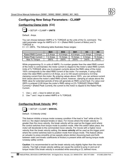
Smart Drive Manual Addendum (S6961, S6962, B8961, B8962, 961, 962)Configuring New Setup Parameters - CLAMPConfiguring Clamp Units [CU]EDIT> SETUP > CLAMP > UNITSDefault: AmpsYou can choose between AMPS or % TORQUE as the units of the CL command. Thevalid parameter range for AMPS is 0 < X < (Rated RMS Current of Motor) and %TORQUE is0 < X < 285%. The following table illustrates these ranges:B23 B32 B41 H3 H4Rated RMS Current 2.5 Amps 4.8 Amps 4.6 Amps 2.5 Amps 5 AmpsRated Peak Current 7.2 Amps 10 Amps 10 Amps 6 Amps 10 AmpsMax % Torque 285% 200% 200% 240% 200%While programming CL in units of AMPS, if a number greater than the rated RMS currentof the motor is commanded, the motor current is clipped to the motor’s rated RMS current.Units of % TORQUE allow you to program currents above the RMS value of the motor.100% corresponds to the rated RMS current of the motor. For example, if using a B32motor the rated RMS current is 4.8 Amps, so a CL100 would command a 4.8 Ampclamping current from the motor. By entering values above 100% you can achieve currentlimit values above the motor’s rated RMS current, however, clamping at values above theRMS value for extended periods of time will generate an RMS current fault. If a value over285% is entered (2.85 times the motor’s RMS rating) or [(% TORQUE)*(Rated RMSCurrent)] > [Rated Peak Current], the current to the motor is clipped to the Rated PeakCurrent.1. Use ← and → keys to select an axis.2. Use ↑ and ↓ keys to select AMPS or % TORQUE.Configuring Break Velocity [BV]EDIT> SETUP > CLAMP > BRKVELDefault: 5 {Velocity Units}This feature inhibits a torque mode runaway condition if the load is “lost” while at the CLlimit (i.e. the object clamped breaks or slips). For moves where the break velocity isgreater than the move velocity, the break velocity will be used as the trigger point wherethe control switches from torque mode to position mode. After this switch takes place, themotor will decelerate to the commanded move velocity. For moves with a higher movevelocity than the break velocity setting, the move velocity will be used as the trigger pointwhere the control switches back to position mode from torque mode. This feature allowsan actuator to press smoothly at low speeds where stiction (bouncing back and forthbetween static and kinetic coefficients of friction) is present while still having torque moderunaway safety control.Caution: It is recommended to set the break velocity only slightly higher than the movevelocity. Too high a break velocity setting can cause the control to jump in and out oftorque mode if the break velocity is exceeded while executing a CL defined move.14INDUSTRIAL DEVICES CORPORATION 64 Digital Drive Novato, CA 94949-5704 800-747-0064415-883-2094 FAX
Smart Drive Manual Addendum (S6961, S6962, B8961, B8962, 961, 962)1. Use ← and → keys to select an axis.2. Use the numeric keys to set the break velocity in VE units.New Inputs & OutputsConfiguring Input Definition [ID]EDIT> SETUP > I/O > INPUTSDefault: UUUUUUUUUUUUUUUUSee Configuring Your Inputs & Outputs (I/O) in your SmartDrive manual for more detailson input definition.1. Use ← and → keys to select an Input. The function of the highlighted input will bedisplayed on the top line.2. Once your cursor is on the desired input, use ↑ ↓ to select F (SET CL FORCE 1) or f(SET CL FORCE 2).New Input Character DescriptionsF,f Set CL Force (F specifies axis 1, f specifies axis 2)In addition to being able to set a clamping current via the CL command, the user can alsoset the clamp current on the fly based on an input. When the SET CL FORCE input isasserted during a CL defined move, the control will maintain the torque the motor isproducing at that instant. For example, if the following move is executing: VE1 CL3 DA3GO (CL units are Amps), and a SET CL FORCE input is activated when the motor currentis at 1.5 amps, the current will be clamped to 1.5 amps. If this input is not triggered, thecontrol will clamp the current to 3 amps. The SET CL FORCE input requires a valid CLmove to be in progress otherwise the input is ignored. The SET CL FORCE input isintended for applications clamping to load cell feedback.I Interrupt (Run 98)When activated, motion on all axes is stopped at the stop-rate (see Edit-Setup-Misc-Stop-Rate). The current program is stopped, and processing continues with the first commandin program 98. If no program is running when the input is activated, program 98 will run.This input is ignored while the keypad is in Edit mode. This is a positive edge sensitiveinput, rather than a level sensitive input. If multiple inputs are configured as Interrupts, onlythe first edge of the first activated input will be seen. If subsequent Interrupt inputs goactive while the first Interrupt input is active, no additional interrupts will be seen.Advanced Interrupt handling can be achieved using the (INT98CTRL) and (ARM INT98)variables. The (INT98CTRL) variable determines whether Interrupts can be disabled ornot. The (ARM INT98) variable allows you to arm and disarm the Interrupt as desired.When the Indexer powers up (INT98CTRL) is initialized to 0. In this mode, every interruptresults in an immediate jump to program 98, even if you just entered program 98. Thismeans that it is possible for the interrupt service routine to be interrupted by anotherinterrupt input. This functionality is backwards compatible with earlier versions of firmwarein IDC SmartDrives. The value of (ARM INT98) is ignored.INDUSTRIAL DEVICES CORPORATION 64 Digital Drive Novato, CA 94949-5704 800-747-0064 415-883-2094 FAX15
- Page 1 and 2: Smart Drive Manual Addendum (S6961,
- Page 3 and 4: Smart Drive Manual Addendum (S6961,
- Page 5 and 6: New Command DescriptionsCommands In
- Page 7 and 8: Smart Drive Manual Addendum (S6961,
- Page 9 and 10: Smart Drive Manual Addendum (S6961,
- Page 11 and 12: Smart Drive Manual Addendum (S6961,
- Page 13 and 14: Smart Drive Manual Addendum (S6961,
- Page 15 and 16: Smart Drive Manual Addendum (S6961,
- Page 17: Smart Drive Manual Addendum (S6961,
- Page 21 and 22: Configuring Output Definition [OD]S
- Page 23 and 24: Smart Drive Manual Addendum (S6961,
- Page 25 and 26: Smart Drive Manual Addendum (S6961,